Introduction to Character Animation phần 7 pptx
Bạn đang xem bản rút gọn của tài liệu. Xem và tải ngay bản đầy đủ của tài liệu tại đây (340.35 KB, 18 trang )
To fix this, with the head bone still selected just paint over the
left-behind vertices. By the way, don't worry about the eyes yet.
We'll fix that momentarily.
Reset the bones ( Ctrl TAB , select armature, a-a-Alt g-Alt r).
Go back to Weight Paint mode of the character mesh.
Select the spine bones and the neck bone, and start weight painting.
My weights looked like this:
Paint over the vertices left behind after the
head was moved.
neck weights.
shoulder.l weights.
spine5 weights.
spine4 weights.
spine3 weights.
spine2 weights.
Parenting the eyes to the head bone
When we moved the head, the eyes were getting left behind. We couldn't weight paint them to the head bone while we
were weight painting the body mesh, because the eyes are separate mesh objects.
It's possible to apply an Armature modifier to the eyes, select the head bone, and weight paint the eyes to the head bone.
However, this isn't the best way to do it.
Here's why: We're going to eventually make the eyes track a target. To do so, they need to swivel around their object
centers. If we weight painted the eyes to the head, when we moved the head it would pull the eye vertices away from the
object center, making the eye tracking all funky.
Instead, we'll parent the entire eye object to the head bone not just its component vertices.
Switch out of Weight Paint mode.
Make sure the armature is in Pose mode.
Select one of the eyes.
With the eye still selected, shift-select the head bone.
Parent the eye to the head bone with Ctrl P>>Bone.
Do the same thing with the other eye:
Select the eye
Shift-select the head bone.
Ctrl P>>Bone to parent to the head bone.
N
ow try moving or rotating the head. The eyes should follow along now.
Testing the rig
All right! Switch out of Weight Paint mode, and select the armature. You
can now pose your character! Try out some test poses and test renders to
p
lay around with your new creation!
Very handy tip: So far, we've been using
R to rotate. Try
hitting
R-R (hit it twice in a row). This enables trackball
rotation, and makes positioning bones much easier than regular
old rotation.
spine1 weights.
Parenting the left eye to the head bone.
It'll probably take some practice to get used to the controls. Try these different methods of moving bones to see how they
react differently:
Turn Auto-IK ON.
Select a bone and move it
Select a bone and rotate it. Notice how Auto-IK only kicks in when you move, but not when you rotate.
Turn Auto-IK OFF
Select a bone and move it
Select a bone and rotate it. Notice they do the same thing, EXCEPT when you try to move the upper arm. Moving
the upper arm detaches it from the shoulder. Well, that's easy to fix: don't move the upper arm, just rotate it!
Summary: By weight painting, we told Blender which vertices
to move when we moved the bones. The character finally
moves! Next, we'll build the lower body armature and do some
more weight painting.
Test render.
You can download the .blend file up to this point: Media:BSoD-ItCA-upper_body_weight_paint.blend.
N
ext: Lower body: armature and weight painting
Previous: Upper body: armature
Back to Index
Retrieved from
" />This page was last modified 11:49, 7 September 2006.
BSoD/Introduction to Character Animation/Lower body
armature
From BlenderWiki
< BSoD | Introduction to Character Animation
Building the lower body armature
We'll add the lower body onto the existing upper body armature. Now that you've had some practice with armatures on the
upper body, we can get into a slightly more complex leg setup. Keep in mind this is a purposefully simple rig, see
BSoD/Introduction_to_Rigging/Leg_Rigs for more advanced rigs with better control.
Select the armature and switch to Edit mode (
TAB ).
Switch the draw type back to Octahedron. This will allow us to
better see which direction the bones are facing.
Double check that X-Axis Mirror is still selected.
Select the root of the spine1 bone.
Armature panel settings.
Select the root of spine1.
Symmetrically extrude the hips using Shift E.
Symmetrically extrude the upper legs with Shift E.
Symmetrically extrude the
hips.
Symmetrically extrude the
upper legs.
Symmetrically extrude the lower legs.
Switch to side view ( NumPad 3).
Extrude a foot bone . . .
. . . and a toe bone.
Symmetrically extrude the
lower legs.
Symmetrically extrude the foot.
Symmetrically extrude the toe.
In Side view, select the tip of the upper leg/bottom of the lower leg and
move it forward a little to give the knee some bend. This will make the IK
setup we're about to make work better - it will be difficult to get it to bend
the knee backwards if it initially has some bend in the right direction.
Select the tip of the lower leg, and extrude it downward. This bone won't
deform the mesh, but it will act as the "handle" for the leg's IK setup. This
will all become more clear later.
The bones are all set up now. It's time to adjust some settings. Remember that settings will not automatically update on the
other side like extruding bones did, so we'll have to make changes to the settings on each side separately.
Give a little bend to the knee.
Extruding the foot controller.
Name the bones. I named them
hip.l
upper_leg.l
lower_leg.l
foot.l
toe.l
leg.l
and
hip.r
upper_leg.r
lower_leg.r
foot.r
toe.r
leg.r
Select toe.l.
In the Armature
Bones panel, first
deselect the Con
button to
disconnect the bone
from its current
parent.
Then make it the
child of leg.l by
selecting "leg.l"
from toe.ls
Armature Bones
panel. If you don't
disconnect it first,
when you make it
the child of leg.l the
toe bone will snap
to the tip of the
leg.l bone. If this
happens, undo with
Bone names, lower body.
Settings for the toe.l bone.
The toe.l bone, parented to leg.l
Ctrl Z and disconnect the toe.l first.
After parenting, notice that there's a dotted line that goes from toe.l to leg.l, indicating that toe.l is parented to leg.l.
Select foot.l and do the same thing:
Disconnect foot.l from its parent by clicking the Con button, then
foot.l a child of leg.l. You can't see the dotted line connecting child
and parent because it's hidden by the bones.
Select leg.l and make it the child of "none", or the blank spot at the
bottom of the "child of" menu. The "Con" button will disappear . . .
if there's no parent, theres nothing for this bone to be connected to.
By making leg.l have no parent, it means that no bone higher up in the
hierarchy will move leg.l. The only way it will move is if we move it
directly. As you'll see, this is useful for keeping the feet on the ground.
Switch to Pose mode (
TAB ).
Select the lower_leg.l bone.
Add an IK Solver to lower_leg.l. To do this, in the Constraints
panel under the Edit buttons click the Add Constraint button and
choose IK Solver. This adds a constraint to the selected bone. Note
that in the Constraints panel, there are now settings for the IK
Solver constraint.
Settings for foot.l.
Make the leg.l bone be parented to none.
Add an IK Solver constraint to the lower_leg.l
bone.
In the Constraints panel, type in "Armature" in the OB: text box.
Type in "foot.l" in the BO: text box. We just told the constraint that
the target will be the foot.l bone in the armature object called
Armature.
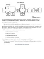
A constraint is a way of sort of programming how a bone should act. For example, one type of constraint on that menu is a
Track To constraint. You tell the constraint what object you want the bone to track, and then whenever you move that
object, the bone will point to it.
Well, the IK Solver constraint is similar. We'll tell the constraint what it's Target should be, and it will try to point the
bone and its whole chain at that target by solving lots of equations. You'll have to wait and see till it's set up to see the
advantage over Auto-IK . . .
Important: Make sure Auto IK is OFF in the Armature panel.
Try moving leg.l, the controller for the leg. The whole armature
moves along, spine and everything attached to it. That's not right!
Remember we had a similar problem with the arms, and fixed it by
disconnecting the shoulder in order to break the chain. This time,
though, there's a setting in the IK Solver constraint made for fixing
just this sort of thing.
Select the lower_leg.l bone again.
In the Constraint panel under the IK Solver constraint, change
ChainLen to 2. By default, ChainLen is zero, (or undefined)
meaning that the IK Solver involves the entire chain no matter how
long it is. By changing it to 2, we told the IK Solver that the chain
is only 2 bones long - in other words, only the lower_leg.l bone and
the upper_leg.l bone.
The lower_leg.l IK Solver constraint.
IK Solver doesn't work right with the default
settings . . .
Changing ChainLen to 2.
Try selecting the leg.l bone again and moving it. Just the leg should
move now.
N
ow do the same thing to the right side of the body:
In Edit mode, disconnect toe.r and make it the child of leg.r.
Disconnect foot.r and make it the child of leg.r.
Make leg.r the child of none.
Switch to Pose mode.
Add an IK Solver constraint to lower_leg.r. Make the target foot.r
in the object Armature. Alternative: a faster way to add an IK
constraint is by selecting the Target (foot.r), then shift-selecting the
bone (lower_leg.r) and pressing
Ctrl i.
Change the ChainLen to 2.
Weight paint the lower body
From working on the upper body, you know how to weight paint. Let's do
the same thing for the lower body.
In Pose mode, clear the location and rotation of all bones with
A-A-Alt R-Alt G.
In the Armature panel, change the draw type back to Stick.
Select the character mesh.
Ctrl TAB to get into Weight Paint mode.
Double check:
X-Mirror is selected (important!)
All Faces and Vertex Dist are unselected
Weight is set to 1.0
Opacity is set to 1.0
Select each bone and start weight painting, remember to rotate the view around to paint all vertices. I ended up not
using the hip bones directly - the character was deforming fine without them, so there are no weights shown here.
Now moving leg.l works correctly.
upper_leg.l weights.
lower_leg.l weights.
Test poses
Try out the new functionality with some test poses, and render with F12 .
Summary: We constructed the lower body armature, added IK
constraints, and weight painted it. Next we'll tweak the rig to
make it easier to control.
N
ext: Final rig adjustments
Previous: Upper body: weight painting
Back to Index
Retrieved from
" />This page was last modified 21:55, 15 September 2006.
foot.l weights.
toe.l weights.
Test pose
BSoD/Introduction to Character Animation/Final rig
adjustments
From BlenderWiki
< BSoD | Introduction to Character Animation
Contents
1 Final adjustments
2 Adding a master bone
3 Eye tracking
4 Tips for using the rig
Final adjustments
In this section, we'll make some final adjustments to the rig to make it easier to control. Specifically, we'll add:
a master bone so we can move the entire character at once.
knee-lock targets so we can control where the knees point.
an eye target bone so we can easily change which direction the eyes are looking.
Adding a master bone
Select the armature and enter Edit mode.
Select the tip of spine1 and extrude it backward with E.
In the Armature Bones panel of the Edit buttons, name this bone
something meaningful. I named it "master".
Make this new bone the child of none, so that the only way this
bone will move is if we move it directly.
This bone will the be highest parent of all the other bones in the armature. The master bone will be the one to move when
we want to move the whole body at once, like in a jump.
For each bone (spine1, leg.l, and leg.r)
Select the bone.
Choose master in the Child of menu to parent it to the master bone.
N
ote that dotted lines are now drawn from each bone to the master bone. Now when we move master in Pose mode, the
entire armature and body will move.
Extruded master bone.
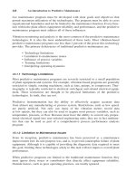
Here's something that needs fixing: in Pose mode, grab the spine1
bone and move it around. When you move it forward and down, you
get something like this.
But when you move it back and down, you get something like this.
Ouch!
The IK constraints on the legs are doing their job. They're trying to keep the leg pointed at the leg target, and they don't
know that knees only bend one way. To fix this, we'll add another constraint to the upper leg bone to keep it pointing in
the direction we tell it.
Moving spine1 down and forward: works
OK.
The IK constraints don't work well in this
direction.
Clear location and rotation of all bones ( A-A-Alt G-Alt R).
Switch to the armature's Edit mode.
Select the tip of the upper leg bone (at the knee) and symmetrically
extrude a bone forward.
For each of the two new bones (remember you have to change these
settings individually, they're not automatically symmetrical):
Name the bone (I called them knee.l and knee.r).
Disconnect the bone (Click the Con button).
Make it the child of master.
In Side view, move the knee bones away from the actual knees.
These bones will be acting as targets for the upper legs, and if
they're too close the upper legs might not know what to point to. I
also scaled them down a little with
S so they're less in the way.
Remember, with X-Axis Mirror selected, you only have to move
and scale one bone, and the other will automatically update.
Extruded knee bones (view rotated for clarity).
Settings for the knee.l bone.
Knee bones moved away from the mesh.
N
ow we'll add another IK Constraint to the upper legs, telling them to try
to point to the new knee bones.
Switch to Pose mode.
First select knee.l, then shift-select upper_leg.l.
Add an IK constraint with Ctrl I . Whoa, the armature goes
crazy! That's because by default, the ChainLen is 0, which means
the IK constraint tries to point as long of a chain as it can toward
the knee bone. That chain includes hip.l and spine1, so it tries to
point them to the knee.l target as well.
We only want a single bone chain (just uper_leg.l) to point to the
knee, so change the ChainLen of the IK constraint on upper_leg.l to
1.
Armature directly after adding an IK constraint
to upper_leg.l.
Change the ChainLen to 1 to fix the armature.