rfid handbook fundamentals and applications in contactless smart cards and identification second edition phần 1 ppt
Bạn đang xem bản rút gọn của tài liệu. Xem và tải ngay bản đầy đủ của tài liệu tại đây (1.93 MB, 52 trang )
.
.RFID Handbook: Fundamentals and Applications in
Contactless Smart Cards and Identification, Second Edition
by Klaus Finkenzeller
ISBN:0470844027
John Wiley & Sons © 2003
This volume provides an overview suited for users of radio
frequency identification (RFID) products and electrical
engineering students, covering industry standards and
regulations, algorithms, applications, and more.
Table of Contents
RFID Handbook?Fundamentals and Applications in Contactless Smart Cards and
Identification, Second Edition
Preface to the 2nd Edition
List of Abbreviations
Chapter 1-Introduction
Chapter 2-Differentiation Features of RFID Systems
Chapter 3-Fundamental Operating Principles
Chapter 4-Physical Principles of RFID Systems
Chapter 5-Frequency Ranges and Radio Licensing Regulations
Chapter 6-Coding and Modulation
Chapter 7-Data Integrity
Chapter 8-Data Security
Chapter 9-Standardisation
Chapter 10-The Architecture of Electronic Data Carriers
Chapter 11-Readers
Chapter 12-The Manufacture of Transponders and Contactless Smart Cards
Chapter 13-Example Applications
Chapter 14-Appendix
Index
List of Figures
List of Tables
This document was created by an unregistered ChmMagic, please go to to register it. Thanks.
Back Cover
Developments in RFID (Radio-Frequency Identification) are yielding larger memory
capacities, wider reading ranges and quicker processing, making it one of the fastest
growing sectors of the radio technology industry.
RFID has become indispensable in a wide range automated data capture and
identification applications, from ticketing and access control to industrial automation.
The second edition of Finkezeller’s comprehensive handbook brings together the
disparate information on this versatile technology. Features include:
Essential new information on the industry standards and regulations,
including ISO 14443 (contactless ticketing), ISO 15693 (smartlabel)
and ISO 14223 (animal identification).
Complete coverage of the physical principles behind RFID
technologies such as inductive coupling, surface acoustic waves and
the emerging UHF and microwave backscatter systems.
A detailed description of common algorithms for anticollision.
An exhaustive appendix providing listings of FRID association,
journals, and standards.
A sample test card layout in accordance with ISO 14443.
Numerous sample applications including e-ticketing in public transport
systems and animal identification.
End users of RFID products, electrical engineering students and newcomers to the
field will value this introduction to the functionality of RFID technology and the physical
principles involved. Experienced ADC professionals will benefit from the breadth of
applications examples combined within this single resource.
This document was created by an unregistered ChmMagic, please go to to register it. Thanks.
RFID Handbook—Fundamentals and
Applications in Contactless Smart Cards and
Identification, Second Edition
Klaus Finkenzeller Giesecke & Devrient GmbH,
Munich Germany
Translated by Rachel Waddington Member of the Institute of Translation and
Interpreting
First published under the title RFID-Handbuch, 2 Auflage by Carl Hanser
Verlag
© Carl Hanser Verlag, Munich/FRG, 1999 All rights reserved
Authorized translation from the 2nd edition in the original German language
published by Carl Hanser Verlag, Munich/FRG
Copyright © 2003 John Wiley & Sons Ltd, The Atrium, Southern Gate,
Chichester, West Sussex PO19 8SQ, England
Telephone (+44) 1243 779777
Email (for orders and customer service enquiries): <>
Visit our Home Page on www.wileyeurope.com or www.wiley.com
Reprinted September 2003
All Rights Reserved. No part of this publication may be reproduced, stored in a
retrieval system or transmitted in any form or by any means, electronic,
mechanical, photocopying, recording, scanning or otherwise, except under the
terms of the Copyright, Designs and Patents Act 1988 or under the terms of a
licence issued by the Copyright Licensing Agency Ltd, 90 Tottenham Court
Road, London W1T 4LP, UK, without the permission in writing of the Publisher.
Requests to the Publisher should be addressed to the Permissions
Department, John Wiley & Sons Ltd, The Atrium, Southern Gate, Chichester,
West Sussex PO19 8SQ, England, or emailed to <>, or
faxed to (+44) 1243 770620.
This publication is designed to provide accurate and authoritative information in
regard to the subject matter covered. It is sold on the understanding that the
Publisher is not engaged in rendering professional services. If professional
advice or other expert assistance is required, the services of a competent
professional should be sought.
Other Wiley Editorial Offices
John Wiley & Sons Inc., 111 River Street, Hoboken, NJ 07030, USA
Jossey-Bass, 989 Market Street, San Francisco, CA 94103-1741, USA
This document was created by an unregistered ChmMagic, please go to to register it. Thanks.
Wiley-VCH Verlag GmbH, Boschstr. 12, D-69469 Weinheim, Germany
John Wiley & Sons Australia Ltd, 33 Park Road, Milton, Queensland 4064,
Australia
John Wiley & Sons (Asia) Pte Ltd, 2 Clementi Loop #02-01, Jin Xing Distripark,
Singapore 129809
John Wiley & Sons Canada Ltd, 22 Worcester Road, Etobicoke, Ontario,
Canada M9W 1L1
Wiley also publishes its books in a variety of electronic formats. Some content
that appears in print may not be available in electronic books.
Library of Congress Cataloging-in-Publication Data
Finkenzeller, Klaus.
[RFID Handbuch. English]
RFID handbook : fundamentals and applications in contactless smart cards and
identifcation/Klaus Finkenzeller; translated by Rachel Waddington. — 2nd ed.
p. cm.
Includes bibliographical references and index.
ISBN 0-470-84402-7 (alk. paper)
1. Inventory control — Automation. 2. Radio frequency identification systems.
3. Smart. cards. I. Title.
TS160.F5513 2003
658.7'87 — dc21
2002192439
British Library Cataloguing in Publication Data
A catalogue record for this book is available from the British Library
ISBN 0-470-84402-7
Typeset in 10/12pt Times by
Laserwords Private Limited, Chennai, India
Printed and bound in Great Britain by
Antony Rowe Ltd, Chippenham, Wiltshire
This book is printed on acid-free paper responsibly manufactured from
sustainable forestry in which at least two trees are planted for each one used
for paper production.
This document was created by an unregistered ChmMagic, please go to to register it. Thanks.
Preface to the 2nd Edition
This book is aimed at an extremely wide range of readers. First and foremost it
is intended for students and engineers who find themselves confronted with
RFID technology for the first time. A few basic chapters are provided for this
audience describing the functionality of RFID technology and the physical and
IT-related principles underlying this field. The book is also intended for
practitioners who, as users, wish to or need to obtain as comprehensive and
detailed an overview of the various technologies, the legal framework or the
possible applications of RFID as possible.
Although a wide range of individual articles are now available on this subject,
the task of gathering all this scattered information together when it is needed is
a tiresome and time-consuming one — as researching this book has proved.
This book therefore aims to fill a gap in the range of literature on the subject of
RFID. The need for well-founded technical literature in this field is proven by
the fortunate fact that this book has now also appeared in Chinese and
Japanese translation. Further information on the German version of the RFID
handbook and the translations can be found on the homepage of this book,
.
This book uses numerous pictures and diagrams to attempt to give a graphic
representation of RFID technology in the truest sense of the word. Particular
emphasis is placed on the physical principles of RFID, which is why the
chapter on this subject is by far the most comprehensive of the book. However,
practical considerations are also assigned great importance. For this reason
the chapter entitled 'Example Applications' is also particularly comprehensive.
Technological developments in the field of RFID technology are proceeding at
such a pace that although a book like this can explain the general scientific
principles it is not dynamic enough to be able to explore the latest trends
regarding the most recent products on the market and the latest standards and
regulations. I am therefore grateful for any suggestions and advice —
particularly from the field of industry. The basic concepts and underlying
physical principles remain, however, and provide a good background for
understanding the latest developments.
Unfortunately, the market overview that was previously included has had to be
omitted from the 2nd edition of the book, as the growing number of providers
has made it increasingly difficult to retain an overview of the numerous
transponders available on the market. However, a detailed introduction to the
physical principles of UHF and microwave systems (Section 4.2), which will
become increasingly important in Europe with the approval of the
corresponding frequency ranges in the 868 MHz band, has been added. The
chapter on standardisation has been extended in order to keep up with the
rapid development in this field.
At this point I would also like to express my thanks to those companies which
were kind enough to contribute to the success of this project by providing
numerous technical data sheets, lecture manuscripts, drawings and
photographs.
This document was created by an unregistered ChmMagic, please go to to register it. Thanks.
Klaus Finkenzeller
Munich, Summer 2002
This document was created by an unregistered ChmMagic, please go to to register it. Thanks.
List of Abbreviations
µP
Microprocessor
µs
Microsecond (10
-6
seconds)
ABSAcrylnitrilbutadienstyrol
ACMAccess Configuration Matrix
AFCAutomatic Fare Collection
AFIApplication Family Identifier (see ISO 14443-3)
AIApplication Identifier
AMAmplitude Modulation
APDUApplication Data Unit
ASICApplication Specific Integrated Circuit
ASCIIAmerican Standard Code for Information Interchange
ASKAmplitude Shift Keying
ATQAnswer to Request (ATQA, ATQB: see ISO 14443-3)
ATRAnswer to Reset
AVIAutomatic Vehicle Identification (for Railways)
BAPTBundesamt für Post und Telekommunikation
BdBaud, transmission speed in bit/s
BGTBlock Guard Time
BMBFBundesministerium für Bildung und Forschung
(Ministry for Education and Research, was BMFT)
BPBandpass filter
CCapacitance (of a capacitor)
CCGCentrale für Coorganisation GmbH (central
allocation point for EAN codes in Germany)
CENComité Européen de Normalisation
CEPTConférence Européene des Postes et
Télécommunications
CICCClose Coupling Integrated Circuit Chip Card
CIUContactless Interface Unit (transmission/receiving
module for contactless microprocessor interfaces)
CLKClock (timing signal)
CRCCyclic Redundancy Checksum
CCITTComité Consultatif International Télégraphique et
Téléphonique
This document was created by an unregistered ChmMagic, please go to to register it. Thanks.
dBmLogarithmic measure of power, related to 1 mW
HF-power (0 dBm = 1 mW, 30 dBm = 1W)
DBPDifferential Bi-Phase encoding
DINDeutsche Industrienorm (German industrial
standard)
EANEuropean Article Number (barcode on groceries and
goods)
EASElectronic Article Surveillance
ECEurocheque or electronic cash
ECCEuropean Communications Committee
EDIElectronic Document Interchange
EEPROMElectric Erasable and Programmable Read-Only
Memory
EMCElectromagnetic Compatibility
EOFEnd of Frame
ERCEuropean Radiocommunications Committee
ERMElectromagnetic Compatibility and Radio Spectrum
Matters
EROEuropean Radiocommunications Organisation
EROEuropean Radio Office
ERPEquivalent Radiated Power
ETCSEuropean Train Control System
ETSEuropean Telecommunication Standard
ETSIEuropean Telecommunication Standards Institute
EVCEuropean Vital Computer (part of ETCS)
FCCFederal Commission of Communication
FDXFull-Duplex
FHSSFrequency Hopping Spread Spectrum
FMFrequency modulation
FRAMFerroelectric Random Access Memory
FSKFrequency Shift Keying
GSMGlobal System for Mobile Communication (was
Groupe Spécial Mobile)
GTAGGlobal-Tag (RFID Initiative of EAN and the UCC)
HDXHalf-Duplex
HFHigh Frequency (3 30 MHz)
I
2
C
Inter-IC-Bus
ICCIntegrated Chip Card
This document was created by an unregistered ChmMagic, please go to to register it. Thanks.
IDIdentification
ISMIndustrial Scientific Medical (frequency range)
ISOInternational Organization for Standardization
LLoop (inductance of a coil)
LANLocal Area Network
LFLow Frequency (30 300 kHz)
LPDLow Power Device (low power radio system for the
transmission of data or speech over a few hundred
metres)
LRCLongitudinal Redundancy Check
LSBLeast Significant Bit
MADMIFARE® Application Directory
MSBMost Significant Bit
NADNode Address
nomLNon-public mobile land radio (industrial radio,
transport companies, taxi radio, etc.)
NRZNon-Return-to-Zero Encoding
NTCNegative Temperature Coefficient (thermal resistor)
NVBNumber of Valid Bits (see ISO 14443-3)
OCROptical Character Recognition
OEMOriginal Equipment Manufacturer
OTPOne Time Programmable
PCPersonal Computer
PCDProximity Card Device (see ISO 14443)
PICCProximity Integrated Contactless Chip Card (see
ISO 14443)
PKIPublic Key Infrastructure
PMUPower Management Unit
PPPlastic Package
PPSPolyphenylensulfide
PSKPhase Shift Keying
PUPIPseudo Unique PICC Identifier (see ISO 14443-3)
PVCPolyvinylchloride
R&TTERadio and Telecommunication Terminal Equipment
(The Radio Equipment and Telecommunications
Terminal Equipment Directive (1999/5/EC))
RADARRadio Detecting and Ranging
RAMRandom Access Memory
RCSRadar Cross-Section
This document was created by an unregistered ChmMagic, please go to to register it. Thanks.
REQRequest
RFIDRadio Frequency Identification
RFUReserved for Future Use
RTIReturnable Trade Items
RTIRoad Transport Information System
RTTTRoad Transport & Traffic Telematics
RWDRead Write Device
SAMSecurity Authentication Module
SAWSurface Acoustic Wave
SCL
Serial Clock (I
2
C Bus Interface)
SDA
Serial Data Address Input Output (I
2
C Bus Interface)
SEQSequential System
SMDSurface Mounted Devices
SNRSerial Number
SOFStart of Frame
SRAMStatic Random Access Memory
SRDShort Range Devices (low power radio systems for
the transmission of data or voice over short
distances, typically a few hundred metres)
TRTechnische Richtlinie (Technical Guideline)
UARTUniversal Asynchronous Receiver Transmitter
(transmission/receiving module for computer
interfaces)
UCCUniversal Code Council (American standard for
barcodes on groceries and goods)
UHFUltra High Frequency (300 MHz 3 GHz)
UPCUniversal Product Code
VCDVicinity Card Device (see ISO 15693)
VDEVerein Deutscher Elektrotechniker (German
Association of Electrical Engineers)
VICCVicinity Integrated Contactless Chip Card (see ISO
15693)
VSWRVoltage Standing Wave Ratio
XOReXclusive-OR
ZVZulassungsvorschrift (Licensing Regulation)
HITAG® and
MIFARE®
are registered trademarks of Philips elektronics N.V.
LEGIC®is a registered trademark of Kaba Security Locking
Systems AG
This document was created by an unregistered ChmMagic, please go to to register it. Thanks.
MICROLOG®is a registered trademark of Idesco
TIRIS®is a registered trademark of Texas Instruments
TROVAN®is a registered trademark of AEG ID systems
This document was created by an unregistered ChmMagic, please go to to register it. Thanks.
Chapter 1: Introduction
Overview
In recent years automatic identification procedures (Auto-ID) have become very
popular in many service industries, purchasing and distribution logistics, industry,
manufacturing companies and material flow systems. Automatic identification
procedures exist to provide information about people, animals, goods and products in
transit.
The omnipresent barcode labels that triggered a revolution in identification systems
some considerable time ago, are being found to be inadequate in an increasing
number of cases. Barcodes may be extremely cheap, but their stumbling block is their
low storage capacity and the fact that they cannot be reprogrammed.
The technically optimal solution would be the storage of data in a silicon chip. The
most common form of electronic data-carrying device in use in everyday life is the
smart card based upon a contact field (telephone smart card, bank cards). However,
the mechanical contact used in the smart card is often impractical. A contactless
transfer of data between the data-carrying device and its reader is far more flexible. In
the ideal case, the power required to operate the electronic data-carrying device
would also be transferred from the reader using contactless technology. Because of
the procedures used for the transfer of power and data, contactless ID systems are
called RFID systems (Radio Frequency Identification).
The number of companies actively involved in the development and sale of RFID
systems indicates that this is a market that should be taken seriously. Whereas global
sales of RFID systems were approximately 900 million $US in the year 2000 it is
estimated that this figure will reach 2650 million $US in 2005 (Krebs, n.d.). The RFID
market therefore belongs to the fastest growing sector of the radio technology
industry, including mobile phones and cordless telephones, (Figure 1.1).
Figure 1.1: The estimated growth of the global market for RFID systems
between 2000 and 2005 in million $US, classified by application
Furthermore, in recent years contactless identification has been developing into an
independent interdisciplinary field, which no longer fits into any of the conventional
pigeon holes. It brings together elements from extremely varied fields: HF technology
This document was created by an unregistered ChmMagic, please go to to register it. Thanks.
and EMC, semiconductor technology, data protection and cryptography,
telecommunications, manufacturing technology and many related areas.
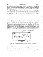
As an introduction, the following section gives a brief overview of different automatic
ID systems that perform similar functions to RFID (Figure 1.2).
Figure 1.2: Overview of the most important auto-ID procedures
This document was created by an unregistered ChmMagic, please go to to register it. Thanks.
1.1 Automatic Identification Systems
1.1.1 Barcode systems
Barcodes have successfully held their own against other identification systems over
the past 20 years. According to experts, the turnover volume for barcode systems
totalled around 3 billion DM in Western Europe at the beginning of the 1990s (Virnich
and Posten, 1992).
The barcode is a binary code comprising a field of bars and gaps arranged in a
parallel configuration. They are arranged according to a predetermined pattern and
represent data elements that refer to an associated symbol. The sequence, made up
of wide and narrow bars and gaps, can be interpreted numerically and
alphanumerically. It is read by optical laser scanning, i.e. by the different reflection of a
laser beam from the black bars and white gaps (ident, 1996). However, despite being
identical in their physical design, there are considerable differences between the code
layouts in the approximately ten different barcode types currently in use.
The most popular barcode by some margin is the EAN code (European Article
Number), which was designed specifically to fulfil the requirements of the grocery
industry in 1976. The EAN code represents a development of the UPC (Universal
Product Code) from the USA, which was introduced in the USA as early as 1973.
Today, the UPC represents a subset of the EAN code, and is therefore compatible
with it (Virnich and Posten, 1992).
The EAN code is made up of 13 digits: the country identifier, the company identifier,
the manufacturer's item number and a check digit (Figure 1.3).
Figure 1.3: Example of the structure of a barcode in EAN coding
In addition to the EAN code, the following barcodes are popular in other industrial
fields (see Figure 1.4):
Code Codabar: medical/clinical applications, fields with high safety
requirements.
Code 2/5 interleaved: automotive industry, goods storage, pallets,
shipping containers and heavy industry.
Code 39: processing industry, logistics, universities and libraries.
This document was created by an unregistered ChmMagic, please go to to register it. Thanks.
Figure 1.4: This barcode is printed on the back of this book and contains the
ISBN number of the book
1.1.2 Optical character recognition
Optical character recognition (OCR) was first used in the 1960s. Special fonts were
developed for this application that stylised characters so that they could be read both
in the normal way by people and automatically by machines. The most important
advantage of OCR systems is the high density of information and the possibility of
reading data visually in an emergency (or simply for checking) (Virnich and Posten,
1992).
Today, OCR is used in production, service and administrative fields, and also in banks
for the registration of cheques (personal data, such as name and account number, is
printed on the bottom line of a cheque in OCR type).
However, OCR systems have failed to become universally applicable because of their
high price and the complicated readers that they require in comparison with other ID
procedures.
1.1.3 Biometric procedures
Biometrics is defined as the science of counting and (body) measurement procedures
involving living beings. In the context of identification systems, biometry is the general
term for all procedures that identify people by comparing unmistakable and individual
physical characteristics. In practice, these are fingerprinting and handprinting
procedures, voice identification and, less commonly, retina (or iris) identification.
1.1.3.1 Voice identification
Recently, specialised systems have become available to identify individuals using
speaker verification (speaker recognition). In such systems, the user talks into a
microphone linked to a computer. This equipment converts the spoken words into
digital signals, which are evaluated by the identification software.
The objective of speaker verification is to check the supposed identity of the person
based upon their voice. This is achieved by checking the speech characteristics of the
speaker against an existing reference pattern. If they correspond, then a reaction can
be initiated (e.g. 'open door').
1.1.3.2 Fingerprinting procedures (dactyloscopy)
Criminology has been using fingerprinting procedures for the identification of criminals
since the early twentieth century. This process is based upon the comparison of
papillae and dermal ridges of the fingertips, which can be obtained not only from the
finger itself, but also from objects that the individual in question has touched.
When fingerprinting procedures are used for personal identification, usually for
entrance procedures, the fingertip is placed upon a special reader. The system
calculates a data record from the pattern it has read and compares this with a stored
reference pattern. Modern fingerprint ID systems require less than half a second to
This document was created by an unregistered ChmMagic, please go to to register it. Thanks.
recognise and check a fingerprint. In order to prevent violent frauds, fingerprint ID
systems have even been developed that can detect whether the finger placed on the
reader is that of a living person (Schmidhäusler, 1995).
1.1.4 Smart cards
A smart card is an electronic data storage system, possibly with additional computing
capacity (microprocessor card), which — for convenience — is incorporated into a
plastic card the size of a credit card. The first smart cards in the form of prepaid
telephone smart cards were launched in 1984. Smart cards are placed in a reader,
which makes a galvanic connection to the contact surfaces of the smart card using
contact springs. The smart card is supplied with energy and a clock pulse from the
reader via the contact surfaces. Data transfer between the reader and the card takes
place using a bidirectional serial interface (I/O port). It is possible to differentiate
between two basic types of smart card based upon their internal functionality: the
memory card and the microprocessor card.
One of the primary advantages of the smart card is the fact that the data stored on it
can be protected against undesired (read) access and manipulation. Smart cards
make all services that relate to information or financial transactions simpler, safer and
cheaper. For this reason, 200 million smart cards were issued worldwide in 1992. In
1995 this figure had risen to 600 million, of which 500 million were memory cards and
100 million were microprocessor cards. The smart card market therefore represents
one of the fastest growing subsectors of the microelectronics industry.
One disadvantage of contact-based smart cards is the vulnerability of the contacts to
wear, corrosion and dirt. Readers that are used frequently are expensive to maintain
due to their tendency to malfunction. In addition, readers that are accessible to the
public (telephone boxes) cannot be protected against vandalism.
1.1.4.1 Memory cards
In memory cards the memory — usually an EEPROM — is accessed using a
sequential logic (state machine) (Figure 1.5). It is also possible to incorporate simple
security algorithms, e.g. stream ciphering, using this system. The functionality of the
memory card in question is usually optimised for a specific application. Flexibility of
application is highly limited but, on the positive side, memory cards are very cost
effective. For this reason, memory cards are predominantly used in price sensitive,
large-scale applications (Rankl and Effing, 1996). One example of this is the national
insurance card used by the state pension system in Germany (Lemme, 1993).
Figure 1.5: Typical architecture of a memory card with security logic
1.1.4.2 Microprocessor cards
As the name suggests, microprocessor cards contain a microprocessor, which is
connected to a segmented memory (ROM, RAM and EEPROM segments).
This document was created by an unregistered ChmMagic, please go to to register it. Thanks.
The mask programmed ROM incorporates an operating system (higher programme
code) for the microprocessor and is inserted during chip manufacture. The contents of
the ROM are determined during manufacturing, are identical for all microchips from
the same production batch, and cannot be overwritten.
The chip's EEPROM contains application data and application-related programme
code. Reading from or writing to this memory area is controlled by the operating
system.
The RAM is the microprocessor's temporary working memory. Data stored in the RAM
are lost when the supply voltage is disconnected (Figure 1.6).
Figure 1.6: Typical architecture of a microprocessor card
Microprocessor cards are very flexible. In modern smart card systems it is also
possible to integrate different applications in a single card (multi-application). The
application-specific parts of the programme are not loaded into the EEPROM until
after manufacture and can be initiated via the operating system.
Microprocessor cards are primarily used in security sensitive applications. Examples
are smart cards for GSM mobile phones and the new EC (electronic cash) cards. The
option of programming the microprocessor cards also facilitates rapid adaptation to
new applications (Rankl and Effing, 1996).
1.1.5 RFID systems
RFID systems are closely related to the smart cards described above. Like smart card
systems, data is stored on an electronic data-carrying device — the transponder.
However, unlike the smart card, the power supply to the data-carrying device and the
data exchange between the data-carrying device and the reader are achieved without
the use of galvanic contacts, using instead magnetic or electromagnetic fields. The
underlying technical procedure is drawn from the fields of radio and radar
engineering. The abbreviation RFID stands for radio frequency identification, i.e.
information carried by radio waves. Due to the numerous advantages of RFID
systems compared with other identification systems, RFID systems are now
beginning to conquer new mass markets. One example is the use of contactless
smart cards as tickets for short-distance public transport.
This document was created by an unregistered ChmMagic, please go to to register it. Thanks.
1.2 A Comparison of Different ID Systems
A comparison between the identification systems described above highlights the
strengths and weakness of RFID in relation to other systems (Table 1.1). Here too,
there is a close relationship between contact-based smart cards and RFID systems;
however, the latter circumvents all the disadvantages related to faulty contacting
(sabotage, dirt, unidirectional insertion, time consuming insertion, etc.).
This document was created by an unregistered ChmMagic, please go to to register it. Thanks.
Table 1.1: Comparison of different RFID systems showing their advantages and disadvantages
System parametersBarcodeOCRVoice
recog.
BiometrySmart card
Typical data
quantity (bytes)
1–1001–100——16–64 k
Data densityLowLowHighHighVery high
Machine readabilityGoodGoodExpensiveExpensiveGood
Readability by
people
LimitedSimpleSimpleDifficultImpossible
Influence of
dirt/damp
Very
high
Very
high
——Possible
(contacts)
Influence of (opt.)
covering
Total
failure
Total
failure
—Possible—
Influence of
direction and
position
LowLow——Unidirectional
Degradation/wearLimitedLimited——Contacts
Purchase
cost/reading
electronics
Very lowMediumVery highVery highLow
Operating costs
(e.g. printer)
LowLowNoneNoneMedium
(contacts)
Unauthorised
copying/modification
SlightSlight
Possible
[*]
(audio
tape)
ImpossibleImpossible
Reading speed
(including handling
of data carrier)
Low
~4s
Low
~3s
Very low
>5s
Very low
>5-10s
Low
~4s
Maximum distance
between data
carrier and reader
0–50 cm<1 cm
Scanner
0–50 cmDirect
contact
[**]
Direct
contact
[*]
The danger of 'Replay' can be reduced by selecting the text to be spoken using a random generator, because
the text that must be spoken is not known in advance.
[**]
This only applies for fingerprint ID. In the case of retina or iris evaluation direct contact is not necessary or
possible.
This document was created by an unregistered ChmMagic, please go to to register it. Thanks.
1.3 Components of an RFID System
An RFID system is always made up of two components (Figure 1.7):
the transponder, which is located on the object to be identified;
the interrogator or reader, which, depending upon the design and
the technology used, may be a read or write/read device (in this
book — in accordance with normal colloquial usage — the data
capture device is always referred to as the reader, regardless of
whether it can only read data or is also capable of writing).
Figure 1.7: The reader and transponder are the main components of every
RFID system
A practical example is shown in Figure 1.8.
Figure 1.8: RFID reader and contactless smart card in practical use
(reproduced by permission of Kaba Benzing GmbH)
A reader typically contains a radio frequency module (transmitter and receiver), a
control unit and a coupling element to the transponder. In addition, many readers are
fitted with an additional interface (RS 232, RS 485, etc.) to enable them to forward the
data received to another system (PC, robot control system, etc.).
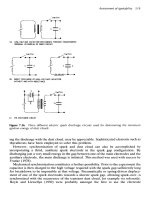
The transponder, which represents the actual data-carrying device of an RFID system,
normally consists of a coupling element and an electronic microchip (Figure 1.9).
When the transponder, which does not usually possess its own voltage supply
(battery), is not within the interrogation zone of a reader it is totally passive. The
transponder is only activated when it is within the interrogation zone of a reader. The
power required to activate the transponder is supplied to the transponder through the
coupling unit (contactless), as are the timing pulse and data.
This document was created by an unregistered ChmMagic, please go to to register it. Thanks.
Figure 1.9: Basic layout of the RFID data-carrying device, the transponder.
Left, inductively coupled transponder with antenna coil; right, microwave
transponder with dipolar antenna
This document was created by an unregistered ChmMagic, please go to to register it. Thanks.
Chapter 2: Differentiation Features of RFID
Systems
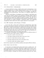
2.1 Fundamental Differentiation Features
RFID systems exist in countless variants, produced by an almost equally high
number of manufacturers. If we are to maintain an overview of RFID systems
we must seek out features that can be used to differentiate one RFID system
from another (Figure 2.1).
Figure 2.1: The various features of RFID systems (Integrated Silicon
Design, 1996)
RFID systems operate according to one of two basic procedures: full duplex
(FDX)/ half duplex (HDX) systems, and sequential systems (SEQ).
In full and half duplex systems the transponder's response is broadcast when
the reader's RF field is switched on. Because the transponder's signal to the
receiver antenna can be extremely weak in comparison with the signal from the
reader itself, appropriate transmission procedures must be employed to
differentiate the transponder's signal from that of the reader. In practice, data
transfer from transponder to reader takes place using load modulation, load
modulation using a subcarrier, but also (sub)harmonics of the reader's
transmission frequency.
This document was created by an unregistered ChmMagic, please go to to register it. Thanks.
In contrast, sequential procedures employ a system whereby the field from the
reader is switched off briefly at regular intervals. These gaps are recognised by
the transponder and used for sending data from the transponder to the reader.
The disadvantage of the sequential procedure is the loss of power to the
transponder during the break in transmission, which must be smoothed out by
the provision of sufficient auxiliary capacitors or batteries.
The data capacities of RFID transponders normally range from a few bytes to
several kilobytes. So-called 1-bit transponders represent the exception to this
rule. A data quantity of exactly 1-bit is just enough to signal two states to the
reader: 'transponder in the field' or 'no transponder in the field'. However, this is
perfectly adequate to fulfil simple monitoring or signalling functions. Because a
1-bit transponder does not need an electronic chip, these transponders can be
manufactured for a fraction of a penny. For this reason, vast numbers of 1-bit
transponders are used in Electronic Article Surveillance (EAS) to protect goods
in shops and businesses. If someone attempts to leave the shop with goods
that have not been paid for the reader installed in the exit recognises the state
'transponder in the field' and initiates the appropriate reaction. The 1-bit
transponder is removed or deactivated at the till when the goods are paid for.
The possibility of writing data to the transponder provides us with another way
of classifying RFID systems. In very simple systems the transponder's data
record, usually a simple (serial) number, is incorporated when the chip is
manufactured and cannot be altered thereafter. In writable transponders, on
the other hand, the reader can write data to the transponder. Three main
procedures are used to store the data: in inductively coupled RFID systems
EEPROMs (electrically erasable programmable read-only memory) are
dominant. However, these have the disadvantages of high power consumption
during the writing operation and a limited number of write cycles (typically of
the order of 100 000 to 1 000 000). FRAMs (ferromagnetic random access
memory) have recently been used in isolated cases. The read power
consumption of FRAMs is lower than that of EEPROMs by a factor of 100 and
the writing time is 1000 times lower. Manufacturing problems have hindered its
widespread introduction onto the market as yet.
Particularly common in microwave systems, SRAMs (static random access
memory) are also used for data storage, and facilitate very rapid write cycles.
However, data retention requires an uninterruptible power supply from an
auxiliary battery.
In programmable systems, write and read access to the memory and any
requests for write and read authorisation must be controlled by the data
carrier's internal logic. In the simplest case these functions can be realised by a
state machine (see Chapter 10 for further information). Very complex
sequences can be realised using state machines. However, the disadvantage
of state machines is their inflexibility regarding changes to the programmed
functions, because such changes necessitate changes to the circuitry of the
silicon chip. In practice, this means redesigning the chip layout, with all the
associated expense.
The use of a microprocessor improves upon this situation considerably. An
operating system for the management of application data is incorporated into
the processor during manufacture using a mask. Changes are thus cheaper to
implement and, in addition, the software can be specifically adapted to perform
very different applications.
This document was created by an unregistered ChmMagic, please go to to register it. Thanks.
In the context of contactless smart cards, writable data carriers with a state
machine are also known as 'memory cards', to distinguish them from
'processor cards'.
In this context, we should also mention transponders that can store data by
utilising physical effects. This includes the read-only surface wave transponder
and 1-bit transponders that can usually be deactivated (set to 0), but can rarely
be reactivated (set to 1).
One very important feature of RFID systems is the power supply to the
transponder. Passive transponders do not have their own power supply, and
therefore all power required for the operation of a passive transponder must be
drawn from the (electrical/magnetic) field of the reader. Conversely, active
transponders incorporate a battery, which supplies all or part of the power for
the operation of a microchip.
One of the most important characteristics of RFID systems is the operating
frequency and the resulting range of the system. The operating frequency of an
RFID system is the frequency at which the reader transmits. The transmission
frequency of the transponder is disregarded. In most cases it is the same as
the transmission frequency of the reader (load modulation, backscatter).
However, the transponder's 'transmitting power' may be set several powers of
ten lower than that of the reader.
The different transmission frequencies are classified into the three basic
ranges, LF (low frequency, 30–300 kHz), HF (high frequency)/RF radio
frequency (3–30 MHz) and UHF (ultra high frequency, 300 MHz–3
GHz)/microwave (>3 GHz). A further subdivision of RFID systems according to
range allows us to differentiate between close-coupling (0–1 cm),
remote-coupling (0–1 m), and long-range (>1 m) systems.
The different procedures for sending data from the transponder back to the
reader can be classified into three groups: (i) the use of reflection or
backscatter (the frequency of the reflected wave corresponds with the
transmission frequency of the reader → frequency ratio 1:1) or (ii) load
modulation (the reader's field is influenced by the transponder → frequency
ratio 1:1), and (iii) the use of subharmonics (1/n fold) and the generation of
harmonic waves (n-fold) in the transponder.
This document was created by an unregistered ChmMagic, please go to to register it. Thanks.
2.2 Transponder Construction Formats
2.2.1 Disks and coins
The most common construction format is the so-called disk (coin), a transponder in a
round (ABS) injection moulded housing, with a diameter ranging from a few
millimetres to 10 cm (Figure 2.2). There is usually a hole for a fastening screw in the
centre. As an alternative to (ABS) injection moulding, polystyrol or even epoxy resin
may be used to achieve a wider operating temperature range.
Figure 2.2: Different construction formats of disk transponders. Right,
transponder coil and chip prior to fitting in housing; left, different construction
formats of reader antennas (reproduced by permission of Deister Electronic,
Barsinghausen)
2.2.2 Glass housing
Glass transponders (Figure 2.3) have been developed that can be injected under the
skin of an animal for identification purposes (see Chapter 13).
This document was created by an unregistered ChmMagic, please go to to register it. Thanks.