rfid handbook fundamentals and applications in contactless smart cards and identification second edition phần 6 ppt
Bạn đang xem bản rút gọn của tài liệu. Xem và tải ngay bản đầy đủ của tài liệu tại đây (2.2 MB, 52 trang )
maximum field strength of the carrier signal of 42 dBµA/m here). By contrast,
100% ASK modulation in combination with '1 of 4' coding in readers can be
used with reduced range or even shielded readers ('tunnel' readers on
conveyor belts).
'1 of 256' coding
This coding procedure is a pulse position modulation (PPM) procedure. This
means that the value of the digit to be transferred is unambiguously defined in
the value range 0-255 by the time position of a modulation pulse (see Figure
9.30). Therefore, 8 bits (1 byte) can be transferred at the same time in one
step. The total transmission time for a byte is 4.833 ms. This corresponds with
512 time slots of 9.44 µs. A modulation pulse can only take place at an uneven
time slot (counting begins at zero). The value n of a transferred digit can easily
be determined from the pulse position:
(9.1)
Figure 9.30: The '1 of 256' coding is generated by the combination of
512 time slots of 9.44 µs length. The value of the digit to be transferred
in the value range 0–255 can be determined from the position in time of
a modulation pulse. A modulation pulse can only occur at an uneven
time slot (1, 3, 5, 7, )
The data rate resulting from the transmission period of a byte (4.833 ms) is 165
Kbit/s.
The beginning and end of a data transmission are identified by defined frame
signals — start-of-frame (SOF) and end-of-frame (EOF). The coding of the
SOF and EOF signals selected in the standard is such that these digits cannot
occur during a transmission of useful data (Figure 9.31). The unambiguity of
the frame signals is thus always ensured.
Figure 9.31: Structure of a message block (framing) made up of frame
start signal (SOF), data and frame end signal (EOF)
The SOF signal in '1 of 256' coding consists of two 9.44 µs long modulation
This document was created by an unregistered ChmMagic, please go to to register it. Thanks.
pulses separated by a time slot of 56.65 µs (9.44 µs × 4) (Figure 9.32).
Figure 9.32: Coding of the SOF signal at the beginning of a data
transmission using '1 of 256' coding
The EOF signal consists of a single modulation pulse lasting 9.44 µs, which is
sent at an even time slot in order to ensure its unambiguous differentiation from
a data byte (Figure 9.33).
Figure 9.33: The EOF signal consists of a modulation pulse at an even
time slot (t = 2) and thus is clearly differentiated from useful data
'1 of 4' coding
In this coding too, the time position of a modulation pulse determines the value
of a digit. Two bits are transmitted simultaneously in a single step; the value of
the digit to be transferred thus lies in the value range 0–3. The total
transmission time for a byte is 75.52 µs, which corresponds with eight time
slots of 9.44 µs. A modulation pulse can only be transmitted at an uneven time
slot (counting begins at zero). The value n of a transmitted figure can easily be
determined from the pulse position:
(9.2)
This document was created by an unregistered ChmMagic, please go to to register it. Thanks.
Table 9.13: Modulation and coding procedures in ISO 15693 (Berger, 1998)
ParameterValueComment
Power supply13.56 MHz ± 7 kHzInductive
coupling
Data transfer
reader → card
Modulation10% ASK, 100% ASKCard
supports both
Bit coding'Long distance mode': '1 of 256'
'Fast mode': '1 of 4'
Card
supports both
Baud rate'Long distance mode': 1.65
Kbit/s
'Fast mode': 26.48 Kbit/s
Data transfer
card → reader
ModulationLoad modulation with subcarrier
Bit codingManchester, subcarrier is
modulated with ASK (423 kHz)
or FS K (423/485 kHz)
Baud rate'Long distance mode' : 6.62
Kbit/s
'Fast mode': 26.48 Kbit/s
Selected by
the reader
The data rate resulting from the time taken to transmit a byte (75.52 µs) is
26.48 Kbit/s.
In '1 of 4' coding the SOF signal is made up of two modulation pulses lasting
9.44 µs separated by an interval of 37.76 µs (Figure 9.34). The first digit of the
useful data begins after an additional pause of 18.88 µs after the second
modulation pulse of the SOF signal. See Figure 9.35.
Figure 9.34: The SOF signal of '1 of 4' coding consists of two 9.44 µs
long modulation pulses separated by an interval of 18.88 µs
This document was created by an unregistered ChmMagic, please go to to register it. Thanks.
Figure 9.35: '1 of 4' coding arises from the combination of eight time
slots of 9.44 µs length. The value of the digit to be transmitted in the
value range 0–3 can be determined from the time position of a
modulation pulse
The conclusion of the transmission is identified by the familiar frame end signal
(EOF).
Data transfer card → reader
Load modulation with a modulated subcarrier is used for the data transfer from
a vicinity card to a reader. The ohmic or capacitive modulation resistor is
switched on and off in time with the subcarrier frequency. The subcarrier itself
is modulated in time with the Manchester coded data stream, using ASK or
FSK modulation (Table 9.14). The modulation procedure is selected by the
reader using a flag bit (control bit) in the header of the transmission protocol
defined in Part 3 of the standard. Therefore, in this case too, both procedures
must be supported by the smart card.
Table 9.14: Subcarrier frequencies for an ASK and FSK modulated subcarrier
ASK 'on-off
keying'
FSK
Subcarrier frequency423.75 kHz423.75 kHz/484.28
kHz
Divider ratio to f
c
= 13.56
MHz
f
c
/32f
c
/32; f
c
/28
The data rate can also be switched between two values (Table 9.15). The
reader selects the data rate by means of a flag bit (control bit) in the header of
the transmission protocol, which means that, in this case too, the card must
support both procedures.
This document was created by an unregistered ChmMagic, please go to to register it. Thanks.
Table 9.15: Data rates of the two transmission modes
Data rateASK ('on-off
keying')
FSK
'Long distance
mode'
6.62 Kbit/s6.62 Kbit/s/6.68 Kbit/s
'Fast mode'26.48 Kbit/s26.48 Kbit/s/26.72
Kbit/s
9.2.4 ISO 10373 - Test methods for smart cards
ISO 10373 provided a standard relating to the testing of cards with and without
a chip. In addition to tests for the general quality characteristics, such as
bending stiffness, resistance to chemicals, dynamic torsional stress,
flammability, and dimensions of cards or the ultra-violet light resistance of the
data carrier (since EEPROM memories lose their content when irradiated with
UV light a special test has been developed to ensure non-sensitivity to this),
specific test procedures have also been developed for the latest methods of
data transmission or storage (magnetic strips, contact, contactless, optical).
The individual test procedures for testing magnetic strips (ISO 7811), contact
smart cards (ISO 7816) or contactless smart cards (ISO 14443, ISO 15693)
were summarised in independent parts of the standard for the sake of providing
an overview (Table 9.16). However, in this section we will deal exclusively with
the parts of the standard that are relevant to RFID systems, i.e. Part 4, Part 6
and Part 7.
Table 9.16: DIN/ISO 10373, 'Identification Cards — Test methods'
Part
1
General
Part
2
Magnetic strip technologies
Part
3
Integrated circuit cards (contact smart cards)
Part
4
Contactless integrated circuit cards (close coupling smart
cards in accordance with ISO 10536)
Part
5
Optical memory cards
Part
6
Proximity cards (contactless smart cards in accordance with
ISO 14443)
Part
7
Vicinity cards (contactless smart cards in accordance with
ISO 15693) — currently still in preparation
9.2.4.1 Part 4: Test procedures for close coupling smart cards
This document was created by an unregistered ChmMagic, please go to to register it. Thanks.
This part of the standard describes procedures for the functional testing of the
physical interface of contactless close coupling smart cards in accordance with
ISO 10536. The test equipment consists of defined coils and capacitive
coupling areas, which facilitate the evaluation of the power and data
transmission between smart card and reader.
However, due to the secondary importance of close coupling smart cards we
will not investigate this procedure further at this point.
9.2.4.2 Part 6: Test procedures for proximity coupling smart
cards
This part of the standard describes test procedures for the functional testing of
the physical interface between contactless proximity coupling smart cards and
readers in accordance with ISO 14443-2. The test equipment consists of a
calibration coil, a test setup for the measurement of the load modulation (PCD
assembly test) and a reference card (reference PICC). This equipment is
defined in the standard.
Calibration coil
To facilitate the measurement of the magnetic field strength generated by a
reader without complicated and expensive measuring equipment, the standard
first describes the layout of a calibration coil that permits the measurement of
magnetic field strengths in the frequency range of 13.56 MHz with sufficient
accuracy even with a simple oscilloscope.
The calibration coil is based upon an industry-standard copper coated FR4
printed circuit board and smart card dimensions in accordance with ISO 7810
(72mm × 42mm × 0.76 mm). A conductor coil (i.e. a coil with one winding) with
dimensions 72 mm × 42 mm is applied onto this base board using the normal
procedure for the manufacture of printed circuits. The sensitivity of the
calibration coil is 0.3 Vm/A. However, during the field strength measurement
particular care should be taken to ensure that the calibration coil is only
subjected to high-ohmic loads by the connected measuring device (sensing
head of an oscilloscope), as every current flow in the calibration coil can falsify
the measurement result.
If the measurement is performed using an oscilloscope, then the calibration coil
is also suitable for the evaluation of the switching transitions of the ASK
modulated signal from a reader. Ideally, a reader under test will also have a
test mode, which can transmit the endless sequence 10101010 for the simpler
representation of the signal on the oscilloscope.
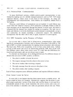
Measuring the load modulation
The precise and reproducible measurement of the load modulation signal of a
proximity coupling smart card at the antenna of a reader is very difficult due to
the weak signal. In order to avoid the resulting problems, the standard defines
a measuring bridge, which can be used to compensate the reader's (or test
transmitter's) own strong signal. The measuring arrangement for this described
in the standard consists of a field generator coil (transmission antenna) and two
parallel sensor coils in phase opposition. The two sensor coils ('reference coil'
and 'sense coil') are located on the front and back of the field generator coil,
each at the same distance from it, and are connected in phase opposition to
one another (Figures 9.36 and 9.37), so that the voltages induced in the coils
cancel each other out fully. In the unloaded state, i.e. in the absence of a load
This document was created by an unregistered ChmMagic, please go to to register it. Thanks.
from a smart card or another magnetically coupled circuit, the output voltage of
this circuit arrangement therefore tends towards zero. A low residual voltage,
which is always present between the two sensor coils as a result of
tolerance-related asymmetries, can easily be compensated by the
potentiometer.
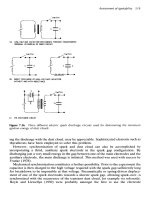
Figure 9.36: Measuring bridge circuit for measuring the load modulation
of a contactless smart card in accordance with ISO 14443
Figure 9.37: Mechanical structure of the measurement bridge,
consisting of the field generator coil (field coil), the two sensor coils
(sense and reference coil) and a smart card (PICC) as test object
(DUT) (reproduced by permission of Philips Semiconductors, Hamburg)
The following procedure should be followed for the implementation of the
measurement.
This document was created by an unregistered ChmMagic, please go to to register it. Thanks.
The smart card to be tested is first placed on the measuring bridge in the
centre of the sense coil. As a result of the current flowing through the smart
card coil, a voltage u
s
is induced in the neighbouring sense coil. This reduces
the symmetry of the measurement arrangement, so that an offset voltage is set
at the output of the measurement circuit. To prevent the falsification of the
measurement by an undefined offset voltage, the symmetry of the
measurement arrangement must be recreated with the measurement object in
place by tuning the potentiometer. The potentiometer is correctly set when the
output voltage of the measurement bridge reaches a minimum (→ 0).
After the measurement bridge has been adjusted, the reader connected to the
field coil sends a REQUEST command to the smart card under test. Now, if the
smart card begins to send a response to the reader by load modulation, the
symmetry of the measuring bridge is disrupted in time with the switching
frequency (this corresponds with the subcarrier frequency f
s
) as a result of the
modulation resistor in the smart card being switched on and off. As a result, a
subcarrier modulated HF voltage can be measured at the measurement output
of the measuring bridge. This signal is sampled over several periods using a
digital oscilloscope and then brought into the frequency range by a discrete
Fourier transformation. The amplitudes of the two modulation sidebands f
c
± f
s
that can be seen in the frequency range now serve as the quality criterion for
the load modulator and should exceed the limit value defined in ISO 14443.
The layout of the required coils, a circuit to adapt the field coil to a 50 O
transmitter output stage, and the precise mechanical arrangement of the coils
in the measuring arrangement are specified in the Annex to the standard, in
order to facilitate its duplication in the laboratory (see Section 14.4).
Reference card
As a further aid, the standard defines two different reference cards that can be
used to test the power supply of a card in the field of the reader, the transient
response and transient characteristics of the transmitter in the event of ASK
modulation, and the demodulator in the reader's receiver.
Power supply and modulation With the aid of a defined reference card it is
possible to test whether the magnetic field generated by the reader can provide
sufficient energy for the operation of a contactless smart card. The principal
circuit of such a reference card is shown in Figure 9.38. This consists primarily
of a transponder resonant circuit with adjustable resonant frequency, a bridge
rectifier, and a set of load resistors for the simulation of the data carrier.
Figure 9.38: Circuit of a reference card for testing the power supply of a
contactless smart card from the magnetic HF field of a reader
To carry out the test, the reference card is brought within the interrogation zone
This document was created by an unregistered ChmMagic, please go to to register it. Thanks.
of a reader (the spatial characteristics of the reader's interrogation field are
defined by the manufacturer of this device and should be known at the start of
the measurement). The output voltage U
meas
of the reference card is now
measured at defined resonant frequencies (f
res
= 13–19 MHz) and load
resistances (910 O, 1800 O) of the reference card. The test has been passed if
the voltage within the interrogation zone does not fall below a lower limit value
of 3 V.
Load modulation A second reference card can be used to provide a test
procedure that makes it possible to test the adherence of the receiver in the
reader to a minimum necessary sensitivity. The circuit of this test card largely
corresponds with the circuit from Figure 9.38, but it has an additional load
modulator.
To carry out the test, this reference card is brought into the interrogation zone
of a reader, this interrogation zone being defined by the manufacturer. The
reference card thus begins to transmit a continuous subcarrier signal (847 kHz
in accordance with ISO 14443) by load modulation to the reader and this signal
should be recognised by the reader within a defined interrogation zone. The
reader under test ideally possesses a test mode for this purpose, in which the
operator can be alerted to the detection of a continuous subcarrier signal.
9.2.4.3 Part 7: Test procedure for vicinity coupling smart cards
This part of the standard describes test procedures for the functional testing of
the physical interface between contactless smart cards and readers in
accordance with ISO 15693-2. The test equipment and testing procedure for
this largely correspond with the testing equipment defined in Part 6. The only
differences are the different subcarrier frequencies in the layout of the
reference card (simulation of load modulation) and the different field strengths
in operation.
[1]
The standards themselves contain no explicit information about a maximum
range; rather, they provide guide values for the simple classification of the
different card systems.
[2]
The cards consist of a complex structure consisting of up to four inductive
coupling elements and the same number of capacitive coupling elements.
[3]
Close coupling smart cards also need to be inserted into a reader for
operation, or at least precisely positioned on a stand.
[4]
Knowledge of this procedure is a prerequisite at this point. A step-by-step
introduction into the method of functioning can be found in Section 7.2.4.3.
[5]
Knowledge of this procedure is a prerequisite at this point. A step-by-step
introduction into the method of functioning can be found in Section 7.2.4.2.
[6]
The maximum frame size that a card can process is determined by the size
of the available reception buffer in the RAM memory of the microprocessor.
Particularly in low cost applications, the size of the RAM memory can be very
skimpily dimensioned.
This document was created by an unregistered ChmMagic, please go to to register it. Thanks.
9.3 ISO 69873 - Data Carriers for Tools and
Clamping Devices
This standard specifies the dimensions for contactless data carriers and their
mounting space in tools and cutters (Figure 9.39). Normally the data carriers
are placed in a quick release taper shaft in accordance with ISO 69871 or in a
retention knob in accordance with ISO 69872. The standard gives installation
examples for this.
Figure 9.39: Format of a data carrier for tools and cutters
The dimensions of a data carrier are specified in ISO 69873 as d
1
= 10 mm and
t
1
= 4.5 mm. The standard also gives the precise dimensions for the mounting
space.
This document was created by an unregistered ChmMagic, please go to to register it. Thanks.
9.4 ISO 10374 - Container Identification
This standard describes an automatic identification system for containers
based upon microwave transponders. The optical identification of containers is
described in the standard ISO 6346 and is reflected in the data record of the
transponder-based container identification.
Active — i.e. battery supported — microwave transponders are used. These
are activated by an unmodulated carrier signal in the frequency ranges
850–950 MHz and 2400–2500 MHz. The sensitivity of the transponder is
defined with an electric field strength E of a maximum of 150 mV/m. The
transponder responds by backscatter modulation (modulated reflection
cross-section), using a modified FSK subcarrier procedure (Figure 9.40). The
signal is modulated between the two subcarrier frequencies 40 kHz and 20
kHz.
Figure 9.40: Coding of data bits using the modified FSK subcarrier
procedure
The transmitted data sequence corresponds with the example in Table 9.17.
This document was created by an unregistered ChmMagic, please go to to register it. Thanks.
Table 9.17: Data sequence of a container transponder
Bit
number
DataUnitMinimum
value
Maximum
value
0–4Object
recognition
—132
5–6Reflector
type
Type code03
7–25Owner
code
alphabeticAAAAZZZZ
26–45Serial
number
numeric000000999999
46–49Check digitnumeric09
50–59LengthCentimetre12000
60–61Checksum———
62–63Structure
bits
———
64Length———
65–73HeightCentimetre1500
74–80WidthCentimetre200300
81–87Container
format
Type code0127
88–96Laden
weight
100 kg19500
97–103Tare
weight
100 kg099
104–105Reserve———
106–117Security———
118–123Data
format
code
———
124–125Check sum———
126–127Data frame
end
———
This document was created by an unregistered ChmMagic, please go to to register it. Thanks.
9.5 VDI 4470 - Anti-theft Systems for Goods
9.5.1 Part 1 - Detection gates - inspection guidelines for
customers
The VDI 4470 guideline provides a practical introduction to the inspection and
testing of installed systems for electronic article surveillance (EAS) systems
(see Figure 9.41). It describes definitions and test procedures for checking the
decisive system parameters — the false alarm rate and the detection rate.
Figure 9.41: Electronic article surveillance system in practical operation
(reproduced by permission of METO EAS-System 2002, Esselte Meto,
Hirschborn)
The term 'false alarms' is used to mean alarms that are not triggered by an
active security tag, whereas the detection rate represents the ratio of alarms to
the total number of active tags.
9.5.1.1 Ascertaining the false alarm rate
The number of false alarms should be ascertained immediately after the
installation of the EAS system during normal business. This means that all
equipment, e.g. tills and computers, are in operation. During this test phase
the products in the shop should not be fitted with security tags. During a
monitoring period of one to three weeks an observer records all alarms and the
conditions in which they occur (e.g. person in gates, cleaning, storm). Alarms
that are caused by a security tag being carried through the gates by accident
(e.g. a tag brought from another shop) are not counted.
9.5.1.2 Ascertaining the detection rate
The detection rate may be ascertained using either real or artificial products.
Real products
In this case a number of representative products vulnerable to theft are
selected and carried through the gateways by a test person in a number of
This document was created by an unregistered ChmMagic, please go to to register it. Thanks.
typical hiding places — hood, breast pocket, shoe, carrier bag, etc. When
selecting test products, remember that the material of a product (e.g. metal
surfaces) may have a quite marked effect on the detection rate.
The detection rate of a system is calculated as the proportion of alarms
triggered to the totality of tests carried out.
Artificial products
This test uses a wooden rod with a tag in the form of a label attached to the
middle. A test person carries this reference object through reference points in
the gateway that are precisely defined by VDI 4470 at a constant speed. See
Figure 9.42.
Figure 9.42: Left, measuring points in a gateway for inspection using
artificial products; right, artificial product
The detection rate of a system is calculated as the proportion of alarms
triggered to the totality of tests carried out.
9.5.1.3 Forms in VDI 4470
In order to simplify the testing of objects and to allow tests to be performed in a
consistent manner in all branches, VDI 4470 provides various forms:
Form 1: 'Test for False Alarms'
Form 2: 'Test with Real Products'
Form 3a: 'Test with Artificial Products'
Form 3b: 'Test with Artificial Products'
Form 4a: 'Test with Artificial Products'
Form 4b: 'Test with Artificial Products'
9.5.2 Part 2 - Deactivation devices, inspection guidelines for
customers
As well as the option of removing hard tags (e.g. microwave systems) at the till,
various tags can also be 'neutralised', i.e. deactivated (e.g. RF procedure,
electromagnetic procedure).
This document was created by an unregistered ChmMagic, please go to to register it. Thanks.
The objective is to achieve the complete deactivation of all tags placed in a
deactivation device, in order to avoid annoying or worrying customers by
unjustified false alarms. Deactivation devices must therefore generate optical
or acoustic signals, which indicate either a successful or an unsuccessful
deactivation.
Deactivation devices are tested during the normal activities of the shop. A
minimum of 60 protected products are required, which are checked for
functionality before and after the test. The protected products are each put
into/onto the deactivation device one after the other and the output from the
signalling device recorded.
To ascertain the deactivation rate the successfully deactivated tags are divided
by the total number of tags. This ratio must be 1, corresponding with a 100%
deactivation rate. Otherwise, the test has not been successful.
This document was created by an unregistered ChmMagic, please go to to register it. Thanks.
9.6 Item Management
9.6.1 ISO 18000 series
A whole range of new standards on the subject of item management are currently
under development. The purpose of these standards is ensure that item management
requirements are taken into account in future transponder generations. The following
standards are planned:
ISO 15961: 'RFID for Item Management: Host Interrogator; Tag
functional commands and other syntax features'
ISO 15962: 'RFID for Item Management: Data Syntax'
ISO 15963: 'Unique Identification of RF tag and Registration
Authority to manage the uniqueness'
Part 1: Numbering System
Part 2: Procedural Standard
Part 3: Use of the unique identification of RF tag
in the integrated circuit.
ISO 18000: 'RFID for Item Management: Air Interface'
Part 1: Generic Parameter for Air Interface
Communication for Globally Accepted
Frequencies
Part 2: Parameters for Air Interface
Communication below 135 kHz
Part 3: Parameters for Air Interface
Communication at 13.56 MHz
Part 4: Parameters for Air Interface
Communication at 2.45 GHz
Part 5: Parameters for Air Interface
Communication at 5.8 GHz
Part 6: Parameters for Air Interface
Communication — UHF Frequency Band
ISO 18001: 'Information technology — RFID for Item Management
— Application Requirements Profiles'
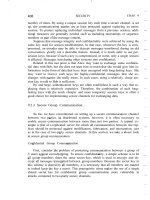
9.6.2 GTAG initiative
A further initiative, GTAG (Global Tag; see Figure 9.43) is jointly supported by the
EAN (European Article Numbering Association) and the UCC (Universal Code
Council). According to a statement by the two organisations themselves, the work of
EAN and UCC is 'to improve supply chain management and other business processes
that reduce costs and/or add value for both goods and services, EAN International and
UCC develop, establish and promote global, open standards for identification and
communication for the benefit of the users involved and the ultimate consumer'
(EAN.UCC, 1999).
This document was created by an unregistered ChmMagic, please go to to register it. Thanks.
Figure 9.43: Official logo of the GTAG initiative ()
EAN.UCC systems are used worldwide by almost a million companies from extremely
different industries for the identification of goods. The best known is the barcode,
which can be found upon all consumer goods, and which is read at the supermarket
till. The codes used, however, do not facilitate the classification of the goods, but
serve only as a unique identification (AI = Application Identifier) that allows the item to
be looked up in a database.
Electronic Document Interchange (EDI) (defined in UN/EDIFACT) represents a further
field of application of EAN.UCC systems (EAN.UCC, 2000).
The specifications currently under development facilitate the coexistence of barcode
and transponder with full compatibility from the point of view of the user. This permits
the flowing migration from barcodes to transponder systems, with the focus initially
being placed upon applications relating to transport containers and reusable
packaging (Osborne, n.d.). The requirements of such standardisation are diverse,
since all parameters of such a system must be precisely specified in order to
guarantee that the transponder can be implemented universally. The GTAG
specification of EAN.UCC will therefore deal with three layers: the transport layer, the
communication layer, and the application layer.
The transport layer describes the physical interface between
transponder and reader, i.e. transmission frequency, modulation
frequency and data rate. The most important factor here is the
selection of a suitable frequency so that EAN.UCC systems can be
used worldwide without restrictions and can be manufactured at a
low cost. Furthermore, the GTAG specification for the transport layer
will flow into the future ISO 18000-6 standard (Osborne, n.d.).
The communication layer describes the structure of the data blocks
that are exchanged between transponder and reader. This also
includes the definition of an anticollision procedure, plus the
description of commands for the reading or writing of the
transponder.
The application layer includes the organisation and structure of the
application data stored on the transponder. GTAG transponders will
include at least an EAN.UCC Application Identifier (AI) (EAN.UCC,
2000). This AI was developed for data carriers with low storage
capacity (barcodes). RFID transponders, however, permit additional
data and provide the option of changing data in the memory, so that
the GTAG specification will contain optional data fields and options.
The completion of the GTAG specification is planned for 2002 at the earliest. For this
reason, only a brief overview of the technical details can be given in what follows.
9.6.2.1 GTAG transport layer (physical layer)
In order to be able to fulfil the requirements of range and transmission speed imposed
on GTAG, the UHF frequency range has been selected for the transponders.
However, one problem in this frequency range is local differences in frequency
regulations. For example, 4 W transmission power is available for RFID systems in the
frequency range 910–928 MHz in America. In Europe, on the other hand, the ERO
(European Radio-communications Organisation) is currently being lobbied to allocate
2 W transmission power to the frequency range 865.6-867.6 MHz. Due to the different
frequency ranges of the readers, GTAG transponders are designed so that they can
be interrogated by a reader over the entire 862–928 MHz frequency range. It makes
This document was created by an unregistered ChmMagic, please go to to register it. Thanks.
no difference in the case of backscatter transponders whether the reader uses a
fixed transmission frequency (Europe) or changes the transmission frequency at
periodic intervals (frequency hopping spread spectrum, USA and Canada).
Table 9.18: Provisional technical parameters of a GTAG reader
ParameterValue
Transmission frequency and power
of the reader
862–928 MHz, 2 –4 W (depending
upon regulations)
Downlink40% ASK Pulse Time Modulation, '1
of $' coding
Anticollision procedureDynamic slotted ALOHA procedure
Maximum number of transponders
in the field
250
Table 9.19: Provisional technical parameters of a GTAG transponder
ParameterValue
Minimum frequency range of
transponder
862–928 MHz
UplinkBackscatter (Delta RCS), bi-phase
code
Bit rateSlow: 10 Kbit/s, fast: 40 Kbit/s
Delta RCS
>0.005 m
2
9.6.2.2 GTAG communication and application layer
The GTAG communication and application layers are described in the MP&PR
specification (minimum protocol and performance requirement). The MP&PR
(GTAG-RP) defines the coding of data on the contactless transmission path, the
construction of a communication relationship between reader and transponder
(anticollision and polling), the memory organisation of a transponder, and numerous
commands for the effective reading and writing of the transponder.
The memory of a GTAG transponder is organised into blocks each of 128 bits (16
bytes). The GTAG specification initially permits only the addressing of a maximum of
32 pages, so that a maximum of 512 bytes can be addressed. However, it should be
assumed that for most applications it is sufficient for a data set identical to the barcode
in accordance with EAN/UCC-128 to be stored in a page of the transponder.
This document was created by an unregistered ChmMagic, please go to to register it. Thanks.
Chapter 10: The Architecture of Electronic Data
Carriers
Overview
Before we describe the functionality of the data carriers used in RFID systems we
must first differentiate between two fundamental operating principles: there are
electronic data carriers based upon integrated circuits (microchips) and data carriers
that exploit physical effects for data storage. Both 1-bit transponders and surface
wave components belong to the latter category.
Electronic data carriers are further subdivided into data carriers with a pure memory
function and those that incorporate a programmable microprocessor (Figure 10.1).
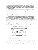
Figure 10.1: Overview of the different operating principles used in RFID data
carriers
This chapter deals exclusively with the functionality of electronic data carriers. The
simple functionality of physical data carriers has already been described in Chapter 3.
This document was created by an unregistered ChmMagic, please go to to register it. Thanks.
10.1 Transponder with Memory Function
Transponders with a memory function range from the simple read-only transponder to
the high end transponder with intelligent cryptological functions (Figure 10.2).
Figure 10.2: Block diagram of an RFID data carrier with a memory function
Transponders with a memory function contain RAM, ROM, EEPROM or FRAM and
an HF interface to provide the power supply and permit communication with the
reader. The main distinguishing characteristic of this family of transponders is the
realisation of address and security logic on the chip using a state machine.
10.1.1 HF interface
The HF interface forms the interface between the analogue, high frequency
transmission channel from the reader to the transponder and the digital circuitry of the
transponder. The HF interface therefore performs the functions of a classical modem
(modulator-demodulator) used for analogue data transmission via telephone lines.
The modulated HF signal from the reader is reconstructed in the HF interface by
demodulation to create a digital serial data stream for reprocessing in the address and
security logic. A clock-pulse generation circuit generates the system clock for the data
carrier from the carrier frequency of the HF field.
The HF interface incorporates a load modulator or backscatter modulator (or an
alternative procedure, e.g. frequency divider), controlled by the digital data being
transmitted, to return data to the reader (Figure 10.3).
Figure 10.3: Block diagram of the HF interface of an inductively coupled
transponder with a load modulator
This document was created by an unregistered ChmMagic, please go to to register it. Thanks.
Passive transponders, i.e. transponders that do not have their own power supply, are
supplied with energy via the HF field of the reader. To achieve this, the HF interface
draws current from the transponder antenna, which is rectified and supplied to the
chip as a regulated supply voltage.
10.1.1.1 Example circuit - load modulation with subcarrier
The principal basic circuit of a load modulator is shown in Figure 10.4. This generates
an ohmic load modulation using an ASK or FSK modulated subcarrier. The frequency
of the subcarrier and the baud rates are in accordance with the specifications of the
standard ISO 15693 (Vicinity coupling smart cards).
Figure 10.4: Generation of a load modulation with modulated subcarrier— the
subcarrier frequency is generated by a binary division of the carrier frequency
of the RFID system. The subcarrier signal itself is initially ASK or FSK
modulated (switch position ASK/FSK) by the Manchester coded data stream,
while the modulation resistor in the transponder is finally switched on and off
in time with the modulated subcarrier signal
The high-frequency input voltage u
2
of the data carrier (transponder chip) serves as
the time basis of the HF interface and is passed to the input of a binary divider. The
frequencies specified in the standard for the subcarrier and the baud rate can be
derived from the single binary division of the 13.56 MHz input signal (Table 10.1).
Table 10.1: The clock frequencies required in the HF interface are generated by the
binary division of the 13.56 MHz carrier signal
Splitter NFrequencyUse
1/28485 kHz
φ2 of the FSK subcarrier
1/32423 kHz
φ1 of the FSK subcarrier, plus ASK subcarrier
1/51226.48 kHzBit clock signal for high baud rate
1/20486.62 kHzBit clock signal for slow baud rate
The serial data to be transmitted is first transferred to a Manchester generator. This
allows the baud rate of the baseband signal to be adjusted between two values. The
Manchester coded baseband signal is now used to switch between the two subcarrier
frequencies f
1
and f
2
using the '1' and '0' levels of the signal, in order to generate an
FSK modulated subcarrier signal. If the clock signal f
2
is interrupted, this results in an
ASK modulated subcarrier signal, which means that it is very simple to switch
between ASK and FSK modulation. The modulated subcarrier signal is now
This document was created by an unregistered ChmMagic, please go to to register it. Thanks.
transferred to switch S, so that the modulation resistor of the load modulator can be
switched on and off in time with the subcarrier frequency.
10.1.1.2 Example circuit - HF interface for ISO 14443 transponder
The circuit in Figure 10.5 provides a further example of the layout of a HF interface.
This was originally a simulator for contactless smart cards in accordance with ISO
14443, which can be used to simulate the data transmission from the smart card to a
reader by load modulation. The circuit was taken from a proposal by Motorola for a
contactless smart card in ISO 10373-6 (Baddeley and Ruiz, 1998).
Figure 10.5: Example circuit of a HF interface in accordance with ISO 14443
A complete layout is available for the duplication of this test card (see Section 14.4.1).
The circuit is built upon an FR4 printed circuit board. The transponder coil is realised
in the form of a large area conductor loop with four windings of a printed conductor.
The dimensions of the transponder coil correspond with the ratios in a real smart card.
The transponder resonant circuit of the test card is made up of the transponder coil L
1
and the trimming capacitor CV
1
. The resonant frequency of the transponder resonant
circuit should be tuned to the transmission frequency of the reader, 13.56 MHz
(compare Section 4.1.11.2). The HF voltage present at the transponder resonant
circuit is rectified in the bridge rectifier D
1
- D
4
and maintained at approximately 3 V by
the zener diode D
6
for the power supply to the test card.
The binary divider U
1
derives the required system clocks of 847.5 kHz (subcarrier,
divider 1/16) and 105.93 kHz (baud rate, divider 1/128) from the carrier frequency
13.56 MHz.
The circuit made up of U
2
and U
3
is used for the ASK or BPSK modulation of the
subcarrier signal (847.5 kHz) with the Manchester or NRZ coded data stream (jumper
1-4). In addition to the simple infinite bit sequences 1111 and 1010, the supply of an
external data stream (jumper 10) is also possible. The test smart card thus supports
both procedures for data transfer between smart card and reader defined in ISO
14443-2.
Either a capacitive (C
4
, C
5
) or an ohmic (R
9
) load modulation can be selected. The
'open collector' driver U
4
serves as the output stage ('switch') for the load modulator.
The demodulation of a data stream transmitted from the reader is not provided in this
circuit. However, a very simple extension of the circuit (see Figure 10.6) facilitates the
demodulation of at least a 100% ASK modulated signal. This requires only an
additional diode to rectify the HF voltage of the transponder resonant circuit. The
time constant τ = R · C should be dimensioned such that the carrier frequency (13.56
This document was created by an unregistered ChmMagic, please go to to register it. Thanks.
MHz) is still effectively filtered out, but the modulation pulse (t
pulse
= 3 µs in
accordance with ISO 14443-2) is retained as far as is possible.
Figure 10.6: A 100% ASK modulation can be simply demodulated by an
additional diode
10.1.2 Address and security logic
The address and security logic forms the heart of the data carrier and controls all
processes on the chip (Figure 10.7).
Figure 10.7: Block diagram of address and security logic module
The power on logic ensures that the data carrier takes on a defined state as soon as it
receives an adequate power supply upon entering the HF field of a reader. Special I/O
registers perform the data exchange with the reader. An optional cryptological unit is
required for authentication, data encryption and key administration.
The data memory, which comprises a ROM for permanent data such as serial
numbers, and EEPROM or FRAM is connected to the address and security logic via
the address and data bus inside the chip.
The system clock required for sequence control and system synchronisation is
derived from the HF field by the HF interface and supplied to the address and security
logic module. The state-dependent control of all procedures is performed by a state
machine ('hard-wired software'). The complexity that can be achieved using state
machines comfortably equals the performance of microprocessors (high end
transponders). However the 'programme sequence' of these machines is determined
This document was created by an unregistered ChmMagic, please go to to register it. Thanks.
by the chip design. The functionality can only be changed or modified by modifying
the chip design and this type of arrangement is thus only of interest for very large
production runs.
10.1.2.1 State machine
A state machine (also switching device, Mealy machine) is an arrangement used for
executing logic operations, which also has the capability of storing variable states
(Figure 10.8). The output variable Y depends upon both the input variable X and what
has gone before, which is represented by the switching state of flip-flops (Tietze and
Schenk, 1985).
Figure 10.8: Block diagram of a state machine, consisting of the state memory
and a backcoupled switching network
The state machine therefore passes through different states, which can be clearly
represented in a state diagram (Figure 10.9). Each possible state S
Z
of the system is
represented by a circle. The transition from this state into another is represented by
an arrow. The arrow caption indicates the conditions that the transition takes place
under. An arrow with no caption indicates an unspecified transition (power on → S
1
).
The current new state S
Z
(t + 1) is determined primarily by the old state S
Z
(t) and,
secondly, by the input variable x
i
.
Figure 10.9: Example of a simple state diagram to describe a state machine
The order in which the states occur may be influenced by the input variable x. If the
This document was created by an unregistered ChmMagic, please go to to register it. Thanks.
system is in state S
Z
and the transition conditions that could cause it to leave this state
are not fulfilled, the system remains in this state.
A switching network performs the required classification: If the state variable Z(t) and
the input variable are fed into its inputs, then the new state Z(t + 1) will occur at the
output (Figure 10.8). When the next timing signal is received this state is transferred
to the output of (transition triggered) flip-flops and thus becomes the new system state
S(t + 1) of the state machine.
10.1.3 Memory architecture
10.1.3.1 Read-only transponder
This type of transponder represents the low-end, low-cost segment of the range of
RFID data carriers. As soon as a read-only transponder enters the interrogation zone
of a reader it begins to continuously transmit its own identification number (Figure
10.10). This identification number is normally a simple serial number of a few bytes
with a check digit attached. Normally, the chip manufacturer guarantees that each
serial number is only used once. More complex codes are also possible for special
functions.
Figure 10.10: Block diagram of a read-only transponder. When the
transponder enters the interrogation zone of a reader a counter begins to
interrogate all addresses of the internal memory (PROM) sequentially. The
data output of the memory is connected to a load modulator which is set to
the baseband code of the binary code (modulator). In this manner the entire
content of the memory (128-bit serial number) can be emitted cyclically as a
serial data stream (reproduced by permission of TEMIC Semiconductor
GmbH, Heilbronn)
The transponder's unique identification number is incorporated into the transponder
during chip manufacture. The user cannot alter this serial number, nor any data on the
chip.
Communication with the reader is unidirectional, with the transponder sending its
identification number to the reader continuously. Data transmission from the reader to
the transponder is not possible. However, because of the simple layout of the data
carrier and reader, read-only transponders can be manufactured extremely cheaply.
Read-only transponders are used in price-sensitive applications that do not require
the option of storing data in the transponder. The classic fields of application are
therefore animal identification, access control and industrial automation with central
data management.
This document was created by an unregistered ChmMagic, please go to to register it. Thanks.