rfid handbook fundamentals and applications in contactless smart cards and identification second edition phần 8 pps
Bạn đang xem bản rút gọn của tài liệu. Xem và tải ngay bản đầy đủ của tài liệu tại đây (2.52 MB, 52 trang )
Figure 13.20: Fitting a read antenna for the Euro balise onto a tractive unit
(reproduced by permission of Siemens Verkehrstechnik, Braunschweig)
Four different balise types have been developed by Siemens:
Type 1 transmits a permanently programmed telegram.
Type 2 transmits a telegram that can be programmed by the user
via the contactless interface. For example, this may be line data
such as gradient and speed profiles.
Type 3 transmits a telegram generated by a line device (transparent
balise). Type 3 is primarily used in connection with signals.
Type 4 makes it possible to download data as vehicles drive past.
13.5.2 International container transport
International freight transport containers have been identified using the alphanumeric
identification procedure specified in the international standard ISO 6346 since the end
of the 1960s. This identification mark consists of four letters, the owner's code, a
six-digit numeric serial number and a test digit, and is painted onto the outside of the
container at a specified position (Figure 13.21).
Figure 13.21: Container identification mark, consisting of owner's code, serial
number and a test digit
Almost all of the 7 million containers in use worldwide employ the identification
procedures specified in this standard and thus have their own, unmistakable
identification number. The process of manually recording the container identification
number and entering it into the computer of a transhipment plant is extremely
susceptible to errors. Up to 30% of identifications have been falsely recorded at some
point. Automatic data transmission can help to solve this problem by the reading of a
transponder attached to the container. In 1991 the international standard ISO 10374
was drawn up to provide a basis for the worldwide use of this technology.
The bands 888 to 889 MHz and 902 to 928 MHz (North America) and 2.4 to 2.5 GHz
(Europe) are used as the operating frequencies for the transponders. The
This document was created by an unregistered ChmMagic, please go to to register it. Thanks.
transponders must respond on all three of the frequency ranges used. Backscatter
modulation (modulated reflection cross-section) with an FSK modulated subcarrier is
the procedure used for the data transfer from the container to the reader. The
subcarrier frequencies are 20 kHz and 40 kHz. A total of 128 bits (16 bytes) are
transmitted within just 2 ms.
The reader's signal is not modulated (read-only transponder). The specified maximum
reader distance is 13 m.
ISO 10374 specifies the following information that can be stored in the transponder:
owner's code, serial number and test digit;
container length, height and width;
container type, i.e. suitcase container, tank container, open top
container and others;
laden and tare weight.
A battery provides the power supply to the electronic data carrier in the transponder
(active transponder). The lifetime of the battery corresponds with the lifetime of the
container itself, i.e. around 10 to 15 years.
The same technology is used in the identification of goods wagons in North American
and European railway transport. A European standard is in preparation for the
automatic identification of European interchangeable containers (Siedelmann, 1997).
This document was created by an unregistered ChmMagic, please go to to register it. Thanks.
13.6 Animal Identification
13.6.1 Stock keeping
Electronic identification systems have been used in stock keeping for almost 20 years
(Kern and Wendl, 1997) and are now state of the art in Europe. In addition to internal
applications for automatic feeding and calculating productivity, these systems can also
be used in inter-company identification, for the control of epidemics and quality
assurance and for tracing the origin of animals. The required unified data transmission
and coding procedures are provided by the 1996 ISO standards 11784 and 11785
(see Section 9.1). The specified frequency is 134.2 kHz, and FDX and SEQ
transponders can both be used. A size comparison of the various transponders is
given in Figure 13.22.
Figure 13.22: Size comparison of different variants of electronic animal
identification transponders— collar transponder, rumen bolus, ear tags with
transponder, injectible transponder (reproduced by permission of Dr Michael
Klindtworth, Bayrische Landesanstalt für Landtechnik, Freising)
There are four basic procedures for attaching the transponder to the animal: collar
transponders, ear tag transponders, injectible transponders and the so-called bolus
(Figure 13.23). Cross-sections of different types of transponders are shown in Figure
13.24.
This document was created by an unregistered ChmMagic, please go to to register it. Thanks.
Figure 13.23: The options for attaching the transponder to a cow
Figure 13.24: Cross-sections of various transponder designs for animal
identification (reproduced by permission of Dr Georg Wendl, Landtechnischer
Verein in Bayern e.V., Freising)
Collar transponders can be easily transferred from one animal to another. This permits
the use of this system within a company. Possible applications are automatic feeding
in a feeding stall and measuring milk output.
Ear tags incorporating an RFID transponder compete with the much cheaper barcode
ear tags. However, the latter are not suitable for total automation, because barcode
ear tags must be passed a few centimetres from a hand reader to identify the animal.
RFID ear tags, on the other hand, can be read at a distance of up to 1 m.
Injectible transponders were first used around 10 years ago. In this system, the
transponder is placed under the animal's skin using a special tool. A fixed connection
is thereby made between the animal's body and the transponder, which can only be
removed by an operation. This allows the use of implants in inter-company
applications, such as the verification of origin and the control of epidemics.
The implant is in the form of a glass transponder of 10, 20 or 30 mm in length (Figure
13.25). The transponder is supplied in a sterile package or with a dose of disinfectant.
The dimensions of the glass transponder are amazingly small, considering that they
contain the chip and a coil wound around a ferrite rod. A typical format is 23.1 mm ×
3.85 mm (Texas Instruments, 1996).
This document was created by an unregistered ChmMagic, please go to to register it. Thanks.
Figure 13.25: Enlargement of different types of glass transponder (reproduced
by permission of Texas Instruments)
Various instruments and injection needles are available for performing the injection:
'Single-shot' devices use closed hollow needles ('O' shape), which
are loaded individually. Single use needles containing transponders
in a sterile package are also available. The hollow needles are
sharpened at the tip, so that the skin of the animal is ripped open
when the needle is inserted. The blunt upper part of the needle tip
presses the cut flap of skin to one side so that the insertion point is
covered up again when the needle has been removed, allowing the
wound to heal quickly (Kern, 1994).
The 'Multi-shot' device has a magazine for several transponders,
thus dispensing with the need to load the device. Open-ended
hollow needles ('U' shaped) are used, as these are easier to clean,
disinfect and check than closed hollow needles and can therefore
be used several times.
The injection does not hurt the animal and can be carried out by practised laymen.
However, attention should be given to hygiene to ensure that the wound heals safely.
An injected transponder represents a foreign body in the animal's tissues. This can
lead to problems in the locational stability of the transponder within the animal's body,
and may therefore cause problems when reading the transponder. From our
experience of war injuries we know that shrapnel can often wander several decimetres
through the body during a person's lifetime. An injected transponder can also 'wander'
around. To solve this problem, the Bayerischen Landesanstalt für Landtechnik in
Weihenstephan, a branch of the Technical University in Munich, has been
investigating various injection sites since 1989 (Kern, 1994). As a result of these
studies, injection under the scutulum is currently favoured over the use of the right ear,
with the injection being directed towards the occipital bone (Figure 13.26). According
to findings of the Landanstalt, this position is also suitable for measuring the animal's
body temperature.
This document was created by an unregistered ChmMagic, please go to to register it. Thanks.
Figure 13.26: Injection of a transponder under the scutulum of a cow
(reproduced by permission of Dr Georg Wendl, Landtechnischer Verein in
Bayern e.V., Freising)
The so-called bolus is a very useful method of fitting the transponder. The bolus is a
transponder mounted in an acid resistant, cylindrical housing, which may be made of a
ceramic material. The bolus is deposited in the rumen, the omasum that is present in
all ruminants, via the gullet using a sensor. Under normal circumstances the bolus
remains in the stomach for the animal's entire lifetime. A particular advantage of this
method is the simple introduction of the transponder into the animal's body, and in
particular the fact that it does not cause any injury to the animal. The removal of the
bolus in the slaughter house is also simpler than the location and removal of an
injected transponder (Kern and Wendl, 1997). See Figures 13.27–13.30.
It is clear that the injected transponder and the bolus are the only foolproof
identification systems available to stock keepers. A more detailed comparison of the
two systems (Kern and Wendl, 1997) shows that the bolus is particularly suited for use
in the extensive type of stock keeping that is prevalent in Australia or South America.
In intensive stock keeping methods, commonly used in central Europe, both systems
appear to be suitable. The degree to which bolus, injection or even RFID ear tags will
become the industry standard means of identification remains to be seen. See Geers
et al. (1997), Kern (1997) and Klindtworth (1998) for further information on the material
in this section.
13.6.2 Carrier pigeon races
Participating in races is a significant part of carrier pigeon breeding. In these races,
hundreds of pigeons are released at the same place and time, at a location a long
distance from their home. Pigeons are judged by the time they take to return home
from the point where they were released. One problem is the reliable recording
(confirmation) of arrival times, because in the past the breeders themselves recorded
the times using a mechanical confirmation clock.
This document was created by an unregistered ChmMagic, please go to to register it. Thanks.
Figure 13.27: Automatic identification and calculation of milk production in the
milking booth (reproduced by permission of Dr Georg Wendl,
Landtechnischer Verein in Bayern e.V., Freising)
Figure 13.28: Output related dosing of concentrated feed at an automatic feed
booth for milk cows. In the illustration the cow is identified by the transponder
at its neck (reproduced by permission of Dr Georg Wendl, Landtechnischer
Verein in Bayern e.V., Freising)
This document was created by an unregistered ChmMagic, please go to to register it. Thanks.
Figure 13.29: Oral application of a bolus transponder (reproduced by
permission of Dr Michael Klindtworth, Bayerische Landesanstalt für
Landtechnik, Freising)
Figure 13.30: Example of automated animal recognition in practice— grouping
calves properly for feeding often requires much time and effort. Here a
machine takes on this task— the animals can receive an individually
adjustable amount of milk in several small portions (reproduced by
permission of Dr Michael Klindtworth, Bayerische Landesanstalt für
Landtechnik, Freising)
To solve the problem of timing, the pigeons are fitted with rings that incorporate a
read-only transponder based upon a glass transponder. As the pigeons are loaded
onto the transporter for transport to the release site, the serial numbers of the
transponders are read to register the animals for participation in the race. Upon the
pigeon's arrival at its home pigeonry a reader installed in the pigeonhole records the
serial number and stores it, together with the precise arrival time, in a portable control
unit. Judging takes place by the reading of the devices at the operating point (Figure
This document was created by an unregistered ChmMagic, please go to to register it. Thanks.
13.31).
Figure 13.31: Pigeon upon arrival at its own pigeonry. Upon the pigeon's
entry, the transponder in the ring is read (reproduced by permission of Legic
Identsystems, CH-Wetzikon)
However, the ingenuity of some of the breeders was greatly underestimated when this
system was first introduced. It was not long before some breeders were not only able
to read the transponder codes from the pigeon ring, but could also fool the reader
using a simulation device in the home pigeonry. The technology involved was fairly
simple — all that was required was an extremely simple read-only transponder, whose
'serial number' could be altered using external DIP switches. Thus, some breeders
were able to significantly accelerate the 'flight speeds' of their champions.
An effective measure to protect against such attempts at fraud is the incorporation of
an additional writable EEPROM memory into the transponder. The memory size is just
1 byte to keep the chip size and cost of circuitry low (Figure 13.32). Before the start, a
previously determined random number, for which there are 2
8
= 256 possibilities, is
written to this byte in the transponder at the headquarters. It is crucial that the breeder
does not have access to his bird while it is being transported to the release site after
the transponder has been programmed. This prevents the random number from being
read. When the pigeon reaches its home pigeonry, its arrival is confirmed
electronically. The time, together with the transponder code and the secret random
number are stored. When the records are evaluated at the headquarters, the random
number read upon arrival is compared with the number programmed at the start. The
measured times are only validated if the two figures are identical, otherwise it is
assumed that an attempted fraud has taken place.
Figure 13.32: The generation of a random number which is written to the
transponder before the start protects against attempted fraud
This document was created by an unregistered ChmMagic, please go to to register it. Thanks.
The procedure described is clearly adequate to successfully prevent attempted fraud.
With 256 possibilities for the random number the probability that this will be guessed
correctly in a single attempt is only 0.4%.
In order to keep the weight and dimensions of the pigeon transponder low, glass
transponders are used in this application, which are cast into a plastic ring. These
plastic rings can be fastened to the pigeon's leg without hindering the animal or
causing it any discomfort (Figure 13.33).
Figure 13.33: Typical antenna of an electronic confirmation system. The
transponder on the pigeon's left leg is also clearly visible (reproduced by
permission of Deister Electronik, Barsinghausen)
This document was created by an unregistered ChmMagic, please go to to register it. Thanks.
13.7 Electronic Immobilisation
The sharp rise in vehicle theft at the beginning of the 1990s — particularly in Germany
— boosted the demand for effective anti-theft systems. Battery-operated remote
control devices with a range of 5–20 m had already been available on the market for
years. These are small infrared or RF transmitters operating on the UHF frequency
433.92 MHz, which are primarily used to control the central locking system and an
integral alarm. An (electronic) immobiliser may also be coupled to the remote control
function. In this type of anti-theft device, however, the mechanical lock can still be
used to gain access to the vehicle — in case the remote control device fails to work
due to the failure of the battery in the transmitter. This is the greatest weakness of this
type of system, as the system cannot check whether the mechanical key is genuine.
Vehicles secured in this manner can therefore be opened with a suitable tool (e.g.
picklock) and started up by an unauthorised person.
Since the middle of the 1990s, transponder technology has provided a solution that
can be used to check the authenticity, i.e. the genuineness, of the key. This solution
has proved ideal for the realisation of the electronic immobilisation function via the
ignition lock. Today, transponder technology is usually combined with the
above-mentioned remote control system: the remote control operates the vehicle's
central locking and alarm system, while transponder technology performs the
immobilisation function.
13.7.1 The functionality of an immobilisation system
In an electronic immobilisation system a mechanical ignition key is combined with a
transponder. The miniature transponder with a ferrite antenna is incorporated directly
into the top of the key (see Figure 13.34). The antenna is integrated into the ignition
lock (Figure 13.35).
This document was created by an unregistered ChmMagic, please go to to register it. Thanks.
Figure 13.34: Ignition key with integral transponder (reproduced by permission
of Philips Electronics N.V.)
Figure 13.35: The antenna of the electronic immobilisation system is
integrated directly into the ignition lock (reproduced by permission of Deister
Elektronik, Barsinghausen)
The reader antenna is integrated into the ignition lock in such a manner that when the
ignition key is inserted, the (inductive) coupling between reader antenna and
transponder coil is optimised. The transponder is supplied with energy via the
inductive coupling and is therefore totally maintenance free. Electronic immobilisers
typically operate at a transmission frequency in the LF range 100–135 kHz. ASK
modulation is the preferred modulation procedure for the data transfer to the
transponder, because it allows reader and transponder to be manufactured very
cheaply (Doerfler, 1994). Load modulation is the only procedure used for data
transmission from the transponder to the reader.
When the ignition key is turned in the ignition lock to start the vehicle, the reader is
activated and data is exchanged with the transponder in the ignition key. Three
procedures are employed to check the authenticity of the key:
Checking of an individual serial number. In almost all transponder
systems the transponder has a simple individual serial number
(unique number). If the normal number of binary positions is used,
significantly more different codes are available than worldwide car
production (2
32
= 4.3 billion, 2
48
= 2.8 × 10
14
). Very simple systems
(first generation immobilisation) read the transponder's serial
number and compare this with a reference number stored in the
reader. If the two numbers are identical the motor electronics are
released. The problem here is the fact that the transponder serial
number is not protected against unauthorised reading and, in
theory, this serial number could be read by an attacker and copied
to a special transponder with a writable serial number.
Rolling code procedure. Every time the key is operated a new
number is written to the key transponder's memory. This number is
generated by a pseudo-random generator in the vehicle reader. It
is therefore impossible to duplicate the transponder if this system is
This document was created by an unregistered ChmMagic, please go to to register it. Thanks.
used. If several keys are used with one vehicle then each key runs
through its own pseudo-random sequence.
Cryptographic procedures (authentication) with fixed keys. The use
of cryptographic procedures offers much greater security (second
generation immobilisation). In the authentication sequence
(challenge response) knowledge of a secret (binary) key is checked,
without this key being transmitted (see Chapter 8). In vehicle
applications, however, unilateral authentication of the key
transponder by the reader in the ignition lock is sufficient.
The RFID reader now communicates with the vehicle's motor electronics, although this
communication is protected by cryptographic procedures. The motor electronics
control all important vehicle functions, in particular the ignition system and fuel system.
Simply short circuiting or disconnecting certain cables and wires is no longer sufficient
to circumvent an electronic immobilisation system (Figure 13.36). Even attempting to
fool the motor electronics by inserting another ignition key of the same type into the
ignition lock is bound to fail because of the authentication procedure between reader
and motor electronics. Only the vehicle's own key has the correct (binary) key to
successfully complete the authentication sequence with the motor electronics.
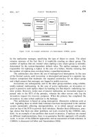
Figure 13.36: Functional group of an electronic immobilisation system. The
RFID reader authenticates itself with regard to the motor electronics to
prevent the manipulation of the reader. The motor electronics control the
ignition, fuel and starter and thus can block all the crucial functions of the
vehicle (reproduced by permission of Texas Instruments)
The installation of such an electronic immobiliser to the engine management system
can only be performed at the factory by the vehicle manufacturer, thus guaranteeing
optimal interaction between engine control system and security device. The individual
key data is programmed in the factory by laser programmable fuses on the chip or by
writing to an OTP-EEPROM. The vehicle manufacturer is also responsible for
implementing appropriate security measures to prevent criminals from unlawfully
procuring replacement parts (Wolff, 1994). With few exceptions, electronic
immobilisation systems have been fitted to all new cars as standard since the
beginning of 1995 (Anselm, 1996). See Figure 13.37.
This document was created by an unregistered ChmMagic, please go to to register it. Thanks.
Figure 13.37: Electronic immobiliser and door locking system are integrated
into a transponder in the ignition key. In the ignition lock and in the vicinity of
the doors (passive entry) the transponder is supplied with power by inductive
coupling. At greater distances (remote keyless entry) the transponder is
supplied with power from a battery (round cell in the top of the key) at the
push of a button ('OPEN') (reproduced by permission of Texas Instruments)
13.7.2 Brief success story
In 1989 the Berlin wall and the border to Eastern Europe were opened, and the years
following 1989 were characterised by dramatic increases in vehicle thefts in Germany.
From 48 514 thefts in 1988, the figure had risen to 144 057 thefts just five years later
in 1993 — almost a threefold increase. This prompted the German Federal
Supervisory Office for Insurance to declare a change to the General Insurance
Conditions for Motor Vehicle Insurance (AKB) at the beginning of 1993.
According to the old conditions, vehicle owners with fully comprehensive insurance
could, under certain conditions, claim the full price for a new car if their vehicle was
stolen, although the resale value of the stolen vehicle and thus the damage suffered
was significantly less than this (Wolff, 1994). The value of a vehicle after just a few
months falls a long way short of the price of a new car.
Under the new conditions, only the cost of replacing the vehicle, i.e. its actual market
value, is refunded in the case of loss (accident, theft, ). Furthermore, if the loss is
due to theft an excess is deducted from the payment, which may be waived if the
vehicle is fitted with an approved anti-theft device (Wolff, 1994). The vehicle owner's
own interest in having an effective anti-theft device was significantly increased by the
new insurance conditions.
The effectiveness of electronic immobilisation has been clearly demonstrated by the
decreasing trend in vehicle thefts in Germany. In 1994 there had already been a slight
fall of about 2000 to 142 113, compared to the record figure from 1993. Two years
later — 1996 — 110 764 thefts were reported. This represents a fall of 22% in just 2
years.
Another factor is that since 1995 electronic immobilisers have been fitted to all new
cars — with a few exceptions — in the factory as standard. If we consider vehicles
secured in this manner alone, then we can expect a reduction in the theft rate by a
factor of 40(!).
In this connection it is interesting to examine investigations by insurance companies
into vehicle thefts where electronic immobilisers were fitted (Anselm, 1995, 1996;
Caspers, 1997).
This document was created by an unregistered ChmMagic, please go to to register it. Thanks.
Of 147 stolen vehicles in 1996, 70% of thefts were performed using the original key,
which the thief had obtained by breaking into homes, garages and workshops, or by
stealing from offices, bags and changing rooms or by the fraudulent renting and
misappropriation of rental or demonstration cars. In the remaining 30% of cases, the
vehicles either disappeared under circumstances that indicated the cooperation of the
owner (without this being proved in individual cases), or vehicles were loaded onto
lorries and transported away by professionals.
There has not been one case since 1995 where the electronic immobiliser has been
'cracked' or beaten by a thief.
13.7.3 Predictions
The next generation of immobilisers will also incorporate a passive, cryptologically
secured access system. In this system, a reader will be fitted in each of the vehicle's
doors. Sequential systems (TIRIS®) will be able to achieve a remote range, in which
the transponder is supplied by a battery, so that the vehicle's central locking system
can be operated from a greater distance away. This is similar in its function to the
combination of an immobiliser and central locking remote control on a single
transponder.
This document was created by an unregistered ChmMagic, please go to to register it. Thanks.
13.8 Container Identification
13.8.1 Gas bottles and chemical containers
Gas and chemicals are transported in high quality rented containers. Selecting the
wrong bottle during refilling or use could have fatal consequences. In addition to
product specific sealing systems, a clear identification system can help to prevent
such errors. A machine readable identification system gives additional protection
(Braunkohle, 1997). A large proportion of containers supplied today are identified by
barcodes. However, in industrial use the popular barcode system is not reliable
enough, and its short lifetime means that maintenance is expensive.
Transponders also have a much higher storage capacity than conventional barcodes.
Therefore additional information can be attached to the containers such as owner
details, contents, volumes, maximum filling pressure and analysis data. The
transponder data can also be changed at will, and security mechanisms
(authentication) can be used to prevent unauthorised writing or reading of the stored
data.
Inductively coupled transponders operating in the frequency range <135 kHz are
used. The transponder coil is housed in a ferrite shell to shield it from the metal
surface (see also Section 4.1.12.3).
The manufacturing process for the transponders is subject to exacting standards: the
transponders are designed for an extended temperature range from —40 °C to +120
°C; their height is just 3 mm. These transponders must also be resistant to damp,
impact, vibrations, dirt, radiation and acids (Bührlen, 1995).
Because the transmission procedure for transponders used in container identification
has not been standardised, various systems are available. Because a device has
been developed that can process all the transponder types used, the user can choose
between the different transponder systems — or may even use a combination of
different systems.
Mobile and stationary readers are available (Figures 13.38 and 13.39). Stationary
readers can be incorporated into a production system which automatically recognises
and rejects wrong containers. After filling, the current product data is automatically
stored on the transponder. When this system is used in combination with database
management, the number of containers used by a customer for a given gas
consumption can be drastically reduced, because excessive standing times or storage
periods can be easily recognised and corrected. In addition, all the stations that the
container passes through on its way to the customer and back can be automatically
recorded by the use of additional readers. So, for example, it is possible to trace
customers who return the containers dirty (Braunkohle, 1997). For gas, where there
is not much potential for product differentiation between manufacturers, the associated
cost savings can convey an important competitive advantage (Bührlen, 1995).
This document was created by an unregistered ChmMagic, please go to to register it. Thanks.
Figure 13.38: Identification of gas bottles using a portable reader. The reader
(scemtec SIH3) is designed to function with transponders from different
manufacturers (reproduced by permission of Messer Griesheim)
Figure 13.39: Portable antenna for reading inductively coupled transponders
mounted on gas bottles or other containers (reproduced by permission of
SCEMTEC Transponder Technology GmbH, Reichshof-Wehnrath)
In total, over eight million gas bottles in Germany alone are waiting to be fitted with
transponders. For Europe, this figure is approximately 30 million. In addition to gas
bottles, transponders are also used for rental containers, beer kegs and boxes and
transportation containers for the delivery industry.
13.8.2 Waste disposal
Because of increasingly rigorous environmental legislation, the cost of waste disposal
is increasing all the time. Costs associated with creating new waste disposal sites and
maintaining existing sites are being passed on to individual households and industrial
companies. Automatic measurement of the amount of waste produced helps to
distribute the costs fairly. For this reason, more and more cities are using RFID
This document was created by an unregistered ChmMagic, please go to to register it. Thanks.
systems to optimise communal waste disposal, and are thus putting the conditions in
place for replacing the flat rate charge for waste disposal with a charge based upon
the quantity of waste produced. The waste disposal companies will only charge for
the amount that has actually been removed.
To achieve this goal, a transponder is fitted to the dustbin and automatic reader
systems are installed in rubbish collection vehicles (Figure 13.40). As soon as the
dustbin is placed on the vehicle's emptying device its transponder is read. In addition,
either the weight or the volume of rubbish is calculated, depending upon the
preference of the community. A counter, to show how often the bin has been emptied
in the year, is also feasible (EURO-ID, n.d.).
Figure 13.40: Left, dustbin transponder for fitting onto metal surfaces; right,
reader antenna for installation in the dustcart. A plastic dustbin fitted with a
transponder is shown in the background (reproduced by permission of Deister
Electronic, Barsinghausen)
The identifier read by the transponder is stored in a smart card in the vehicle's
on-board computer together with the data collected. At the end of a round the driver
passes the card to the operations centre so that the collected data can be processed.
Individual households no longer pay a monthly flat rate, but each receive an individual
bill (Prawitz, 1996) (Figure 13.41).
This document was created by an unregistered ChmMagic, please go to to register it. Thanks.
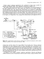
Figure 13.41: Waste generation cycle including billing (reproduced by
permission of MOBA Mobile Automation GmbH, Elz)
In Germany RFID systems are already in use in various cities, including Bremen,
Cologne and Dresden, and in numerous communities.
This document was created by an unregistered ChmMagic, please go to to register it. Thanks.
13.9 Sporting Events
In large-scale sporting events such as major marathons, the runners who start at the
back of the field are always at a disadvantage, because their times are calculated
from the moment the race is started. For many runners it takes several minutes
before they actually cross the starting line. In very large events with 10 000
participants or more, it might be 5 minutes before the last runners have crossed the
starting line. Without individual timing, the runners in the back rows are therefore at a
severe disadvantage.
To rectify this injustice, all runners carry a transponder with them. The system is
based upon the idea that each runner places his feet repeatedly on the ground and
thus comes very close to a ground antenna. In experimental events it was found that
using a ingenious arrangement of multiple antennas in an array and a chip in the shoe
over 1000 runners can be registered up to eight times in a minute with a start width of
just 4 m (ChampionChip, n.d.).
The transponder is based upon a glass transponder operating in the frequency range
135 kHz, embedded into a specially shaped (ABS) injection moulded housing (Figure
13.42). To get the transponder as close as possible to the ground — and thus to the
antenna of the time measurement device — this is attached to the runner's shoe using
the shoelaces (Figure 13.43).
Figure 13.42: The transponder consists of a glass transponder, which is
injected into a plastic housing that is shaped according to its function. The
diagram shows the partially cut away plastic housing
This document was created by an unregistered ChmMagic, please go to to register it. Thanks.
Figure 13.43: The ChampionChip transponder is fastened to the runner's shoe
with the shoelace (reproduced by permission of ChampionChip BV,
NL-Nijmegen)
The reader antennas are cast into thin mats and can thus be placed on the ground
and still be protected from all environmental influences (Figure 13.44). The
dimensions of a single mat are 2.10m × 1.00 m. At a normal running speed a net time
resolution of ±1 s is possible, derived from the time the runner remains within the read
range of a mat. The accuracy for cyclists improves to ±0.2 seconds. The measured
time is immediately displayed on a screen, so that the reader can read his current
intermediate time or final time as he passes a control station.
Figure 13.44: A control station consists of a main system and a reserve
system. The systems are made up of arrays of antennas in mats
The runner can make a one-off purchase of the transponder for 38 DM and then use it
wherever compatible timing systems are used.
The performance of a transponder based timing system has been demonstrated at
the following events: Rotterdam Marathon (10000 participants), Shell Hanseatic
Marathon, Hamburg (11 500 participants) and the Berlin Marathon (13 500
participants) (Champion-chip). See Figure 13.45.
This document was created by an unregistered ChmMagic, please go to to register it. Thanks.
Figure 13.45: Runners passing the control station at the end of the 101st
Boston Marathon. In the foreground we can see the mats containing the
readers. The times can be displayed on a screen immediately (reproduced by
permission of ChampionChip, NL-Nijmegen)
This document was created by an unregistered ChmMagic, please go to to register it. Thanks.
13.10 Industrial Automation
13.10.1 Tool identification
As well as its metal cutting tool industry, Germany's woodworking industry also plays a
dominant role in the world market. The modern woodworking and furniture
manufacturing industry is dominated by CNC technology because this enables
manufacturers to manufacture at a low cost and remain competitive.
CNC machines equipped with tool holders and automatic tool changers fulfil tasks that
are increasingly associated with small batch production. This increases the proportion
of manufacturing costs incurred by retooling and tool-change times.
Another consideration is the fact that a CNC woodworking machine differs from a
metalworking machine because of its higher rotation and path speeds. Rotation
speeds from 1000 min
-1
to more than 20 000 min
-1
(!) are attained in wood and
plastic processing. The risk of accidents for man and machine is therefore very high
during the tool-change operation; for example, hazards may be caused by the wrong
fitting of the CNC machine's chain magazine (Leitz, n.d.; Töppel, 1996).
This potential hazard can be eliminated by fitting a transponder in the taper shaft or in
the retention bolts of the toolholder (Figures 13.46 and 13.47). All relevant tool data are
preprogrammed into the transponder by the tool manufacturer. The machine operator
fits the transponder tools into the CNC machine's toolholder in any order. Then the
CNC machine initiates an automatic read sequence of all tools in the toolholder, during
which the tools are first ordered into toolholder positions and then all geometric and
technical data for the tools is transmitted correctly to the tool management system of
the CNC control unit (Figure 13.48). There is no manual data entry, which eliminates
the possibility of human error (leitz, n.d.). The danger of accidents due to excessive
speeds, the selection of the wrong rotation direction or the incorrect positioning of the
tool in relation to the workpiece is thus eliminated.
Figure 13.46: CNC milling tool with transponder in the retention bolts
(reproduced by permission of Leitz GmbH & Co., Oberkochen)
This document was created by an unregistered ChmMagic, please go to to register it. Thanks.
Figure 13.47: Various woodworking tools with transponder data carrier in the
taper shaft (reproduced by permission of EUCHNER & Co.,
Leinfelden-Echterdingen)
Figure 13.48: Representation of the tool cycle when using transponder coded
CNC tools
Inductively coupled transponders operating in the frequency range <135 kHz are
used. The transponder coil is mounted on a ferrite core to shield it from the metal
surface (see also Sections 4.1.12.3 and 2.2). The transponder must have a minimum
of 256 bytes of memory, which is written with an ASCII string containing the required
tool data. An example of a data record is illustrated in Table 13.4 (from Leitz, n.d.).
This document was created by an unregistered ChmMagic, please go to to register it. Thanks.
Table 13.4: Example of a data record for a tool transponder
CustomerFurniture Production Plant XY
LEITZ ID no.130004711 D25x60
Manufacturing ref.Y21
Place of manufactureUHE
Rotation direction3
Max. rotation speed24 000
Min. rotation speed18 000
Ideal rotation speed20 000
Radius correction25 011
Longitudinal correction145 893
Greatest radius25 500
Greatest length145 893
Maximum travel3000
Current travel875
Tool number14
Tool type1
Number of sharpenings2
Angle of clearance20
Cutting rake15
Free textFinishing cutter HM Z = 3
Modern transponder coded CNC tools can be incorporated into a cost saving
production and service cycle. The service cycle is incorporated, smoothly and simply,
into the production cycle as follows.
The worn tool is first examined and measured in detail to determine its condition. The
tool is then serviced, sharpened and balanced on the basis of this data. After every
maintenance sequence the tool length and radius is updated and written to the
transponder, so that correctly dimensioned workpieces are produced by both new and
sharpened tools without intervention by the operator.
13.10.2 Industrial production
Production processes underwent a process of continuous rationalisation during the
development of industrial mass production. This soon led to production line assembly
('conveyor belt production'), with the same stage of production being performed at a
certain position on the assembly line time after time. For the present, a production
process of this type is only able to produce objects that are identical in function and
appearance. However, the days are numbered for machines that produce large
quantities of a single product with no variants.
If different variants of a product are to be produced at the same time on an assembly
line in an automated procedure, the object must be identified and its status clearly
recognised at every work station, so that the correct processes can be performed.
This document was created by an unregistered ChmMagic, please go to to register it. Thanks.