emerging wireless multimedia services and technologies phần 5 docx
Bạn đang xem bản rút gọn của tài liệu. Xem và tải ngay bản đầy đủ của tài liệu tại đây (570.09 KB, 46 trang )
Equation (5.32) can be simplified to yield
B
1;W
i
;q
¼
4B
i
ð1 À p
b
Þð1 À p
ab
Þ
W
i
qðq þ 1Þ
:
ð5:34Þ
Using the above equation and Equation (5.33) we have
B
i;j;k
¼
ðq À kÞðW
i
À jÞ4ð1 À pÞð1 À 2pÞp
i
ð1 À p
b
Þð1 À p
ab
Þ
h
W
0
ð1 Àð2pÞ
mþ1
Þð1 À pÞþð1 À 2pÞð1 À p
mþ1
Þ
i
W
i
qðq þ 1Þ
:
ð5:35Þ
Now making j and k equal to 0 in Equation (5.35) we get
B
i;0;0
¼
4ð1 À pÞð1 À 2pÞp
i
ð1 À p
b
Þð1 À p
ab
Þ
h
W
0
ð1 Àð2pÞ
mþ1
Þð1 À pÞþð1 À 2pÞð1 À p
mþ1
Þ
i
ðq þ 1Þ
:
ð5:36Þ
From the above equation it is easier to determine the probability of transmission, , in an arbitrary slot:
¼
X
m
i¼0
B
i;0;0
¼
4ð1 À 2pÞð1 À p
b
Þð1 À p
ab
Þð1 À p
mþ1
Þ
h
W
0
ð1 Àð2pÞ
mþ1
Þð1 À pÞþð1 À 2pÞð1 À p
mþ1
Þ
i
ðq þ 1Þ
:
ð5:37Þ
The above equation considers the decrementing lab as the difference between the current node’s AIFS
and the highest priority’s AIFS. But if we have a system with more than one priority, we have to include
intermediate priorities and their access probabilities before the considered node can decrement its
backoff value. For the sake of simplicity we assume the 1 À p
ab
is valid even if there are multiple
priorities with different AIFS and hence the above equation is valid.
Example 1
Consider that there are only two ACs in the system. Let their CW
min
, CW
max
and TXOP be equal. Let
AC1 have AIFS¼DIFS and the second AC2 have AIFS¼PIFS. From Equation (5.37), we get a following
simple relation on the access probabilities:
2
¼
1 À p
ab
2
1
:
ð5:38Þ
This implies that the access probability is lowered by half and if the number of stations of priority 1 is
very large then it further lowers the probability of priority 2’s access.
Let us now introduce the four access categories as in EDCA and determine all the associated
probabilities. The probability that the tagged station of priority (AC ¼ lð¼ 0; 1; 2; 3Þ) transmits at slot t
is given by
l
t
¼
P
m
i¼0
B
l
i;0;0
: if t > AIFS½l
0 : if t AIFS½l:
&
ð5:39Þ
Equation (5.39) states that after the medium becomes idle following the busy period, the transmission
probability of the node with priority l is 0 if AIFS½l is not completed.
If the number of stations of each class is N
l
ðl ¼ 0; ; 3Þ, then the probability of the channel is busy
at an offset slot t is given by
p
l
b;t
¼ 1 Àð1 À
l
t
Þ
N
l
À1
Y
h6¼l
ð1 À
h
t
Þ
N
h
:
ð5:40Þ
164 Multimedia Wireless Local Area Networks
Equation (5.40) accounts for the fact that the tagged station of class l sees the channel is busy only when
at least one of the other station transmits. After calculating the busy probability, we go on to find the
probability of successful transmission of priority l in an offset slot t. This is given by
p
l
succ;t
¼
N
l
1
l
t
ð1 À
l
t
Þ
N
l
À1
Y
h 6¼ l
ð1 À
h
t
Þ
N
h
:
ð5:41Þ
Similarly we the probability that the offset slot t is idle is given by
p
idle;t
¼
Y
3
h¼0
ð1 À
h
t
Þ
N
h
:
ð5:42Þ
Now we can easily evaluate the probability of collision at offset slot t as
p
coll;t
¼ 1 À p
idle;t
À
X
3
h¼0
p
h
succ;t
:
ð5:43Þ
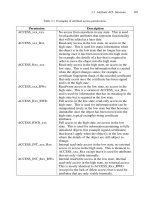
Based on the above three equations, it is easy to calculate the throughput of the EDCA system. The
transmission cycle under the EDCA of the IEEE 802.11e MAC consists of the following phases, which
are executed repetitively: the AIFS½AC=SIFS deferral phase, the backoff/contention phase if necessary,
the data/fragment transmission phase, the SIFS deferral phase, and the ACK transmission phase. The
related characteristics for the IEEE 802.11a PHY are listed in Table 5.3. As indicated in [19,21], we
assume that each transmission, whether successful or not, is a renewal process. Thus it is sufficient to
calculate the throughput of the EDCA protocol during a single renewal interval between two successive
transmissions. We extend the same philosophy for the EDCA bursting. The throughput of the protocol
without bursting is given by Equation (5.44):
S
h
¼
E½Time for successful transmission in an interval
E½Length between two consecutive transmissions
¼
P
t
P
3
h¼0
h
t
p
h
succ;t
L
h
P
t
h
t
ð
P
3
h¼0
T
h
s
p
h
succ;t
þ T
c
p
coll;t
þ aSlotTime Á p
idle;t
Þ
:
ð5:44Þ
T
s
is the average time the channel is captured with successful transmission and T
c
is the average time the
channel is captured by unsuccessful transmission. The values of T
s
and T
c
are given by
T
s
¼ AIFS½ACþ þ T
m
data
ðLÞþaSIFSTime þ T
m
ack
þ ð5:45Þ
T
c
¼ AIFS½ACþT
m
data
ðLÞþaSIFSTime þ T
m
ack
: ð5:46Þ
The in the above equation represents the propagation delay. Also the T
c
is equal to the frame
transmission time excluding the propagation delay because of Network Allocation Vector (NAV) set by
the transmitting QSTA.
5.A.4 Throughput Analysis for EDCA Bursting
In the case of EDCA bursting, we need to know the maximum number of frames that can be transmitted
during the EDCA TXOP limit. Let T
l
EDCA
txop
represent the TXOP limit for this AC. Therefore the
maximum number of frames of priority l, N
l
max
, that can be transmitted by a specific queue when it gets
to access the channel T
l
EDCA
txop
is given by Equation (5.47):
N
max
¼
T
l
EDCA
txop
ðAIFS½lÀaSIFSTimeÞþ2 ÁðaSIFSTime þ ÞþT
m
data
ðLÞþT
m
ack
ðLÞ
$%
: ð5:47Þ
Appendix 165
In Equation (5.47) , the first term on the denominator comes from the fact that we have used aSIFSTime
as the time between the transmission of the data frame as well as acknowledgment frame. In reality the
first frame has deference given by AIFS½l. For the throughput analysis, as we considered for single
frame transmission, we consider the period between two transmissions. This assumption is valid as each
WSTA that contends for the channel normally and if it gets the channel time, it transmits multiple
frames instead of one. Once the WSTA wins the contention, the number of frames it transmits is upper
bounded by Equation (5.47) . So on an average, the number of successful frame transmissions during
and EDCA TXOP limit is given by:
N
0
max
¼
T
EDCA txop
½l
½ðAIFS½lÀaSIFSTimeÞþ2 ÁðaSIFSTime þ ÞþT
m
data
ðLÞþT
m
ack
ðLÞN
Transmissions
" #
:
ð5:48Þ
The throughput is the same as discussed in the previous subsection.
References
[1] ETSI, HiperLAN Functional Specification, ETSI Draft Standard, July 1995.
[2] G. Anastasi, L. Lenzini and E. Mingozzi, Stability and Performance Analysis of HiperLAN, IEEE JSAC, 30(90),
1787–1798, 2000.
[3] K. Pahlavan and P. Krishnamurthy, Principles of Wireless Networks, Prentice Hall, 2002.
[4] B. Walke, N. Esseling, J. Habetha, A. Hettich, A. Kadelka, S. Mangold, J. Peetz, and U. Vornefeld, IP over
Wireless Mobile ATM – Guaranteed Wireless QoS by HiperLAN/2, in Proceedings of the IEEE, 89, pp. 21–40,
January 2001.
[5] IEEE Std 802.11-1999, Part 11: Wireless LAN Medium Access Control (MAC) and Physical Layer (PHY)
specifications, Reference number ISO/IEC 8802-11:1999(E), IEEE Std 802.11, 1999.
[6] IEEE Std 802.11a, Wireless LAN Medium Access Control (MAC) and Physical Layer (PHY) specifications:
Higher-speed Physical Layer Extension in the 5 GHz Band, Supplement to Part 11, IEEE Std 802.11a-1999,
1999.
[7] IEEE 802.11e/D7.0, Draft Supplement to Part 11: Wireless Medium Access Control (MAC) and physical layer
(PHY) specifications: Medium Access Control (MAC) Enhancements for Quality of Service (QoS), June 2003.
[8] IEEE 802.1d-1998, Part 3: Media Access Control (MAC) bridges, ANSI/IEEE Std. 802.1D, 1998.
[9] Sunghyun Choi, Javier del Prado, Sai Shankar N and Stefan Mangold, IEEE 802.11e Contention-Based Channel
Access (EDCA) Performance Evaluation, in Proc. IEEE ICC’03, Anchorage, Alaska, USA, May 2003
[10] Javier del Prado and Sai Shankar et al. Mandatory TSPEC Parameters and Reference Design of a Simple
Scheduler, IEEE 802.11-02/705r0, November 2002.
[11] C.T. Chou, Sai Shankar N and K.G. Shin, Distributed control of airtime usage in multi-rate wireless LANs,
submitted to IEEE Transactions on Networking.
[12] Maarten Hoeben and Menzo Wentink, Enhanced D-QoS through Virtual DCF, IEEE 802.11-00/351, October
2000.
[13] Stefan Mangold, Sunghyun Choi, Peter May, Ole Klein, Guido Hiertz and Lothar Stibor, IEEE 802.11e Wireless
LAN for Quality of Service, in Proc. European Wireless ’02, Florence, Italy, February 2002.
[14] Sunghyun Choi, Javier del Prado, Atul Garg, Maarten Hoeben, Stefan Mangold, Sai Shankar and Menzo
Wentink, Multiple Frame Exchanges during EDCA TXOP, IEEE 802.11-01/566r3, January 2002.
[15] J. G. Proakis, Digital Communications, 3rd ed, McGraw Hill, New York, NY, 1995.
[16] M. B. Pursley and D. J. Taipale, Error probabilities for spread spectrum packet radio with convolutional codes
and viterbi decoding, IEEE Trans. Commun., 35(1), pp. 1–12, Jan. 1987.
[17] D. Haccoun and G. Begin, High-rate punctured convolutional codes for Viterbi and sequential decoding, IEEE
Trans. Commun., 37(11), pp. 1113–1125, November 1989.
[18] F. Cali, M. Conti and E. Gregori, Dynamic Tuning of the IEEE 802.11 Protocol to achieve a theoretical
throughput limit, IEEE/ACM Trans. Netw., 8(6), December 2000.
[19] G. Bianchi, Performance Analysis of the IEEE 802.11 Distributed Coordination Function, IEEE Journal on
Selected Areas in Communications, 18(3), March 2000.
166 Multimedia Wireless Local Area Networks
[20] H. S. Chhaya and S. Gupta, Performance modeling of asynchronous data transfer methods of IEEE 802.11 MAC
protocol, Wireless Networks, 3, pp. 217–234, 1997.
[21] H. Wu et al., Performance of reliable transport protocol over IEEE 802.11 Wireless LAN: Analysis and
enhancement, Proc. IEEE INFOCOM’02, New York, June 2002.
[22] Daji Qiao and Sunghyun Choi, Goodput enhancement of IEEE 802.11a wireless LAN via link adaptation, in
Proc. IEEE ICC’01, Helsenki, Finland, June 2001.
[23] Daji Qiao, Sunghyun Choi, Amjad Soomro and Kang G. Shin, Energy-efficient PCF operation of IEEE 802.11a
wireless LAN, in Proc. IEEE INFOCOM’02, New York, June 2002.
[24] M. Zorzi, Ramesh R. Rao and L. B. Milstein, On the accuracy of a first-order Markov model for data
transmission on fading channels, in Proc. IEEE ICUPC’95, pp. 211–215, November 1995.
[25] J. I. Marcum, A Statistical theory of target detection by pulsed radar: mathematical appendix, IEEE Trans. Info.
Theory, pp. 59-267, Apr. 1960.
[26] M. Heusse, Franck Rousseau, Gilles Berger-Sabbatel and Andrzej Duda, Performance anomaly of IEEE
802.11b, in IEEE INFOCOM 2003, San Francisco, USA.
[27] Delprado, J. and Sai Shankar N., Impact of frame size, number of stations and mobility on the throughput
performance of IEEE 802.11e WLAN, in IEEE WCNC 2004, Atlanta, USA.
[28] Sunghyun Choi, Chiu Ngo, and Atul Garg, Comparative Overview on QoS Support via IEEE 802.11e and
HIPERLAN/2 WLANs, Philips Research USA Internal Document, June 2000.
[29] Sai Shankar N., Javier Delprado, and Patrick Wienert, Optimal packing of VoIP calls in an IEEE 802.11a/e
WLAN in the presence of QoS Constraints and Channel Errors, to appear in IEEE Globecom 2004, Dallas, USA.
[30] Chou, C. T., Sai Shankar N, and Shin K. G. Per-stream QoS in the IEEE 802.11e Wireless LAN: An integrated
airtime-based admission control and distributed airtime allocation, submitted to IEEE INFOCOM 2005, Miami,
USA.
References 167
6
Wireless Multimedia Personal Area
Networks: An Overview
Minal Mishra, Aniruddha Rangnekar and Krishna M. Sivalingam
6.1 Introduction
The era of computing has now shifted from traditional desktop and laptop computers to small, handheld
personal devices that have substantial computing, storage and communications capabilities. Such
devices include handheld computers, cellular phones, personal digital assistants and digital cameras.
It is necessary to interconnect these devices and also connect them to desktop and laptop systems in
order to fully utilize the capabilities of the devices. For instance, most of these devices have personal
information management (PIM) databases that need to be synchronized periodically. Such a network of
devices is defined as a Wireless Personal Area Network (WPAN). A WPAN is defined as a network of
wireless devices that are located within a short distance of each other, typically 3–10 meters. The IEEE
802.15 standards suite aims at providing wireless connectivity solutions for such networks without
having any significant impact on their form factor, weight, power requirements, cost, ease of use or other
traits [1]. In this chapter, we will explore the various network protocol standards that are part of the
IEEE 802.15 group. In particular, we describe IEEE 802.15.1 (Bluetooth
1
) offering 1–2 Mbps at
2.4 GHz, IEEE 802.15.3 (WiMedia) offering up to 55 Mbps at 2.4 GHz, IEEE 802.15.3a offering several
hundred Mbps using Ultra-wide-band transmissions, and IEEE 802.15.4, which is defined for low-bit
rate wireless sensor networks.
The IEEE 802.15 group adopted the existing Bluetooth
1
standard [2] as part of its initial efforts in
creating the 802.15.1 specifications. This standard uses 2.4 GHz RF transmissions to provide data rates
of up to 1 Mbps for distances of up to 10 m. However, this data rate is not adequate for several
multimedia and bulk data-transfer applications. The term ‘multimedia’ is used to indicate that the
information/data being transferred over the network may be composed of one or more of the following
media types: text, images, audio (stored and live) and video (stored and streaming). For instance,
transferring all the contents of a digital camera with a 128 MB flash card will require a significant
amount of time. Other high-bandwidth demanding applications include digital video transfer from a
camcorder, music transfer from a personal music device such as the Apple iPod
TM
. Therefore, the
802.15 group is examining newer technologies and protocols to support such applications.
Emerging Wireless Multimedia: Services and Technologies Edited by A. Salkintzis and N. Passas
# 2005 John Wiley & Sons, Ltd
There are two new types of Wireless Personal Area Networks (WPAN) that are being considered: the
first is for supporting low speed, long life-time and low cost sensor network at speeds of a few tens of
kbps and the other is for supporting the multimedia applications with higher data rates of the order of
several Mbps with better support for Quality of Service (QoS). Our focus, in this chapter, is on the
second type of WPAN dealing with multimedia communication. In an effort to take personal networking
to the next level, a consortium of technology firms has been established, called the WiMedia
Alliance[3]. The WiMedia Alliance develops and adopts standards-based specifications for connecting
wireless multimedia devices, including: application, transport, and control profiles; test suites; and a
certification program to accelerate wide-spread consumer adoption of ‘wire-free’ imaging and multi-
media solutions.
Even though the operations of the WPAN may resemble that of WLAN (Wireless Local Area
Networks), the interconnection of personal devices is different from that of computing devices. A
WLAN connectivity solution for a notebook computer associates the user of the device with the data
services available on, for instance, a corporate Ethernet-based intranet. A WPAN can be viewed as a
personal communications bubble around a person, which moves as the person moves around. Also, to
extend the WLAN as much as possible, a WLAN installation is often optimized for coverage. In contrast
to a WLAN, a WPAN trades coverage for power consumption.
The rest of this chapter is organized as follows. The following section gives a brief overview of the
multimedia data formats and application requirements. In Section 6.3, we present the Bluetooth
protocols as described in the IEEE 802.15.1 standard. In Section 6.4, we discuss issues related to
coexistence of Bluetooth networks with other unlicensed networks operating in the same frequency
region. The IEEE 802.15.3 protocol suite for multimedia networks is considered in Section 6.5. In
addition, we also describe ultra-wide-band (UWB) based networks that offer data rates of several
hundred Mbps. In order to complete the discussions of the entire IEEE 802.15 group of standards, we
also present the IEEE 802.15.4 standard for low-rate Wireless Personal Area Networks.
6.2 Multimedia Information Representation
In general, the term ‘multimedia traffic’ denotes a set of various traffic types with differing service
requirements. The classical set of multimedia traffic include audio, video (stored or streaming), data and
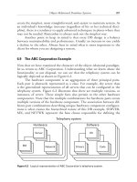
images [4,5]. The different types of media have been summarized in the Figure 6.1. Some applications
generate only one type of media, while others generate multiple media types. The representation and
compression of multimedia data has been a vast area of research. In this section, we present an overview
of multimedia information representation. We will consider an example scenario that consists of a
desktop computer, a laptop computer, and several digital peripheral devices such as digital camera,
digital camcorder, MP3 player, Personal Music Storage device (e.g. iPod
TM
), laser printer, photo printer,
fax machine, etc.
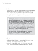
The applications involving multimedia information comprise blocks of digital data. For example, in
the case of textual information consisting of strings of characters entered at a keyboard, each character is
represented by a unique combination of fixed number of bits known as a codeword. There are three types
of text that are used to produce pages of documents: unformatted or plain text, formatted text and
hypertext. Formatted text refers to text rich documents that are produced by typical word processing
packages. Hypertext is a form of formatted text that uses hyperlinks to interconnect a related set of
documents, with HTML, SGML and XML serving as popular examples.
A display screen of any computing device can be considered to be made of a two dimensional matrix
of individual picture elements (pixels), where each pixel can have a range of colors associated with it.
The simplest way to represent a digitized image is using a set of pixels, where each pixel uses 8 bits of
data allowing 256 different colors per pixel. Thus, a 600 Â 300 picture will require approximately 175 kb
of storage. Compression techniques can be used to further reduce the image size. An alternate
representation is to describe each object in an image in terms of the object attributes. These include
170 Wireless Multimedia Personal Area Networks: An Overview
its shape, size (in terms of pixel positions of its border coordinates), color of the border, and shadow.
Hence the computer graphic can be represented in two different ways: a high level version (specifying
the attributes of the objects) and an actual pixel image of the graphic, also referred to as the bitmap
format. It is evident that the high level version is more compact and requires less memory. When the
graphic is transmitted to another host, the receiver should be aware of high-level commands to render
the image. Hence, bitmaps or compressed images are used more often.
The commonly used image formats are GIF (graphic interchange format), TIFF (tagged image file
format), JPEG (Joint Photographers Experts Group) and PNG (Portable Network Graphics). Com-
pressed data formats also exist for transferring fax images (from the main computer to the fax machine).
In order to understand the data requirements, let us consider a 2 Mega-Pixel (2 MP) digital camera,
where the size of each image typically varies from 1 Mb to 2 Mb, depending on the resolution set by the
user. A 256 Mb memory card can store approximately 200 photos. There is always a need to periodically
transfer these digital files to a central repository such as a PC or a laptop. This is often done using the
USB interface, which can provide data rates of up to 12 Mbps for USB 1.1 and up to 480 Mbps for USB
2.0. However, our intention is to use wireless networking for interconnecting such multimedia devices
and the computer. The Bluetooth
1
standard provides data rates of 1 Mbps which is inadequate
compared with the USB speeds. For instance, 128 Mb worth of multimedia files would take at least
18 minutes to transfer from a camera to PC. This is the reason for the development of the higher bit-rate
IEEE 802.15.3 wireless PAN standard.
For audio traffic, we are concerned with two types of data: (i) speech data used in inter-personal
applications including telephony and video-conferencing and (ii) high-quality music data. Audio signals
can be produced either naturally using a microphone or electronically using some form of synthesizer
[5]. The analog signals are then converted to digital signals for storage and transmission purposes. Let us
consider the data requirements for audio traffic. Audio is typically sampled at 44100 samples per second
(for each component of the stereo output) with 1 byte per second to result in a total of approximately
705 kbps. This can be compressed using various algorithms, with MP3 (from the Motion Picture Experts
Audio VideoImages
Formatted
Text
Computer
Generated
Digitized
documents
Unformatted
Text
Text
Speech General
Audio
Video
Clips
Movies,
Films
Media Types
Digital form
of representation
Text and Image Compression
Analog form of
representation
Analog-to-Digital
Conversion
Audio and video
compression
Integrated multimedia information
streams
Figure 6.1 Different types of media used in multimedia applications.
Multimedia Information Representation 171
Group) [6] being one of the most popular standards that can compress music to as around 112–118 kbps
for CD-quality audio. Thus, streaming audio between a single source-destination pair is possible even
with Bluetooth
1
. However, if there are several users in a WPAN, each having different audio streams in
parallel, then higher bandwidths are necessary.
However, to store a CD-quality 4–5 minute song requires approximately 32 Mb of disk space. Hence,
bulk transfer of audio files between a computer and a personal music device (such as the Apple iPod
TM
)
requires a large bandwidth for transmission. There are several different ways to compress this data
before transmission and decompress it at the receiver’s end. The available bandwidth for transmission
decides the type of audio/video compression technique to be used.
Real-time video streaming with regular monitor-sized picture frames is still one of the holy grails of
multimedia networking. Video has the highest bandwidth requirement. For instance, a movie with 30
frames per second (fps), with 800 Â 600 pixels per frame and 8 bits per pixel requires an uncompressed
bandwidth of 115 Mbps. There have been several compression standards for video storage. The
MPEG-1 standard used on Video-CDs requires bandwidth of approximately 1.5 Mbps for a
352 Â 288 pixel frame. The MPEG-2 standard used on DVDs today supports up to 720 Â 576 pixel-
frame with 25 fps for the PAL standard and 720 Â 480 pixel-frame with 30 fps for the NTSC standard.
The effective bandwidth required ranges from 4 Mbps to 15 Mbps. The MPEG-4 standard, approved in
1998, provides scalable quality, not only for high resolution, but also for lower resolution and lower
bandwidth applications. The bandwidth requirements of MPEG-4 are very flexible due to the versatility
of the coding algorithms and range from a few kbps to several Mbps. It is clear that higher bandwidth
WPANs such as IEEE 802.15.3 are necessary to handle video traffic. Other video standards such as
High-Definition Television (HDTV) can require bandwidths of around 80–100 Mbps, depending upon
the picture quality, compression standards, aspect ratios, etc.
In the following sections, we describe the various WPAN networking protocols and architectures.
6.3 Bluetooth
1
(IEEE 802.15.1)
Bluetooth
1
is a short-range radio technology that enabled wireless connectivity between mobile
devices. Its key features are robustness, low complexity, low power and low cost. The IEEE 802.15.1
standard is aimed at achieving global acceptance such that any Bluetooth
1
device, anywhere in the
world, can connect to other Bluetooth
1
devices in their proximity. A Bluetooth
1
WPAN supports both
synchronous communication channels for telephony-grade voice communication and asynchronous
communications channels for data communications. A Bluetooth
1
WPAN is created in an ad hoc
manner when devices desire to exchange data. The WPAN may cease to exist when the applications
involved have completed their tasks and no longer need to continue exchanging data.
The Bluetooth
1
radio works in the 2.4 GHz unlicensed ISM band. A fast frequency hop (1600 hops
per second) transceiver is used to combat interference and fading in this band. Bluetooth
1
belongs to
the contention-free, token-based multi-access networks. Bluetooth
1
connections are typically ad hoc,
which means that the network will be established for a current task and then dismantled after the data
transfer has been completed. The basic unit of a Bluetooth
1
system is a piconet, which consists of a
master node and up to seven active slave nodes within a radius of 10 meters. A piconet has a gross
capacity of 1 Mbps without considering the overhead introduced by the adopted protocols and polling
scheme. Several such basic units having overlapping areas may form a larger network called a
scatternet. A slave can be a part of a different piconet only in a time-multiplexing mode. This indicates
that, for any time instant, the node can only transmit or receive on the single piconet to which its clock is
synchronized and to be able to transmit in another piconet it should change its synchronization
parameters. Figure 6.2 illustrates this with an example. A device can be a master in only one piconet, but
it can be a slave in multiple piconets simultaneously. A device can assume the role of a master in one
piconet and a slave in other piconets. Each piconet is assigned a frequency-hopping channel based on
the address of the master of that piconet.
172 Wireless Multimedia Personal Area Networks: An Overview
6.3.1 The Bluetooth
1
Protocol Stack
The complete protocol stack contains a Bluetooth
1
core of certain Bluetooth
1
specific protocols:
Bluetooth
1
radio, baseband, link manager protocol (LMP), logical link control and adaptation protocol
(L2CAP) and service discovery protocol (SDP) as shown in Figure 6.3. In addition, non-Bluetooth
specific protocols can also be implemented on top of the Bluetooth
1
technology.
The bottom layer is the physical radio layer that deals with radio transmission and modulation. It
corresponds fairly well to the physical layer in the OSI and 802 models. The baseband layer is somewhat
analogous to the MAC (media access control) sublayer but also includes elements of the physical layer.
It deals with how the master controls the time slots and how these slots are grouped into frames. The
physical and the baseband layer together provides a transport service of packets on the physical links.
Next comes a layer of somewhat related protocols. The link manager handles the setup of physical
links between devices, including power management, authentication and quality of service. The logical
link control and adaptation protocol (often termed L2CAP) shields the higher layers from the details of
transmission. The main features supported by L2CAP are: protocol multiplexing and segmentation and
Master
Slave
c
ab
Figure 6.2 (a) Point-to-point connection between two devices; (b) point-to-multi-point connection between master
and three slaves and (c) scatternet that consists of three piconets.
Physical Radio
Baseband
Link Manager
Logical Link Control and Adaptation Protocol
LLC
Other
RFCOMM Telephony Service
Discovery
ControlAudio
Application/Profiles
Figure 6.3 Bluetooth
1
protocol stack.
Bluetooth
1
(IEEE 802.15.1) 173
reassembly. The latter feature is required because the baseband packet size is much smaller than the
usual size of packets used by higher-layer protocols. The SDP protocol is used to find the type of
services that are available in the network. Unlike the legacy wireless LANs, there is no system
administrator who can manually configure the client devices. In the following sections the lower layers
of the Bluetooth
1
protocol stack have been examined in detail.
6.3.2 Physical Layer Details
Bluetooth
1
radio modules use Gaussian Frequency Shift Keying (GFSK) for modulation. A binary
system is used where a ‘1’ is represented by a positive frequency deviation and a ‘0’ is represented by a
negative frequency deviation. The channel is defined by a pseudo-random hopping sequence hopping
through 79 RF (radio frequency) channels 1 MHz wide. There is also a 23 channel radio defined for
countries with special radio frequency regulations. The hopping sequence is determined by the
Bluetooth
1
device address (a 48 bit address compliant with IEEE 802 standard addressing scheme)
of the master and hence it is unique to the piconet. The phase or the numbering of the hopping sequence
is determined by the bluetooth clock of the piconet master. The numbering ranges from 0 to 2
27
À 1 and
is cyclic with a cycle length of 2
27
since the clock is implemented as a 28-bit counter. Therefore, all
devices using the same hopping sequence with the same phase form a piconet. With a fast hop rate, good
interference protection is achieved. The channel is divided into time slots (625 microseconds in length)
where each slot corresponds to particular RF hop frequency. The consecutive hops correspond to
different RF hop frequencies. The nominal hop rate is 1600 hops/s. The benefit of the hopping scheme is
evident when some other device is jamming the transmission of a packet. In this scenario, the packet is
resent on another frequency determined by the frequency scheme of the master [2].
Bluetooth
1
provides three different classes of power management. Class 1 devices, the highest power
devices operate at 100 milliwatt (mW) and have an operating range of up to 100 meters (m). Class 2
devices operate at 2.5 mW and have an operating range of up to 10 m. Class 3, the lowest power devices,
operate at 1 mW and have an operating range varying from 0.1 to 1 m. The three levels of operating
power is summarized in the Table 6.1.
A time division duplex (TDD) is used where the master and slave transmit alternately. The
transmission of the master shall start at the beginning of the even numbered slots and that of the
slave shall start in the odd numbered time slots only. Figure 6.4 depicts the transmission when a packet
covers a single slot.
In multi-slot packets, the frequency remains the same until the entire packet is sent and frequency is
derived from the Bluetooth
1
clock value in the first slot of the packet. While using multi-slot packets,
the data rate is higher because the header and the switching time are needed only once in each packet
[7]. Figure 6.5 shows how three and five slot packets are used at the same frequency throughout the
transmission of the packets.
6.3.3 Description of Bluetooth
1
Links and Packets
Bluetooth
1
offers two different types of services: a synchronous connection-oriented (SCO) link and an
asynchronous connectionless link (ACL). The first type is a point-to-point, symmetric connection
Table 6.1 Device classes based on power management
Type Power Power level Operating range
Class 1 Devices High 100 mW (20 dBm) Up to 100 meters (300 feet)
Class 2 Devices Medium 2.5 mW (4 dBm) Up to 10 meters (30 feet)
Class 3 Devices Low 1 mW (0 dBm) 0.1–1 (less than 3 feet)
174 Wireless Multimedia Personal Area Networks: An Overview
between a master and a specific slave. It is used to deliver time-bounded traffic, mainly voice. The SCO
link rate is maintained at 64 kbit/s and the SCO packets are not retransmitted. The SCO link typically
reserves a couple of consecutive slots, i.e. the master will transmit SCO packets at regular intervals and
the SCO slave will always respond with a SCO packet in the following slave-to-master slot. Therefore, a
SCO link can be considered as a circuit switched connection between the master and the slave.
The other physical link, ACL, is a connection in which the master can exchange packets with any
slave on a per-slot basis. It can be considered a packet switched connection between the Bluetooth
1
devices and can support the reliable delivery of data. To assure data integrity, a fast automatic repeat
request scheme is adopted. A slave is permitted to return an ACL packet in the slave-master slot if and
only if it has been addressed in the preceding master-to-slave slot. An ACL channel supports point-to–
multipoint transmissions from the master to the slaves.
Master
Slave
625 µs
f(k)
f(k+2)
f(k+1)
Figure 6.4 Single slot packets depicting time division duplexing. ðf ðkÞ represents frequency at time-slot k).
f(k) f(k+3) f(k+4) f(k+5) f(k+6)
f(k)
f(k)
f(k+5) f(k+6)
625 µs
f(k) f(k+1) f(k+2) f(k+3) f(k+4) f(k+5) f(k+6)
(a)
(b)
(c)
Figure 6.5 (a) Single-slot packets; (b) three-slot packet; (c) five-slot packet. Three-slot and fiv e-slot long packets reduce
overhead compared with one-slot packets. 220 s switching time after the packet is needed for changing the frequency.
Bluetooth
1
(IEEE 802.15.1) 175
The general packet format transmitted in one slot is illustrated in Figure 6.6. Each packet consist of
three entities: the access code, the header and the payload. The access code and the header are of fixed
size 72 and 54 bits respectively, but the payload can range from 0 to 2075 bits. The bit ordering when
defining packets and messages in the Baseband Specification, follows the Little Endian format, i.e. the
following rules apply.
The LSB is the first bit sent over the air.
In Figure 6.6, the LSB is shown on the left-hand side.
The access code is derived from the master device’s identity, which is unique for the channel. The access
code identifies all the packets exchanged on a piconet’s channel, i.e. all packets sent on a piconet’s
channel are preceded by the same channel access code (CAC). The access code is also used to
synchronize the communication and for paging and inquiry procedures. In such a situation, the access
code is considered as a signaling message and neither header nor payload is included. To indicate that it
is a signaling message only the first 68 bits of access code are sent. The packets can be classified into
sixteen different types, using the four TYPE bits in the header of the packets. The interpretation of the
TYPE code depends on the physical link type associated with the packet, i.e. whether the packet is using
SCO or an ACL link. Once that is done, it can be determined which type of SCO or ACL packet has
been received. Four control packets are common to all the link types. Hence, twelve different types of
packet can be defined for each of the links. Apart from the type, the header also contains a 3-bit active
member’s address, 1-bit sequence number (S), 1-bit (F) for flow control of packets on the ACL links and
a 1-bit acknowledge indication. To enhance the reliable delivery of the packets, forward error correction
(FEC) and cyclic redundancy check (CRC) algorithms may be used. The possible presence of FEC,
CRC and multi-slot transmission results in different payload lengths. As the SCO packets are never
retransmitted, the payload is never protected by a CRC. The presence or absence of FEC also provides
two types of ACL packets: DMx (medium speed data) or DHx (high speed data) respectively where x
corresponds to the slots occupied by the packets. All ACL packets have a CRC field to check the
payload integrity.
6.3.4 Link Manager
The Link Manager Protocol (LMP) provides means for setting up secure and power efficient links for
both data and voice. It has the ability to update the link properties to obtain optimum performance. The
Link Manager also terminates connections, either on higher layers request or because of various failures.
Apart from these services, the LMP also handles different low-power modes.
ACCESS
CODE
HEADER PAYLOAD
LSB 72 54 0−2075 MSB
Addr Type F S Checksum The 18 bit header is encoded with a
rate 1/3 FEC resulting in 54 bits
3 4 1 1 1 8
A
Figure 6.6 Standard packet format.
176 Wireless Multimedia Personal Area Networks: An Overview
Sniff mode. The duty cycle of the slave is reduced, the slave listens for transmissions only at sniff-
designated time slots. The master’s link manager issues a command to the slave to enter the sniff
mode.
Hold mode. A slave in this mode does not receive any synchronous packets and listens only to
determine if it should become active again. The master and slave agree upon the duration of the hold
interval, after which the slave comes out of the Hold mode. During Hold mode, the device is still
considered an active member of the piconet and it maintains its active member address.
Park mode. This mode provides the highest power savings, as the slave has to only stay synchronized
and not participate on the channel. It wakes up at regular intervals to listen to the channel in order to
re-synchronize with the rest of the piconet, and to check for page messages. The master may remove
the device from the list of active members and may assign the active member address to another
device.
The services to upper layers in the complete protocol are provided by the Bluetooth
1
Logical Link
Control and Adaptation Protocol (L2CAP), which can be thought to work in parallel with LMP. L2CAP
must support protocol multiplexing because the Baseband protocol does not support any ‘type’ field
identifying the higher layer protocol being multiplexed above it. L2CAP must be able to distinguish
between upper layer protocols such as the Service Discovery Protocol, RFCOMM and Telephony
Control. The other important functionality supported by L2CAP is segmentation and reassembly of
packets larger than those supported by the baseband. If the upper layers were to export a maximum
transmission unit (MTU) associated with the largest baseband payload, then it would lead to an
inefficient use of bandwidth for higher layer protocols (as they are designed to use larger packets).
L2CAP provides both a Connection-Oriented and a Connectionless service. For the Connectionless
L2CAP channel, no Quality of Service (QoS) is defined and data are sent to the members of the group in
a best effort manner. The Connectionless L2CAP channel is unreliable, i.e. there is no guarantee that
each member of the group receives the L2CAP packets correctly. For the Connection-Oriented channel,
quality of service is defined and the reliability of the underlying Baseband layer is used to provide
reliability. For example, delay sensitive traffic would be transmitted over an ACL link between the two
communicating devices. Between any two Bluetooth
1
devices there is at most one ACL link. Therefore,
the traffic flows generated by each application on the same device compete for resources over the ACL
link. These traffic flows, however, may have different QoS requirements in terms of bandwidth and
delay. Hence, when there is contention for resources, the QoS functions enable service differentiation.
Service differentiation improves the ability to provide a ‘better’ service for one traffic flow at the
expense of the service offered to another traffic flow. Service differentiation is only applicable when
there is a mix of traffic. The service level is specified by means of QoS parameters such as bandwidth
and delay. In many cases there is a trade-off between QoS parameters, e.g. higher bandwidth provides
lower delay. It should be noted that service differentiation does not improve the capacity of the system.
It only gives control over the limited amount of resources that satisfy the needs of the different traffic
flows [8].
6.3.5 Service Discovery and Connection Establishment
The channel in the piconet is characterized entirely by the master of the piconet. The channel access
code and frequency hopping sequence is determined by the master’s Bluetooth
1
device address. The
master is defined as the device that initiates communication to one or more slave units. The names
master and slave refer only to the protocol on the channel and not the devices. Therefore, any device can
be a master or a slave in the piconet.
There are two major states that a bluetooth device can be in: Standby and Connection. In addition
there are seven sub-states: page, page scan, inquiry, inquiry scan, master response, slave response,
inquiry response. The sub-states are interim states that are used to add new slaves to the piconet. Internal
signals from the link controller are used to move from one state to another.
Bluetooth
1
(IEEE 802.15.1) 177
In order to set up a connection, a device must detect which other devices are in range. This is the goal
of the inquiry procedure. The inquiry procedure must overcome the initial frequency discrepancy
between the devices. Therefore, inquiry uses only 32 of the 79 hop frequency. A device in inquiry state
broadcasts ID packets, containing the 68-bit inquiry access code, on the 32 frequencies of the inquiry
hopping sequence. The inquiry hopping sequence is derived from the General Inquiry Access Code
(GIAC) that is common for all devices and hence is the same for all devices. A device wishing to be
found by inquiring units periodically enters inquiry scan sub-state. The device listens at a single
frequency of the inquiry hopping sequence for a period determined by the inquiry scan window. Upon
reception of an ID packet, a device in an inquiry scan sub-state will leave the inquiry scan sub-state for a
random backoff time, this is done to reduce the probability that multiple devices would response to the
same ID packet, thus colliding. After the random backoff, the device enters the inquiry response period
to listen for a second ID packet. Upon reception of this, the device responds with a packet containing its
device information, i.e. its device address and its current clock.
The connection establishment is handled by the page process, which requires the knowledge of the
device addres s with which the connection is to be established. The page hopping sequence consist of
32 frequencies, derived from the device address which is being paged. Furthermore, the device being
paged must be in the page scan sub-state, i.e. listening for page messages. When a unit in the page
scan mode receives an ID packet containing its own device access code (DAC), it acknowledges the
page message with a n ID packet and enters the slave response state. After receiving the ACK from
the paged device, the paging device enters th e master response sub-state and s ends a frequency hop
selection (FHS) packet containing its native clock, which will be the piconet clock and the active
member address (AMADDR) that the paged device shall use. The paged device acknowledges the
FHS packet and switches to the hopping sequence of the master. The two units are now connected
and they switch to connection state. Figure 6.7 presents the various state transitions during the
inquiry and paging process.
Standby
Standby
Standby
INQ INQ Scan
INQ Resp
Random Backoff
Start
Random Backoff
End
ID (GIAC)
ID (GIAC)
FHS (GIAC)
Standby
Standby
Standby
Standby
ID DAC
FHS DAC
POLL
NULL
Slave
Response
Master
Page Scan
Page
Response
Connection Connection
Scanning Device
Paging Device
Inquiring Device Scanning Device
Figure 6.7 State transitions during the inquiry and paging processes.
178 Wireless Multimedia Personal Area Networks: An Overview
6.3.6 Bluetooth
1
Security
The Bluetooth
1
specification includes security features at the link level. The three basic services
defined by the specification are the following.
(1) Authentication. This service aims at providing identity verification of the communicating
Bluetooth
1
devices. It addresses the question ‘Do I know with whom I am communicating?’. If
the device is unable to authenticate itself, then the connection is aborted.
(2) Confidentiality. Confidentiality, or privacy, is yet another security goal of Bluetooth
1
. The
information compromise caused by passive attacks is prevented by encrypting the data being
transmitted.
(3) Authorization. This service aims at achieving control over the available resources, thus preventing
devices that do not have access permissions from misusing network resources.
These services are based on a secret link key that is shared by two or more devices. To generate this key
a pairing procedure is used when the devices are communicating for the first time. For Bluetooth
1
devices to communicate, an initialization process uses a Personal Identification Number (PIN), which
may be entered by the user or can be stored in the non-volatile memory of the device. The link key is a
128-bit random number generated by using the PIN code, Bluetooth
1
Device address, and a 128-bit
random number generated by the other device as inputs. The link key forms a base for all security
transactions between the communicating devices. It is used in the authentication routine and also as one
of the parameters in deriving the encryption key. The Bluetooth
1
authentication scheme uses a
challenge-response protocol to determine whether the other party knows the secret key. The scheme is
illustrated in Figure 6.8. To authenticate, the verifier first challenges the claimant with a 128-bit random
number. The verifier, simultaneously, computes the authentication response by using the Bluetooth
1
device address, link key and random challenge as the inputs. The claimant returns the computed res-
ponse, SRES, to the verifier. The verifier then matches the response from the claimant with that compu-
ted by the verifier. Depending on the application, there can be either one-way or two-way authentication.
The Bluetooth
1
encryption scheme encrypts the payloads of the packets. When the link manager
activates encryption, the encryption key is generated and it is automatically changed every time the
Bluetooth
1
device enters encryption mode. The encryption key size may vary from 8 to 128 bits and is
negotiated between the communicating devices. The Bluetooth
1
encryption procedure is based on
stream cipher algorithm. A key stream output is exclusive-OR-ed with the payload bits and sent to the
receiving device, which then decrypts the payload. The Bluetooth
1
security architecture, though
relatively secure, is not without weaknesses. References [9, 10–12] have identified flaws in Bluetooth
1
security protocol architecture.
E1
=?
E1
Verifier (Unit A) Claimant (Unit B)
Rand A
SRES’
SRES
BD_AddrB
RandA
Link Key
RandA
BD_AddrB
Link Key
Figure 6.8 Challenge–Response mechanism for Bluetooth authentication scheme [9].
Bluetooth
1
(IEEE 802.15.1) 179
6.3.7 Application Areas
The ad hoc method of untethered communication makes Bluetooth
1
a very attractive technology and
can result in increased efficiency and reduced costs. The efficiencies and cost savings can lure both the
home user and the enterprise business user. Many different user scenarios can be imagined for
Bluetooth
1
wireless networks as outlined below.
Cable replacement. Today, most of the devices are connected to the computer via wires (e.g.,
keyboard, mouse, joystick, headset, speakers, printers, scanners, faxes, etc.). There are several
disadvantages associated with this, as each device uses a different type of cable, has different sockets
for it and may hinder smooth passage. The freedom of these devices can be increased by connecting
them wirelessly to the CPU.
File sharing. Imagine several people coming together, discussing issues and exchanging data. For
example, in meetings and conferences you can transfer selected documents instantly with selected
participants, and exchange electronic business cards automatically, without any wired connections.
Wireless synchronization. Bluetooth
1
provides automatic synchronization with other Bluetooth
1
enabled devices. For instance, as soon as you enter your office the address list and calendar in your
notebook will automatically be updated to agree with the one in your desktop, or vice versa.
Bridging of networks. Bluetooth
1
is supported by a variety of devices and applications. Some of
these devices include mobile phones, PDAs, laptops, desktops and fixed telephones. Bridging of
networks is possible, when these devices and technologies join together to use each others
capabilities. For example, a Bluetooth
1
-compatible mobile phone can act as a wireless modem
for laptops. Using Bluetooth
1
, the laptop interfaces with the cell phone, which in turn connects to a
network, thus giving the laptop a full range of networking capabilities without the need of an
electrical interface for the laptop-to-mobile phone connection.
Miscellaneous. There are several other potential applications for the Bluetooth
1
enabled devices. For
example, composing emails on the portable PC while on an airplane. As soon as the plane lands and
switches on the mobile phone, all messages are immediately sent. Upon arriving home, the door
automatically unlocks, the entry way lights come on, and the heat is adjusted to pre-set preferences.
When comparing Bluetooth
1
with the wireless LAN technologies, we have to realize that one of the
goals of Bluetooth
1
was to provide local wireless access at low costs. The WLAN technologies have
been designed for higher bandwidth and larger range and are, thus, much more expensive.
6.4 Coexistence with Wireless LANs (IEEE 802.15.2)
The global availability of the 2.4 GHz industrial, scientific, medical (ISM) unlicensed band, is the reason
for its strong growth. Fuelling this growth are the two emerging wireless technologies: wireless personal
area networks (WPAN) and wireless local area networks (WLAN). Bluetooth
1
, as the frontrunner of
personal area networking is predicted to flood the markets by the end of this decade. Designed principally
for cable replacement applications, Bluetooth
1
has been explained in significant detail in Section 3.
The WLAN has several technologies combating for dominance; but looking at the current market
trends, it is apparent that Wi-Fi (IEEE 802.11b) has been the most successful of them all. With WLANs,
applications such as Internet access, email and file sharing can be done within a building, supported by
the technology. Wi-Fi offers speed upto 11 Mbps and a range of up to 100 m. The other WLAN
technologies include the 802.11a and 802.11g standard. The 802.11a was developed at the same time as
802.11b but, due its higher costs, 802.11a fits predominately in the business market. 802.11a supports
bandwidth up to 54 Mbps and signals in a regulated 5 GHz range. Compared with 802.11b, this higher
frequency limits the range of 802.11a. The higher frequency also means that 802.11a signals have more
difficulty penetrating walls and other obstructions. In 2002, a new standard called 802.11g began to
appear on the scene. 802.11g attempts to combine the best of both 802.11a and 802.11b. 802.11g
180 Wireless Multimedia Personal Area Networks: An Overview
supports bandwidth up to 54 Mbps, and it uses the 2.4 GHz frequency for greater range. 802.11g is
backward compatible with 802.11b, meaning that 802.11g access points will work with 802.11b
wireless network adapters and vice versa.
The wireless local area networking and the wireless personal area networking are not competing
technologies; they complement each other. There are many devices where different radio technologies
can be built into the same platform (e.g., Bluetooth
1
in a cellular phone), collocation of Wi-Fi and
Bluetooth
1
is of special significance because both occupy the 2.4 GHz frequency band. This sharing of
spectrum among various wireless devices that can operate in the same environment may lead to severe
interference and result in performance degradation. Owing to the tremendous popularity of Wi-Fi and
Bluetooth
1
enabled devices the interference problem would spiral out of proportions. To prevent this,
there have been a number of industry led activities focused on coexistence in the 2.4 GHz band. One
such effort was the formation of the IEEE 802.15.2 Coexistence Task Group [13]. It was formed to
evaluate the performance of Bluetooth
1
devices interfering with WLAN devices and to develop a model
for coexistence that will consist of a set of recommended practices and possibly modifications to the
Bluetooth
1
and the IEEE 802.11 [14] standard specifications that allow proper operation of these
protocols in a cooperating way. The Bluetooth
1
SIG (Special Interest Group) has also created a
Coexistence Working Group, in order to achieve the same goals as the 802.15.2 Task Group.
6.4.1 Overview of 802.11 Standard
The IEEE 802.11 [14] standard defines both physical (PHY) and medium access control (MAC) layer
protocols for WLANs. The standard defines three different PHY specifications: direct sequence spread
spectrum (DSSS), frequency hopping spread spectrum (FHSS) and infrared (IR). Our focus would be on
the 802.11b standard (also called Wi-Fi), as it works in the same frequency band as Bluetooth
1
. Data
rates up to 11 Mbps can be achieved using techniques combining quadrature phase shift keying and
complementary code keying (CCK).
The MAC layer specifications coordinate the communication between stations and control the
behavior of users who want access to the network. The MAC specifications are independent of all
PHY layer implementations and data rates. The Distributed Coordination function (DCF) is the basic
access mechanism of IEEE 802.11. It uses a Carrier Sense Multiple Access with Collision Avoidance
(CSMA/CA) algorithm to mediate the access to the shared medium. Prior to sending a data frame, the
station senses the medium. If the medium is found to be idle for at least DIFS (DCF interframe space)
period of time, the frame is transmitted. If not, a backoff time is chosen randomly in the interval [0,
CW], where CW is the Contention Window. After the medium is detected idle for at least DIFS, the
backoff timer is decremented by one for each time slot the medium remains idle. If the medium becomes
‘busy’ during the backoff process, the backoff timer is paused. It is restarted once again after the
medium is sensed idle for a DIFS period. When the backoff timer reaches zero, the frame is transmitted.
Figure 6.9 depicts the basic access procedure of the 802.11 MAC. A virtual carrier sense mechanism is
also incorporated at the MAC layer. It uses the request-to-send (RTS) and clear-to-send (CTS) message
exchange to make predictions of future traffic on the medium and updates the network allocation vector
(NAV) available in all stations that can overhear the transmissions. Communication is established when
one of the stations sends an RTS frame and the receiving station sends the CTS frame that echoes the
sender’s address. If the CTS frame is not received by the sender then it is assumed that a collision has
occurred and the process is repeated. Upon successful reception of the data frame, the destination
returns an ACK frame. The absence of ACK frame indicates a collision has taken place. The contention
window is doubled, a new backoff time is then chosen, and the backoff procedure starts over. After a
successful transmission, the contention window is reset to CW
min
.
6.4.2 802.11b and Bluetooth
1
Interference Basics
Both Bluetooth
1
and Wi-Fi share the same 2.4 GHz band, which extends from 2.402 to 2.483 GHz. The
ISM band under the regulations of Federal Communications Commission (FCC) is free of tariffs, but
Coexistence with Wireless LANs (IEEE 802.15.2) 181
must follow some rules related to total radiated power and the use of spread spectrum modulation
schemes. These constraints are imposed to enable multiple systems to coexist in time and space. A
system can use one of the two spread spectrum (SS) techniques to transmit in this band. The first is the
Frequency Hopping Spread Spectrum (FHSS), where a device can transmit at high power in a relatively
narrow band but for a limited time. The second is the Direct Sequence Spread Spectrum (DSSS), where
a device occupies a wider band with relatively low energy in a given segment of the band and,
importantly, it does not hop frequencies [15].
As outlined in the preceding sections, Bluetooth
1
selected FHSS, using 1 MHz width and a hop rate
of 1600 times/s (i.e. 625 microseconds in every frequency channel) and Wi-Fi picked DSSS, using
22 MHz of bandwidth to transmit data at speeds of up to 11 Mbps. An IEEE 802.11b system can use any
of the eleven 22 MHz wide sub-channels across the acceptable 83.5 MHz of the 2.4 GHz frequency
band, which obviously results in overlapping channels. A maximum of three Wi-Fi networks can coexist
without interfering with one another, since only three of the 22 MHz channels can fit within the
allocated bandwidth [14].
A wireless communication system consist of at least two nodes, one transmitting the data and the
other receiving it. Successful operation of the system depends upon whether the receiver is able to
distinctly identify the desired signal. Further, this depends upon the ratio of the desired signal and the
total noise at the receiver’s antenna. This ratio is commonly referred to as the signal-to-noise ratio
(SNR). The main characteristic of the system is defined as the minimum SNR at which the receiver can
successfully decode the desired signal. A lower value of SNR increases the probability of an undesired
signal corrupting the data packets and forcing retransmission. Noise at the receiver’s antenna can be
classified into two categories: in-band and out-of-band noise. The in-band noise, which is the undesired
energy in frequencies the transmitter uses to transmit the desired signal, is much more problematic. The
noise generated outside the bandwidth transmission signal is called out-of-band noise and its effect can
be minimized by using efficient band-pass filters. Noise can be further classified as white or colored. The
white noise generally describes wideband interference, with its energy distributed evenly across
the band. It can be modeled as a Gaussian random process where successive samples of the process
are statistically uncorrelated. Colored noise is usually narrowband interference, relative to the desired
signal, transmitted by intentional radiators. The term intentional radiator is used to differentiate signals
deliberately emitted to communicate from those that are spurious emissions. Figure 6.10 illustrates
white and colored noise [16].
When two intentional radiators, Bluetooth
1
and IEEE 802.11b, share the same frequency band,
receivers also experience in-band colored noise. The interference problem is characterized by a time and
frequency overlap, as depicted in Figure 6.11. In this case, a Bluetooth
1
frequency hopping signal is
shown to overlap with a Wi-Fi direct sequence spread spectrum signal.
Idle Medium
SOURCE
DESTINATION
DIFS Backoff Data Transmission ACK Receptio
n
Data Reception ACK Transmissio
n
SIFS
ACKFRAME
ACKFRAME
Figure 6.9 802.11 frame transmission scheme.
182 Wireless Multimedia Personal Area Networks: An Overview
6.4.3 Coexistence Framework
As the awareness of the coexistence issues has grown, groups within the industry have begun to address
the problem. The IEEE 802.15.2 and Bluetooth
1
Coexistence Working Group are the most active
groups. The proposals considered by the groups range from collaborative schemes intended for
Bluetooth
1
and IEEE 802.11 protocols to be implemented in the same device to fully independent
solutions that rely on interference detection and estimation. Collaborative mechanisms proposed by
the IEEE 802.15.2 working group [13] are based on a MAC time domain solution that alternates the
transmission of Bluetooth
1
and WLAN packets (assuming both protocols are implemented on the same
device and use a common transmitter) [17]. Bluetooth
1
is given priority access while transmitting
voice packets, while WLAN is given priority for transmitting data. The non-collaborative mechanism
uses techniques for detecting the presence of other devices in the band like measuring the bit or frame
error rate, the signal to interference ratio, etc. For example, all devices can maintain a bit error rate
measurement per frequency used. The frequency hopping devices can then detect which frequencies
are occupied by other users and adaptively change the hopping pattern to exclude them. Another way is
to let the MAC layer abort transmission at the particular frequencies where users have been detected.
The latter case is easily adaptable to the existing systems, as the MAC layer implementation is vendor
specific and hence, the Bluetooth
1
chip set need not be modified. Though, the adaptive frequency
hopping scheme requires changes to the Bluetooth
1
hopping pattern, and therefore a new chip set
design, its adoption can increase the Bluetooth
1
throughput by maximizing the spectrum usage. The
other alternative would be migration to the 5 GHz ISM band. This will come at the cost of higher power
consumption and expensive components since the range decreases with the increase in frequency.
BT Packet
BT Packet
MHz
2483
2402
Frequency
Time
WLAN
Packet
BT Packet
BT Packet
Figure 6.11 Bluetooth
1
and 802.11b packet collisions in the 2.4 GHz band.
Figure 6.10 White and Colored noise.
Coexistence with Wireless LANs (IEEE 802.15.2) 183
6.5 High-Rate WPANs (IEEE 802.15.3)
This section presents the details of the IEEE 802.15.3 standard being considered for high datarate
wireless personal area networks.
6.5.1 Physical Layer
The 802.15.3 PHY layer operates in the unlicensed frequency band between 2.4 GHz and 2.4835 GHz,
and is designed to achieve data rates of 11–55 Mbps, which are required for the distribution of high
definition video and high-fidelity audio. Operating at a symbol rate of 11 Mbaud, five distinct
modulation schemes have been specified, namely, uncoded Quadrature Phase Shift Keying (QPSK)
modulation at 22 Mbps and trellis coded QPSK, 16/32/64-Quadrature Amplitude Modulation (QAM) at
11, 33, 44, 55 Mbps respectively [18]. With higher speeds, even a small amount of noise in the detected
amplitude or phase can result in error and, potentially, many corrupted bits. To reduce the chance of an
error, standards incorporating high data rate modulation schemes do error correction by adding extra bits
to each sample. The schemes are referred to as Trellis Coded Modulation (TCM) schemes. For instance,
a modulation scheme can transmit 5 bits per symbol, of which, with trellis coding, 4 bits would be used
for data and 1 bit would be used for parity check. The base modulation format for 802.15.3 standard is
QPSK (differentially encoded). The higher data rates of 33–55 Mbps are achieved by using 16, 32, 64-
QAM schemes with 8-state 2D trellis coding, which depends on the capabilities of devices at both ends.
The 802.15.3 signals occupy a bandwidth of 15 MHz, which allows for up to four fixed channels in the
unlicensed 2.4 GHz band. The transmit power level complies with the FCC rules with a target value of
0 dBm.
Each WPAN frame contains four segments: a preamble, a header, data and a trailer. The preamble is
used to perform gain adjustment, symbol and carrier timing compensation, equalization, etc. The header
is used to convey physical layer data necessary to process the data segment, such as modulation type and
frame length. The tail is used to force the trellis code to a known state at the end of the frame to achieve
better distance properties at the end of the frame. The preamble and header will utilize the base QPSK
modulation while the data and tail will use one of the four defined modulations.
6.5.2 Network Architecture Basics
WPANs are not created a priori. They are created when an application on a particular device wishes to
communicate with similar applications on other devices. This network, created in an ad hoc fashion, is
torn down when the communication ends. The network is based on a master–slave concept, similar to
the Bluetooth
1
network formation. A piconet is a collection of devices such that one device is the
master and the other devices are slaves in that piconet. The master is also referred to as the piconet
controller (PNC). The master is responsible for synchronization and scheduling the communication
between different slaves of its piconet.
In the 802.15.3 WPAN, there can be one master and up to 255 slaves. The master is responsible for
synchronization and scheduling of data transmissions. Once the scheduling has been done, the slaves
can communicate with each other on a peer-to-peer basis. This is contrary to Bluetooth
1
PAN, where
devices can only communicate with the master in a point to point fashion. In Bluetooth, if device d
1
wants to communicate with d
2
, d
1
will send the data to the master and the master will forward the data
to d
2
. The two slave devices cannot communicate on peer basis. A scatternet is a collection of one or
more piconets such that they overlap each other. Thus, devices belonging to different piconets can
communicate over multiple hops. The piconet can be integrated with the wired network (802.11/
Ethernet) by using a IEEE 802 LAN attachment gateway. This gateway conditions MAC data packet
units to be transported over Bluetooth
1
PAN.
The IEEE 802.15.3 standard defines three types of piconets. The independent piconet is a
piconet with no dependent piconet and with no parent piconet. A parent piconet has one or more
184 Wireless Multimedia Personal Area Networks: An Overview
dependent piconets. A dependent piconet is synchronized with the parent piconets timing and
needs time allocation in the parent piconet. There are two types o f dependent piconets: child
piconet and neighbor piconet. A child piconet is a dependent piconet where the PNC is a member
of the parent piconet. The PNC is not a member of the parent piconet in the case of neighbor
piconet.
All devices within a piconet are synchronized to the PNC’s clock. The PNCs of the dependent
piconets synchronize their operation to the parent PNC’s clock and time slot allocated to it. Periodically,
the PNC sends the information needed for synchronization of the devices.
The functions discussed by IEEE 802.15.3 standard include: formation and termination of piconets,
data transport between devices, authentication of devices, power management of devices, synchroniza-
tion, fragmentation /defragmentation, piconet management functions like electing a new PNC and
formation of child and neighbor piconets
Ethernet
WorkstationWorkstationWorkstation
Server
802.3
802.15
LAN Attachment
Gateway
Master
/ Slave
Slave
Slave
Slave
Master
Master
Slave
Slave
Slave
Slave
Master
Slave
Slave Slave
(a)
(b)
(c)
Figure 6.12 (a) Piconet communication in IEEE 802.15.3 WPAN; (b) scatternet formation; (c) IEEE 802.3 LAN
attachment gateway.
High-Rate WPANs (IEEE 802.15.3) 185
6.5.3 Piconet Formation and Maintenance
A piconet is initiated when a device, capable of assuming the role of PNC, starts transmitting beacons.
Before transmitting the beacon, the potential PNC device scans all the available channels to find a clear
channel. The device uses passive scan to detect whether a channel is being used by any other piconet.
The device listens in receive mode for a fixed amount of time for beacon signals from the other piconet’s
PNC. The device may search for piconets by traversing the available channels in any order as long as all
the channels are searched. Once a free channel is found, the piconet is started by sending a beacon on
the channel, after it has been confirmed that the channel has remained idle for a sufficient time period. If
a channel cannot be found, the device may form a dependent piconet. The formation of dependent
piconets is explained later. Once the piconet has been formed, other devices may join this piconet on
receiving the beacon. Since the PNC may not be the most ‘capable’ device, a handover process has been
defined so that the role of the PNC may be transferred to a more capable device.
A child piconet is formed under an existing piconet, and the existing piconet becomes the parent
piconet. A parent piconet may have more than one child piconet. A child piconet may also have other
child piconets of its own. The child piconet is an autonomous entity and the association, authentication
and other functionality of the piconet are managed by its PNC without the involvement of the parent
PNC. The child PNC is a member of the parent piconet and hence can communicate with any device
within the parent piconet. When a PNC-capable device in the parent piconet wants to form a child
piconet, it requests the parent PNC to allocate a time slot for the operation of the child piconet. Once the
time slot is allocated, the device, now the child PNC, starts sending beacons and operates the piconet
autonomously.
The standard does not allow direct communication between a device in the child piconet and a device
in the parent piconet. But since the child PNC is a member of both the child and parent piconets, it can
act as an intermediary for such a communication.
A neighbor piconet is formed when a PNC capable device cannot find an empty channel to start a new
piconet. The device communicates with the PNC of an active piconet and asks for a time slot for the
operation of the new piconet on the same channel. If there is sufficient time available, the PNC of the
parent piconet will allocate a time slot for the neighbor piconet. The neighbor piconet operates in this
Parent piconet superframe
Beacon
Beacon
CAP
CAPCTA
3
CTA
1
CTA CTA
n2
CTA
2
CTA
Child piconet superframe
None C
−PC−P None C−P
Communication rules
Child piconet communication
DEV
−PNC or DEV−DEV
Communication between child PNC
and parent piconet
No communication during
beacon transmission
Reserved time Reserved time
Beacon CAP
CTA
1
CTA
1
CTA
k
C−CNone
1
Figure 6.13 Timing diagram of parent piconet and child piconet.
186 Wireless Multimedia Personal Area Networks: An Overview
time slot only. The neighbor PNC is not a member of the parent piconet and hence cannot communicate
with any device in the parent piconet. The neighbor piconet is autonomous except that it is dependent on
the time slot allocated by the parent piconet.
If the PNC wishes to leave the piconet and there is no other device in the piconet that is capable of
being the new PNC, then the PNC will initiate procedure to shutdown the piconet. The PNC sends the
shutdown command to the devices through the beacon. If the piconet is itself not a dependent piconet
but has one or more dependent piconets, then it chooses one of the dependent piconets (the one with the
lowest value of device id) to continue its operation. The chosen dependent piconet is granted control
over the channel and is no longer a dependent piconet. All other piconets have to either shutdown,
change channels or join other piconets as dependent piconets.
If the PNC that requests a shutdown is a dependent PNC, it will stop the operations for its piconet and
then inform its parent PNC that it no longer needs the time period allocated to it. The parent PNC may
then allocate this time slot to any other device.
A parent PNC can also terminate the operation of a dependent piconet. If it wishes to stop a dependent
piconet, the parent PNC sends a command to the dependent PNC. On receiving this command, the
dependent PNC must either initiate its shutdown procedure, change channels or join some other piconet
as a dependent piconet. The parent PNC listens for the shutdown behavior of the dependent piconet
before reclaiming the time slots allocated to the dependent piconet. If the dependent piconet does not
cease operations within a predetermined time limit, the parent PNC will remove the time slots
irrespective of the state of the dependent piconet.
Some of the devices may not have the capabilities to become the PNC and such devices join piconets
formed by other devices. Membership of a piconet depends on the security mode of the piconet. If the
piconet does implement security, then the joining device has to go through the authentication process
before gaining membership of the piconet.
A device initiates the association process by sending an association request to the PNC of the piconet.
When the PNC receives this request, it acknowledges it by sending an immediate acknowledge to the
device. The acknowledgment message is not an indication of acceptance, it just implies that the request
has been received and is being processed. The acknowledgment message is needed since the PNC
requires time to process the association request. The PNC checks the availability of resources to support
Parent piconet superframe
Beacon
Beacon
CAP
CAPCTA
3
CTA
1
CTA CTA
n12
CTA
2
CTA
Neighbor piconet superframe
Neighbor piconet
communication
Neighbor piconet
silent
Neighbor piconet
silent
None N
−PN−NN−P None N−PN−N
Communication rules
Neighbor piconet communication
DEV
−PNC or DEV−DEV
Communication between parent PNC
and neighbor PNC
No communication during
beacon transmission
Figure 6.14 Timing diagram of parent piconet and neighbor piconet. CAP - Contention Access Period; CTA -
Channel Time-slot Assignment.
High-Rate WPANs (IEEE 802.15.3) 187
an additional device. The PNC may maintain a list of devices that are allowed to join the piconet. If such
a list is maintained, then the PNC needs to compare the address of the requesting device with the list to
determine its response. If the association fails for any of the above mentioned reasons, the PNC sends a
response to the device with an explanation of the reason for failure. On the other hand, if the PNC
decides to accept the association request, it assigns a device id to the device and sends a successful
response to the device. The time slot allocation for the new device will be sent during the subsequent
beacon messages.
Once the device joins the piconet, the PNC broadcasts information about the new device to all other
devices. This enables any device in the piconet to keep track of all other devices in the piconet, their
properties and any services that they may provide. Once the device has successfully joined the piconet,
it may initiate or receive data communication from any other device in the piconet. If the PNC decides
to remove a device from the piconet, it sends a disassociation request to the device with the appropriate
reason. Similarly, if the device decides to leave the piconet, it sends a disassociation request to the PNC
with the reason. On receiving this request, the PNC reclaims the time slots assigned to the device and
informs the other devices about the departure of the node by setting appropriate bits in the following
beacon messages.
When the PNC leaves the piconet it transfers its functionality to another device in the piconet that is
capable of being a PNC. Each device maintains information of its capabilities such as maximum
transmit power, number of devices it can handle, etc. The departing PNC initiates PNC handover by
querying for the capabilities of each device in the piconet. Based on the information collected, it
chooses the best possible PNC capable device and sends a PNC handover command to this device. If the
piconet is not a dependent piconet, the device will accept the new role and receive information about the
piconet from the old PNC. If the device is already a PNC of some dependent piconet, it may reject the
handover by sending a refuse command back to the PNC. If both the PNC and the chosen device are part
of the same dependent piconet, then the device will accept the handover only if it is able to join the
parent piconet as either a regular device or a dependent PNC. If it is unable to join the parent piconet, it
will refuse the PNC handover. Once a device accepts the role of the PNC, the old PNC will transfer all
information necessary for the operation of the piconet. Once the new PNC has all the required
information and is capable of taking over the piconet, it will send a handover response to the old PNC
and start sending beacon messages that will allow other devices in the piconet to recognize the new
PNC. On receiving the response from the new PNC, the old PNC will stop sending beacons and give up
its control over the piconet. The PNC handover maintains the association of all other devices in the
piconet and hence they do not need to re-associate themselves with the new PNC.
6.5.4 Channel Access
Channel access in the 802.15.3 MAC is based on superframes, where the channel time is divided into
variable size superframes, as illustrated in Figure 6.15. Each superframe begins with a beacon that is
sent by the PNC and is composed of three main entities: the beacon, the contention access period (CAP)
and the contention free period (CFP). The beacon and the CAP are mainly used for synchronization and
Superframe # x-1 Superframe # x Superframe # x+1
Beacon
# x
Contention
Access
Period
Contention Free Period
MCTA 1 MCTA 2 CTA 1 CTA 2 CTA n-1 CTA n
Figure 6.15 IEEE 802.15.3 superframe format.
188 Wireless Multimedia Personal Area Networks: An Overview