H.264 and MPEG-4 Video Compression phần 5 pps
Bạn đang xem bản rút gọn của tài liệu. Xem và tải ngay bản đầy đủ của tài liệu tại đây (545.51 KB, 31 trang )
MPEG-4 VISUAL
•
100
Advanced Simple and Advanced Real-Time Simple profiles). These are by far the most popular
profiles in use at the present time and so they are covered in some detail. Tools and profiles for
coding of arbitrary-shaped objects are discussed next (the Core, Main and related profiles),
followed by profiles for scalable coding, still texture coding and high-quality (‘studio’) coding
of video.
In addition to tools for coding of ‘natural’ (real-world) video material, MPEG-4 Visual
defines a set of profiles for coding of ‘synthetic’ (computer-generated) visual objects such
as 2D and 3D meshes and animated face and body models. The focus of this book is very
much on coding of natural video and so these profiles are introduced only briefly. Coding
tools in the MPEG-4 Visual standard that are not included in any Profile (such as Over-
lapped Block Motion Compensation, OBMC) are (perhaps contentiously!) not covered in this
chapter.
5.2 OVERVIEW OF MPEG-4 VISUAL (NATURAL VIDEO CODING)
5.2.1 Features
MPEG-4 Visual attempts to satisfy the requirements of a wide range of visual communi-
cation applications through a toolkit-based approach to coding of visual information. Some
of the key features that distinguish MPEG-4 Visual from previous visual coding standards
include:
r
Efficient compression of progressive and interlaced ‘natural’ video sequences (compression
of sequences of rectangular video frames). The core compression tools are based on the
ITU-T H.263 standard and can out-perform MPEG-1 and MPEG-2 video compression.
Optional additional tools further improve compression efficiency.
r
Coding of video objects (irregular-shaped regions of a video scene). This is a new concept for
standard-based video coding and enables (for example) independent coding of foreground
and background objects in a video scene.
r
Support for effective transmission over practical networks. Error resilience tools help a
decoder to recover from transmission errors and maintain a successful video connection in
an error-prone network environment and scalable coding tools can help to support flexible
transmission at a range of coded bitrates.
r
Coding of still ‘texture’ (image data). This means, for example, that still images can be
coded and transmitted within the same framework as moving video sequences. Texture
coding tools may also be useful in conjunction with animation-based rendering.
r
Coding of animated visual objects such as 2D and 3D polygonal meshes, animated faces
and animated human bodies.
r
Coding for specialist applications such as ‘studio’ quality video. In this type of application,
visual quality is perhaps more important than high compression.
5.2.2 Tools, Objects, Profiles and Levels
MPEG-4 Visual provides its coding functions through a combination of tools, objects and
profiles.Atool is a subset of coding functions to support a specific feature (for example, basic
OVERVIEW OF MPEG-4 VISUAL (NATURAL VIDEO CODING)
•
101
Table 5.1 MPEG-4 Visual profiles for coding natural video
MPEG-4 Visual profile Main features
Simple Low-complexity coding of rectangular video frames
Advanced Simple Coding rectangular frames with improved efficiency and support
for interlaced video
Advanced Real-Time Simple Coding rectangular frames for real-time streaming
Core Basic coding of arbitrary-shaped video objects
Main Feature-rich coding of video objects
Advanced Coding Efficiency Highly efficient coding of video objects
N-Bit Coding of video objects with sample resolutions other
than 8 bits
Simple Scalable Scalable coding of rectangular video frames
Fine Granular Scalability Advanced scalable coding of rectangular frames
Core Scalable Scalable coding of video objects
Scalable Texture Scalable coding of still texture
Advanced Scalable Texture Scalable still texture with improved efficiency and object-based
features
Advanced Core Combines features of Simple, Core and Advanced Scalable
Texture Profiles
Simple Studio Object-based coding of high quality video sequences
Core Studio Object-based coding of high quality video with improved
compression efficiency.
Table 5.2 MPEG-4 Visual profiles for coding synthetic or hybrid video
MPEG-4 Visual profile Main features
Basic Animated Texture 2D mesh coding with still texture
Simple Face Animation Animated human face models
Simple Face and Body Animation Animated face and body models
Hybrid Combines features of Simple, Core, Basic Animated
Texture and Simple Face Animation profiles
video coding, interlaced video, coding object shapes, etc.). An object is a video element (e.g.
a sequence of rectangular frames, a sequence of arbitrary-shaped regions, a still image) that
is coded using one or more tools. For example, a simple video object is coded using a limited
subset of tools for rectangular video frame sequences, a core video object is coded using tools
for arbitrarily-shaped objects and so on. A profile is a set of object types that a CODEC is
expected to be capable of handling.
The MPEG-4 Visual profiles for coding ‘natural’ video scenes are listed in Table 5.1
and these range from Simple Profile (coding of rectangular video frames) through profiles
for arbitrary-shaped and scalable object coding to profiles for coding of studio-quality video.
Table 5.2 lists the profiles for coding ‘synthetic’ video (animated meshes or face/body models)
and the hybrid profile (incorporates features from synthetic and natural video coding). These
profiles are not (at present) used for natural video compression and so are not covered in detail
in this book.
MPEG-4 VISUAL
•
102
Profile
Simple
Advanced Simple
Advanced Real-Time Simple
Core
Advanced Core
Main
Advanced Coding Efficiency
N-bit
Simple Scalable
Fine Granular Scalability
Core Scalable
Scalable Texture
Advanced Scalable Texture
Simple Studio
Core Studio
Basic Animated Texture
Simple Face Animation
Simple FBA
Hybrid
Fine Granular Scalability
Main
Advanced Coding Efficiency
N-bit
Simple Scalable
Simple
Advanced Simple
Advanced Real-Time Simple
Core
Animated 2D Mesh
Object types
Core Studio
Simple Face Animation
Simple Face and Body Animatio
n
Basic Animated Texture
Core Scalable
Scalable Texture
Advanced Scalable Texture
Simple Studio
Figure 5.1 MPEG-4 Visual profiles and objects
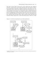
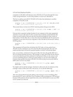
Figure 5.1 lists each of the MPEG-4 Visual profiles (left-hand column) and visual object
types (top row). The table entries indicate which object types are contained within each
profile. For example, a CODEC compatible with Simple Profile must be capable of coding
and decoding Simple objects and a Core Profile CODEC must be capable of coding and
decoding Simple and Core objects.
Profiles are an important mechanism for encouraging interoperability between CODECs
from different manufacturers. The MPEG-4 Visualstandard describes a diverse range of coding
tools and it is unlikely that any commercial CODEC would require the implementation of all the
tools. Instead, a CODEC designer chooses a profile that contains adequate tools for the target
application. For example, a basic CODEC implemented on a low-power processor may use
Simple profile, a CODEC for streaming video applications may choose Advanced Real Time
Simple and so on. To date, some profiles have had more of an impact on the marketplace than
others. The Simple and Advanced Simple profiles are particularly popular with manufacturers
and users whereas the profiles for the coding of arbitrary-shaped objects have had very limited
commercial impact (see Chapter 8 for further discussion of the commercial impact of MPEG-4
Profiles).
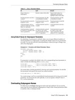
Profiles define a subset of coding tools and Levels define constraints on the parameters
of the bitstream. Table 5.3 lists the Levels for the popular Simple-based profiles (Simple,
OVERVIEW OF MPEG-4 VISUAL (NATURAL VIDEO CODING)
•
103
Table 5.3 Levels for Simple-based profiles
Profile Level Typical resolution Max. bitrate Max. objects
Simple L0 176 × 144 64 kbps 1 simple
L1 176 × 144 64 kbps 4 simple
L2 352 × 288 128 kbps 4 simple
L3 352 × 288 384 kbps 4 simple
Advanced Simple (AS) L0 176 × 144 128 kbps 1 AS or simple
L1 176 × 144 128 kbps 4 AS or simple
L2 352 × 288 384 kbps 4 AS or simple
L3 352 × 288 768 kbps 4 AS or simple
L4 352 × 576 3 Mbps 4 AS or simple
L5 720 × 576 8 Mbps 4 AS or simple
Advanced Real-Time L1 176 × 144 64 kbps 4 ARTS or simple
Simple (ARTS)
L2 352 × 288 128 kbps 4 ARTS or simple
L3 352 × 288 384 kbps 4 ARTS or simple
L4 352 × 288 2 Mbps 16 ARTS or simple
Advanced Simple and Advanced Real Time Simple). Each Level places constraints on the
maximum performance required to decode an MPEG-4 coded sequence. For example, a mul-
timedia terminal with limited processing capabilities and a small amount of memory may only
support Simple Profile @ Level 0 bitstream decoding. The Level definitions place restrictions
on the amount of buffer memory, the decoded frame size and processing rate (in macroblocks
per second) and the number of video objects (one in this case, a single rectangular frame).
A terminal that can cope with these parameters is guaranteed to be capable of successfully
decoding any conforming Simple Profile @ Level 0 bitstream. Higher Levels of Simple Profile
require a decoder to handle up to four Simple Profile video objects (for example, up to four
rectangular objects covering the QCIF or CIF display resolution).
5.2.3 Video Objects
One of the key contributions of MPEG-4 Visual is a move away from the ‘traditional’ view of a
video sequence as being merely a collection of rectangular frames of video. Instead, MPEG-4
Visual treats a video sequence as a collection of one or more video objects. MPEG-4 Visual
defines a video object as a flexible ‘entity that a user is allowed to access (seek, browse) and
manipulate (cut and paste)’ [1]. A video object (VO) is an area of the video scene that may
occupy an arbitrarily-shaped region and may exist for an arbitrary length of time. An instance
of a VO at a particular point in time is a video object plane (VOP).
This definition encompasses the traditional approach of coding complete frames, in which
each VOP is a single frame of video and a sequence of frames forms a VO (for example,
Figure 5.2 shows a VO consisting of three rectangular VOPs). However, the introduction of
the VO concept allows more flexible options for coding video. Figure 5.3 shows a VO that
consists of three irregular-shaped VOPs, each one existing within a frame and each coded
separately (object-based coding).
MPEG-4 VISUAL
•
104
video object
VOP1 VOP3VOP2
Time
Figure 5.2 VOPs and VO (rectangular)
VOP1
VOP3
VOP2
Time
Figure 5.3 VOPs and VO (arbitrary shape)
A video scene (e.g. Figure 5.4) may be made up of a background object (VO3 in this ex-
ample) and a number of separate foreground objects (VO1, VO2). This approach is potentially
much more flexible than the fixed, rectangular frame structure of earlier standards. The sep-
arate objects may be coded with different visual qualities and temporal resolutions to reflect
their ‘importance’ to the final scene, objects from multiple sources (including synthetic and
‘natural’ objects) may be combined in a single scene and the composition and behaviour of the
scene may be manipulated by an end-user in highly interactive applications. Figure 5.5 shows
a new video scene formed by adding VO1 from Figure 5.4, a new VO2 and a new background
VO. Each object is coded separately using MPEG-4 Visual (the compositing of visual and
audio objects is assumed to be handled separately, for example by MPEG-4 Systems [2]).
5.3 CODING RECTANGULAR FRAMES
Notwithstanding the potential flexibility offered by object-based coding, the most popular
application of MPEG-4 Visual is to encode complete frames of video. The tools required
CODING RECTANGULAR FRAMES
•
105
Figure 5.4 Video scene consisting of three VOs
Figure 5.5 Video scene composed of VOs from separate sources
to handle rectangular VOPs (typically complete video frames) are grouped together in the
so-called simple profiles. The tools and objects for coding rectangular frames are shown in
Figure 5.6. The basic tools are similar to those adopted by previous video coding standards,
DCT-based coding of macroblocks with motion compensated prediction. The Simple profile
is based around the well-known hybrid DPCM/DCT model (see Chapter 3, Section 3.6) with
MPEG-4 VISUAL
•
106
Advanced
Simple
Advanced Real
Time Simple
Simple
Global MC
Interlace
B-VOP
Alternate Quant
Quarter Pel
Dynamic
Resolution
Conversion
NEWPRED
Object
Tool
Short Header
I-VOP
P-VOP
4MV
UMV
Intra Pred
Video packets
Data Partitioning
RVLCs
Key:
Figure 5.6 Tools and objects for coding rectangular frames
additional tools to improve coding efficiency and transmission efficiency. Because of the
widespread popularity of Simple profile, enhanced profiles for rectangular VOPs have been
developed. The Advanced Simple profile improves further coding efficiency and adds support
for interlaced video and the Advanced Real-Time Simple profile adds tools that are useful for
real-time video streaming applications.
5.3.1 Input and output video format
The input to an MPEG-4 Visual encoder and the output of a decoder is a video sequence in
4:2:0, 4:2:2 or 4:4:4 progressive or interlaced format (see Chapter 2). MPEG-4 Visual uses the
sampling arrangement shown in Figure 2.11 for progressive sampled frames and the method
shown in Figure 2.12 for allocating luma and chroma samples to each pair of fields in an
interlaced sequence.
5.3.2 The Simple Profile
A CODEC that is compatible with Simple Profile should be capable of encoding and decoding
Simple Video Objects using the following tools:
r
I-VOP (Intra-coded rectangular VOP, progressive video format);
r
P-VOP (Inter-coded rectangular VOP, progressive video format);
CODING RECTANGULAR FRAMES
•
107
source
frame
DCT Q Reorder RLE VLE
decoded
frame
IDCT Q
-1
Reorder RLD VLD
coded
I-VOP
Figure 5.7 I-VOP encoding and decoding stages
source
frame
DCT
Q
Reorder RLE VLE
decoded
frame
IDCT
Q
-1
Reorder RLD VLD
coded
P-VOP
MCP
ME
MCR
reconstructed
frame
Figure 5.8 P-VOP encoding and decoding stages
r
short header (mode for compatibility with H.263 CODECs);
r
compression efficiency tools (four motion vectors per macroblock, unrestricted motion
vectors, Intra prediction);
r
transmission efficiency tools (video packets, Data Partitioning, Reversible Variable Length
Codes).
5.3.2.1 The Very Low Bit Rate Video Core
The Simple Profile of MPEG-4 Visual uses a CODEC model known as the Very Low Bit Rate
Video (VLBV) Core (the hybrid DPCM/DCT model described in Chapter 3). In common with
other standards, the architecture of the encoder and decoder are not specified in MPEG-4
Visual but a practical implementation will require to carry out the functions shown in
Figure 5.7 (coding of Intra VOPs) and Figure 5.8 (coding of Inter VOPs). The basic tools
required to encode and decode rectangular I-VOPs and P-VOPs are described in the next
section (Section 3.6 of Chapter 3 provides a more detailed ‘walk-through’ of the encoding
and decoding process). The tools in the VLBV Core are based on the H.263 standard and the
‘short header’ mode enables direct compatibility (at the frame level) between an MPEG-4
Simple Profile CODEC and an H.263 Baseline CODEC.
5.3.2.2 Basic coding tools
I-VOP
A rectangular I-VOP is a frame of video encoded in Intra mode (without prediction from any
other coded VOP). The encoding and decoding stages are shown in Figure 5.7.
MPEG-4 VISUAL
•
108
Table 5.4 Values of dc scaler parameter depending on QP range
Block type QP ≤ 45≤ QP ≤ 89≤ QP ≤ 24 25 ≤ QP
Luma 8 2 × QP QP + 8(2× QP) − 16
Chroma 8 (QP + 13)/2 (QP + 13)/2 QP − 6
DCT and IDCT: Blocks of luma and chroma samples are transformed using an 8 × 8 Forward
DCT during encoding and an 8 × 8 Inverse DCT during decoding (see Section 3.4).
Quantisation: The MPEG-4 Visual standard specifies the method of rescaling (‘inverse quan-
tising’) quantised transform coefficients in a decoder. Rescaling is controlled by a quantiser
scale parameter, QP, which can take values from 1 to 31 (larger values of QP produce a
larger quantiser step size and therefore higher compression and distortion). Two methods
of rescaling are described in the standard: ‘method 2’ (basic method) and ‘method 1’ (more
flexible but also more complex). Method 2 inverse quantisation operates as follows. The
DC coefficient in an Intra-coded macroblock is rescaled by:
DC = DC
Q
. dc scaler (5.1)
DC
Q
is the quantised coefficient, DC is the rescaled coefficient and dc scaler is a parameter
defined in the standard. In short header mode (see below), dc
scaler is 8 (i.e. all Intra DC
coefficients are rescaled by a factor of 8), otherwise dc
scaler is calculated according to the
value of QP (Table 5.4). All other transform coefficients (including AC and Inter DC) are
rescaled as follows:
|F |=QP · (2 ·|F
Q
|+1) (if QP is odd and F
Q
= 0)
|F |=QP · (2 ·|F
Q
|+1) − 1 (if QP is even and F
Q
= 0)
F = 0 (if F
Q
= 0)
(5.2)
F
Q
is the quantised coefficient and F is the rescaled coefficient. The sign of F is made the
same as the sign of F
Q
. Forward quantisation is not defined by the standard.
Zig-zag scan: Quantised DCT coefficients are reordered in a zig-zag scan prior to encoding
(see Section 3.4).
Last-Run-Level coding: The array of reordered coefficients corresponding to each block is
encoded to represent the zero coefficients efficiently. Each nonzero coefficient is encoded
as a triplet of (last, run, level), where ‘last’ indicates whether this is the final nonzero
coefficient in the block, ‘run’ signals the number of preceding zero coefficients and ‘level’
indicates the coefficient sign and magnitude.
Entropy coding: Header information and (last, run, level) triplets (see Section 3.5) are repre-
sented by variable-length codes (VLCs). These codes are similar to Huffman codes and are
defined in the standard, based on pre-calculated coefficient probabilities
A coded I-VOP consists of a VOP header, optional video packet headers and coded mac-
roblocks. Each macroblock is coded with a header (defining the macroblock type, identifying
which blocks in the macroblock contain coded coefficients, signalling changes in quantisation
parameter, etc.) followed by coded coefficients for each 8 × 8 block.
CODING RECTANGULAR FRAMES
•
109
In the decoder, the sequence of VLCs are decoded to extract the quantised transform
coefficients which are re-scaled and transformed by an 8 × 8 IDCT to reconstruct the decoded
I-VOP (Figure 5.7).
P-VOP
A P-VOP is coded with Inter prediction from a previously encoded I- or P-VOP (a reference
VOP). The encoding and decoding stages are shown in Figure 5.8.
Motion estimation and compensation: The basic motion compensation scheme is block-
based compensation of 16 × 16 pixel macroblocks (see Chapter 3). The offset between the
current macroblock and the compensation region in the reference picture (the motion vector)
may have half-pixel resolution. Predicted samples at sub-pixel positions are calculated us-
ing bilinear interpolation between samples at integer-pixel positions. The method of motion
estimation (choosing the ‘best’ motion vector) is left to the designer’s discretion. The match-
ing region (or prediction) is subtracted from the current macroblock to produce a residual
macroblock (Motion-Compensated Prediction, MCP in Figure 5.8).
After motion compensation, the residual data is transformed with the DCT, quantised,
reordered, run-level coded and entropy coded. The quantised residual is rescaled and inverse
transformed in the encoder in order to reconstruct a local copy of the decoded MB (for
further motion compensated prediction). A coded P-VOP consists of VOP header, optional
video packet headers and coded macroblocks each containing a header (this time including
differentially-encoded motion vectors) and coded residual coefficients for every 8 × 8 block.
The decoder forms the same motion-compensated prediction based on the received motion
vector and its own local copy of the reference VOP. The decoded residual data is added to the
prediction to reconstruct a decoded macroblock (Motion-Compensated Reconstruction, MCR
in Figure 5.8).
Macroblocks within a P-VOP may be coded in Inter mode (with motion compensated
prediction from the reference VOP) or Intra mode (no motion compensated prediction). Inter
mode will normally give the best coding efficiency but Intra mode may be useful in regions
where there is not a good match in a previous VOP, such as a newly-uncovered region.
Short Header
The ‘short header’ tool provides compatibility between MPEG-4 Visual and the ITU-T H.263
video coding standard. An I- or P-VOP encoded in ‘short header’ mode has identical syntax
to an I-picture or P-picture coded in the baseline mode of H.263. This means that an MPEG-4
I-VOP or P-VOP should be decodeable by an H.263 decoder and vice versa.
In short header mode, the macroblocks within a VOP are organised in Groups of Blocks
(GOBs), each consisting of one or more complete rows of macroblocks. Each GOB may
(optionally) start with a resynchronisation marker (a fixed-length binary code that enables a
decoder to resynchronise when an error is encountered, see Section 5.3.2.4).
5.3.2.3 Coding Efficiency Tools
The following tools, part of the Simple profile, can improve compression efficiency. They are
only used when short header mode is not enabled.
MPEG-4 VISUAL
•
110
Figure 5.9 One or four vectors per macroblock
Four motion vectors per macroblock
Motion compensation tends to be more effective with smaller block sizes. The default block
size for motion compensation is 16 × 16 samples (luma), 8 × 8 samples (chroma), resulting
in one motion vector per macroblock. This tool gives the encoder the option to choose a
smaller motion compensation block size, 8 × 8 samples (luma) and 4 × 4 samples (chroma),
giving four motion vectors per macroblock. This mode can be more effective at minimising
the energy in the motion-compensated residual, particularly in areas of complex motion or
near the boundaries of moving objects. There is an increased overhead in sending four motion
vectors instead of one, and so the encoder may choose to send one or four motion vectors on
a macroblock-by-macroblock basis (Figure 5.9).
Unrestricted Motion Vectors
In some cases, the best match for a macroblock may be a 16 × 16 region that extends outside
the boundaries of the reference VOP. Figure 5.10 shows the lower-left corner of a current
VOP (right-hand image) and the previous, reference VOP (left-hand image). The hand hold-
ing the bow is moving into the picture in the current VOP and so there isn’t a good match
for the highlighted macroblock inside the reference VOP. In Figure 5.11, the samples in
the reference VOP have been extrapolated (‘padded’) beyond the boundaries of the VOP.
A better match for the macroblock is obtained by allowing the motion vector to point into
this extrapolated region (the highlighted macroblock in Figure 5.11 is the best match in this
case). The Unrestricted Motion Vectors (UMV) tool allows motion vectors to point outside
the boundary of the reference VOP. If a sample indicated by the motion vector is outside
the reference VOP, the nearest edge sample is used instead. UMV mode can improve mo-
tion compensation efficiency, especially when there are objects moving in and out of the
picture.
Intra Prediction
Low-frequency transform coefficients of neighbouring intra-coded 8 × 8 blocks are often
correlated. In this mode, the DC coefficient and (optionally) the first row and column of AC
coefficients in an Intra-coded 8 × 8 block are predicted from neighbouring coded blocks.
Figure 5.12 shows a macroblock coded in intra mode and the DCT coefficients for each of the
four 8 × 8 luma blocks are shown in Figure 5.13. The DC coefficients (top-left) are clearly
CODING RECTANGULAR FRAMES
•
111
Figure 5.10 Reference VOP and current VOP
Figure 5.11 Reference VOP extrapolated beyond boundary
Figure 5.12 Macroblock coded in intra mode
similar but it is less obvious whether there is correlation between the first row and column of
the AC coefficients in these blocks.
The DC coefficient of the current block (X in Figure 5.14) is predicted from the DC
coefficient of the upper (C) or left (A) previously-coded 8 × 8 block. The rescaled DC
coefficient values of blocks A, B and C determine the method of DC prediction. If A,
B or C are outside the VOP boundary or the boundary of the current video packet (see
later), or if they are not intra-coded, their DC coefficient value is assumed to be equal to
MPEG-4 VISUAL
•
112
Upper left Upper right
Lower left Lower right
500
400
300
200
100
-100
0
2
4
6
8
5
0
0
500
400
300
200
100
-100
0
2
4
6
8
5
0
0
500
400
300
200
100
-100
0
2
4
6
8
5
0
0
500
400
300
200
100
-100
0
2
4
6
8
5
0
0
Figure 5.13 DCT coefficients (luma blocks)
1024 (the DC coefficient of a mid-grey block of samples). The direction of prediction is
determined by:
if |DC
A
− DC
B
| < |DC
B
− DC
C
|
predict from block C
else
predict from block A
The direction of the smallest DC gradient is chosen as the prediction direction for block X.
The prediction, P
DC
, is formed by dividing the DC coefficient of the chosen neighbouring
CODING RECTANGULAR FRAMES
•
113
X
C
A
B
Figure 5.14 Prediction of DC coefficients
X
C
A
Figure 5.15 Prediction of AC coefficients
block by a scaling factor and P
DC
is then subtracted from the actual quantised DC coefficient
(QDC
X
) and the residual (PQDC
X
) is coded and transmitted.
AC coefficient prediction is carried out in a similar way, with the first row or column
of AC coefficients predicted in the direction determined for the DC coefficient (Figure 5.15).
For example, if the prediction direction is from block A, the first column of AC coefficients in
block X is predicted from the first column of block A. If the prediction direction is from block
C, the first row of AC coefficients in X is predicted from the first row of C. The prediction is
scaled depending on the quantiser step sizes of blocks X and A or C.
5.3.2.4 Transmission Efficiency Tools
A transmission error such as a bit error or packet loss may cause a video decoder to lose
synchronisation with the sequence of decoded VLCs. This can cause the decoder to decode
incorrectly some or all of the information after the occurrence of the error and this means
that part or all of the decoded VOP will be distorted or completely lost (i.e. the effect of the
error spreads spatially through the VOP, ‘spatial error propagation’). If subsequent VOPs are
predicted from the damaged VOP, the distorted area may be used as a prediction reference,
leading to temporal error propagation in subsequent VOPs (Figure 5.16).
MPEG-4 VISUAL
•
114
error position
forward prediction
damaged area
Figure 5.16 Spatial and temporal error propagation
When an error occurs, a decoder can resume correct decoding upon reaching a resynchro-
nisation point, typically a uniquely-decodeable binary code inserted in the bitstream. When
the decoder detects an error (for example because an invalid VLC is decoded), a suitable
recovery mechanism is to ‘scan’ the bitstream until a resynchronisation marker is detected. In
short header mode, resynchronisation markers occur at the start of each VOP and (optionally)
at the start of each GOB.
The following tools are designed to improve performance during transmission of coded
video data and are particularly useful where there is a high probability of network errors [3].
The tools may not be used in short header mode.
Video Packet
A transmitted VOP consists of one or more video packets. A video packet is analogous to
a slice in MPEG-1, MPEG-2 or H.264 (see Section 6) and consists of a resynchronisation
marker, a header field and a series of coded macroblocks in raster scan order (Figure 5.17).
(Confusingly, the MPEG-4 Visual standard occasionally refers to video packets as ‘slices’).
The resynchronisation marker is followed by a count of the next macroblock number, which
enables a decoder to position the first macroblock of the packet correctly. After this comes
the quantisation parameter and a flag, HEC (Header Extension Code). If HEC is set to 1, it
is followed by a duplicate of the current VOP header, increasing the amount of information
that has to be transmitted but enabling a decoder to recover the VOP header if the first VOP
header is corrupted by an error.
The video packet tool can assist in error recovery at the decoder in several ways, for
example:
1. When an error is detected, the decoder can resynchronise at the start of the next video
packet and so the error does not propagate beyond the boundary of the video packet.
CODING RECTANGULAR FRAMES
•
115
Sync Header HEC Macroblock data Sync(Header)
Figure 5.17 Video packet structure
2. If used, the HEC field enables a decoder to recover a lost VOP header from elsewhere
within the VOP.
3. Predictive coding (such as differential encoding of the quantisation parameter, prediction
of motion vectors and intra DC/AC prediction) does not cross the boundary between video
packets. This prevents (for example) an error in motion vector data from propagating to
another video packet.
Data Partitioning
The data partitioning tool enables an encoder to reorganise the coded data within a video
packet to reduce the impact of transmission errors. The packet is split into two partitions, the
first (immediately after the video packet header) containing coding mode information for each
macroblock together with DC coefficients of each block (for Intra macroblocks) or motion
vectors (for Inter macroblocks). The remaining data (AC coefficients and DC coefficients of
Inter macroblocks) are placed in the second partition following a resynchronisation marker.
The information sent in the first partition is considered to be the most important for adequate
decoding of the video packet. If the first partition is recovered, it is usually possible for the
decoder to make a reasonable attempt at reconstructing the packet, even if the 2nd partition is
damaged or lost due to transmission error(s).
Reversible VLCs
An optional set of Reversible Variable Length Codes (RVLCs) may be used to encode DCT
coefficient data. As the name suggests, these codes can be correctly decoded in both the
forward and reverse directions, making it possible for the decoder to minimise the picture area
affected by an error.
A decoder first decodes each video packet in the forward direction and, if an error is
detected (e.g. because the bitstream syntax is violated), the packet is decoded in the reverse
direction from the next resynchronisation marker. Using this approach, the damage caused
by an error may be limited to just one macroblock, making it easy to conceal the errored
region. Figure 5.18 illustrates the use of error resilient decoding. The figure shows a video
packet that uses HEC, data partitioning and RVLCs. An error occurs within the texture data
and the decoder scans forward and backward to recover the texture data on either side of the
error.
5.3.3 The Advanced Simple Profile
The Simple profile, introduced in the first version of the MPEG-4 Visual standard, rapidly
became popular with developers because of its improved efficiency compared with previous
standards (such as MPEG-1 and MPEG-2) and the ease of integrating it into existing video
applications that use rectangular video frames. The Advanced Simple profile was incorporated
MPEG-4 VISUAL
•
116
Sync Header HEC
Header +
MV
Texture Sync
Error
Decode in forward
direction
Decode in reverse
direction
Figure 5.18 Error recovery using RVLCs
into a later version of the standard with added tools to support improved compression efficiency
and interlaced video coding. An Advanced Simple Profile CODEC must be capable of decoding
Simple objects as well as Advanced Simple objects which may use the following tools in
addition to the Simple Profile tools:
r
B-VOP (bidirectionally predicted Inter-coded VOP);
r
quarter-pixel motion compensation;
r
global motion compensation;
r
alternate quantiser;
r
interlace (tools for coding interlaced video sequences).
B-VOP
The B-VOP uses bidirectional prediction to improve motion compensation efficiency. Each
block or macroblock may be predicted using (a) forward prediction from the previous I- or
P-VOP, (b) backwards prediction from the next I- or P-VOP or (c) an average of the forward and
backward predictions. This mode generally gives better coding efficiency than basic forward
prediction; however, the encoder must store multiple frames prior to coding each B-VOP which
increases the memory requirements and the encoding delay. Each macroblock in a B-VOP is
motion compensated from the previous and/or next I- or P-VOP in one of the following ways
(Figure 5.19).
1. Forward prediction: A single MV is transmitted, MV
F
, referring to the previous I- or
P-VOP.
2. Backward prediction: A single MV is transmitted, MV
B
, referring to the future I- or
P-VOP.
3. Bidirectional interpolated prediction: Two MVs are transmitted, MV
F
and MV
B
, referring
to the previous and the future I- or P-VOPs. The motion compensated prediction for the
current macroblock is produced by interpolating between the luma and chroma samples in
the two reference regions.
4. Bidirectional direct prediction: Motion vectors pointing to the previous and future I- or
P-VOPs are derived automatically from the MV of the same macroblock in the
future I- or P-VOP. A ‘delta MV’ correcting these automatically-calculated MVs is
transmitted.
CODING RECTANGULAR FRAMES
•
117
I B B P
temporal order
Forward Backward
Bidirectional
Figure 5.19 Prediction modes for B-VOP
MB in P
7
MB in B
6
MV
F
MV
F
MV
B
Figure 5.20 Direct mode vectors
Example of direct mode (Figure 5.20)
Previous reference VOP: I
4
, display time = 2
Current B-VOP: B
6
, display time = 6
Future reference VOP: P
7
, display time = 7
MV for same macroblock position in P
7
,MV
7
= (+5, −10)
TRB = display
time(B
6
) – display time(I
4
) = 4
TRD = display
time(P
7
) – display time(I
4
) = 5
MV
D
= 0 (no delta vector)
MV
F
= (TRB/TRD).MV = (+4, −8)
MV
B
= (TRB-TRD/TRD).MV = (−1, +2)
Quarter-Pixel Motion Vectors
The Simple Profile supports motion vectors with half-pixel accuracy and this tool supports
vectors with quarter-pixel accuracy. The reference VOP samples are interpolated to half-pixel
positions and then again to quarter-pixel positions prior to motion estimation and compensa-
tion. This increases the complexity of motion estimation, compensation and reconstruction
MPEG-4 VISUAL
•
118
Table 5.5 Weighting matrix W
w
10 20 20 30 30 30 40 40
20 20 30 30 30 40 40 40
20 30 30 30 40 40 40 40
30 30 30 30 40 40 40 50
30 30 30 40 40 40 50 50
30 40 40 40 40 40 50 50
40 40 40 40 50 50 50 50
40 40 40 50 50 50 50 50
but can provide a gain in coding efficiency compared with half-pixel compensation (see
Chapter 3).
Alternate quantiser
An alternative rescaling (‘inverse quantisation’) method is supported in the Advanced Simple
Profile. Intra DC rescaling remains the same (see Section 5.3.2) but other quantised coefficients
may be rescaled using an alternative method
1
.
Quantised coefficients F
Q
(u,v) are rescaled to produce coefficients F(u,v) (where u,
vare the coordinates of the coefficient) as follows:
F = 0ifF
Q
= 0
F = [(2.F
Q
(u,v) + k) · W
w
(u,v) · QP]/16 if F
Q
= 0
(5.3)
k =
0 intra blocks
+1 F
Q
(u,v) > 0, nonintra
−1 F
rmQ
(u,v) < 0, nonintra
where W
W
is a matrix of weighting factors, W
0
for intra macroblocks and W
1
for nonintra
macroblocks. In Method 2 rescaling (see Section 5.3.2.1), all coefficients (apart from Intra
DC) are quantised and rescaled with the same quantiser step size. Method 1 rescaling allows an
encoder to vary the step size depending on the position of the coefficient, using the weighting
matrix W
W
. For example, better subjective performance may be achieved by increasing the step
size for high-frequency coefficients and reducing it for low-frequency coefficients. Table 5.5
shows a simple example of a weighting matrix W
W
.
Global Motion Compensation
Macroblocks within the same video object may experience similar motion. For example,
camera pan will produce apparent linear movement of the entire scene, camera zoom or rotation
will produce a more complex apparent motion and macroblocks within a large object may
all move in the same direction. Global Motion Compensation (GMC) enables an encoder to
transmit a small number of motion (warping) parameters that describe a default ‘global’ motion
for the entire VOP. GMC can provide improved compression efficiency when a significant
number of macroblocks in the VOP share the same motion characteristics. The global motion
1
The MPEG-4 Visual standard describes the default rescaling method as ‘Second Inverse Quantisation Method’ and
the alternative, optional method as ‘First Inverse Quantisation Method’. The default (‘Second’) method is sometimes
known as ‘H.263 quantisation’ and the alternative (‘First’) method as ‘MPEG-4 quantisation’.
CODING RECTANGULAR FRAMES
•
119
Interpolated MV
Global MV
Figure 5.21 VOP, GMVs and interpolated vector
Figure 5.22 GMC (compensating for rotation)
parameters are encoded in the VOP header and the encoder chooses either the default GMC
parameters or an individual motion vector for each macroblock.
When the GMC tool is used, the encoder sends up to four global motion vectors (GMVs)
for each VOP together with the location of each GMV in the VOP. For each pixel position in
the VOP, an individual motion vector is calculated by interpolating between the GMVs and
the pixel position is motion compensated according to this interpolated vector (Figure 5.21).
This mechanism enables compensation for a variety of types of motion including rotation
(Figure 5.22), camera zoom (Figure 5.23) and warping as well as translational or linear
motion.
The use of GMC is enabled by setting the parameter sprite
enable to ‘GMC’ in a Video
Object Layer (VOL) header. VOPs in the VOL may thereafter be coded as S(GMC)-VOPs
(‘sprite’ VOPs with GMC), as an alternative to the ‘usual’ coding methods (I-VOP, P-VOP
or B-VOP). The term ‘sprite’ is used here because a type of global motion compensation is
applied in the older ‘sprite coding’ mode (part of the Main Profile, see Section 5.4.2.2).
MPEG-4 VISUAL
•
120
Figure 5.23 GMC (compensating for camera zoom)
Figure 5.24 Close-up of interlaced VOP
Interlace
Interlaced video consists of two fields per frame (see Chapter 2) sampled at different times
(typically at 50 Hz or 60 Hz temporal sampling rate). An interlaced VOP contains alternate
lines of samples from two fields. Because the fields are sampled at different times, horizontal
movement may reduce correlation between lines of samples (for example, in the moving face
in Figure 5.24). The encoder may choose to encode the macroblock in Frame DCT mode,
in which each block is transformed as usual, or in Field DCT mode, in which the luminance
samples from Field 1 are placed in the top eight lines of the macroblock and the samples from
Field 2 in the lower eight lines of the macroblock before calculating the DCT (Figure 5.25).
Field DCT mode gives better performance when the two fields are decorrelated.
In Field Motion Compensation mode (similar to 16 × 8 Motion Compensation Mode
in the MPEG-two standard), samples belonging to the two fields in a macroblock are motion
CODING RECTANGULAR FRAMES
•
121
.
.
.
Figure 5.25 Field DCT
compensated separately so that two motion vectors are generated for the macroblock, one
for the first field and one for the second. The Direct Mode used in B-VOPs (see above) is
modified to deal with macroblocks that have Field Motion Compensated reference blocks. Two
forward and two backward motion vectors are generated, one from each field in the forward
and backward directions. If the interlaced video tool is used in conjunction with object-based
coding (see Section 5.4), the padding process may be applied separately to the two fields of a
boundary macroblock.
5.3.4 The Advanced Real Time Simple Profile
Streaming video applications for networks such as the Internet require good compression and
error-robust video coding tools that can adapt to changing network conditions. The coding
and error resilience tools within Simple Profile are useful for real-time streaming applications
and the Advanced Real Time Simple (ARTS) object type adds further tools to improve error
resilience and coding flexibility, NEWPRED (multiple prediction references) and Dynamic
Resolution Conversion (also known as Reduced Resolution Update). An ARTS Profile CODEC
should support Simple and ARTS object types.
NEWPRED
The NEWPRED (‘new prediction’) tool enables an encoder to select a prediction reference
VOP from any of a set of previously encoded VOPs for each video packet. A transmission
error that is imperfectly concealed will tend to propagate temporally through subsequent
predicted VOPs and NEWPRED can be used to limit temporal propagation as follows (Figure
5.26). Upon detecting an error in a decoded VOP (VOP1 in Figure 5.26), the decoder sends a
feedback message to the encoder identifying the errored video packet. The encoder chooses
a reference VOP prior to the errored packet (VOP 0 in this example) for encoding of the
following VOP (frame 4). This has the effect of ‘cleaning up’ the error and halting temporal
propagation. Using NEWPRED in this way requires both encoder and decoder to store multiple
reconstructed VOPs to use as possible prediction references. Predicting from an older reference
VOP (4 VOPs in the past in this example) tends to reduce compression performance because
the correlation between VOPs reduces with increasing time.
MPEG-4 VISUAL
•
122
Encoder
Decoder
initial error
feedback
indication
predict from older reference VOP
predict from older reference VOP
012345
01234
Figure 5.26 NEWPRED error handling
Dynamic Resolution Conversion
Dynamic Resolution Conversion (DRC), otherwise known as Reduced Resolution (RR) mode,
enables an encoder to encode a VOP with reduced spatial resolution. This can be a useful tool
to prevent sudden increases in coded bitrate due to (for example) increased detail or rapid
motion in the scene. Normally, such a change in the scene content would cause the encoder to
generate a large number of coded bits, causing problems for a video application transmitting
over a limited bitrate channel. Using the DRC tool, a VOP is encoded at half the normal
horizontal and vertical resolution. At the decoder, a residual macroblock within a Reduced
Resolution VOP is decoded and upsampled (interpolated) so that each 8 × 8 luma block covers
an area of 16 × 16 samples. The upsampled macroblock (now covering an area of 32 × 32
luma samples) is motion compensated from a 32 × 32-sample reference area (the motion
vector of the decoded macroblock is scaled up by a factor of 2) (Figure 5.27). The result is
that the Reduced Resolution VOP is decoded at half the normal resolution (so that the VOP
detail is reduced) with the benefit that the coded VOP requires fewer bits to transmit than a
full-resolution VOP.
5.4 CODING ARBITRARY-SHAPED REGIONS
Coding objects of arbitrary shape (see Section 5.2.3) requires a number of extensions to
the block-based VLBV core CODEC [4]. Each VOP is coded using motion compensated
prediction and DCT-based coding of the residual, with extensions to deal with the special
cases introduced by object boundaries. In particular, it is necessary to deal with shape coding,
motion compensation and texture coding of arbitrary-shaped video objects.
CODING ARBITRARY-SHAPED REGIONS
•
123
Y
Cr Cb
16
16
8
8
Y
Cr Cb
16
16
32
32
Y
Cr Cb
16
16
32
32
upsample
motion
compensate
32x32 sample
reference area
decoded
macroblock
Figure 5.27 Reduced Resolution decoding of a macroblock
Shape coding: The shape of a video object is defined by Alpha Blocks, each covering a
16 × 16-pixel area of the video scene. Each Alpha Block may be entirely external to the
video object (in which case nothing needs to be coded), entirely internal to the VO (in
which case the macroblock is encoded as in Simple Profile) or it may cross a boundary
of the VO. In this last case, it is necessary to define the shape of the VO edge within the
Alpha Block. Shape information is defined using the concept of ‘transparency’, where a
‘transparent’ pixel is not part of the current VOP, an ‘opaque’ pixel is part of the VOP
and replaces anything ‘underneath’ it and a ‘semi-transparent’ pixel is part of the VOP
and is partly transparent. The shape information may be defined as binary (all pixels are
either opaque, 1, or transparent, 0) or grey scale (a pixel’s transparency is defined by a
number between 0, transparent, and 255, opaque). Binary shape information for a boundary
macroblock is coded as a binary alpha block (BAB) using arithmetic coding and grey scale
shape information is coded using motion compensation and DCT-based encoding.
Motion compensation: Each VOP may be encoded as an I-VOP (no motion compensation),
a P-VOP (motion compensated prediction from a past VOP) or a B-VOP (bidirection mo-
tion compensated prediction). Nontransparent pixels in a boundary macroblock are motion
compensated from the appropriate reference VOP(s) and the boundary pixels of a reference
MPEG-4 VISUAL
•
124
Simple
Advanced
Coding
Efficiency
N-Bit
N-Bit
Core
Core
Main
Core
B-VOP
Alternate Quant
PVOP temporal
scalability
Binary shape
Gray shape
Interlace
Sprite
Gray shape
Interlace
Quarter pel
Global MC
Shape adaptive
DCT
Figure 5.28 Tools and objects for coding arbitrary-shaped regions
VOP are ‘padded’ to the edges of the motion estimation search area to fill the transparent
pixel positions with data.
Texture coding: Motion-compensated residual samples (‘texture’) in internal blocks are coded
using the 8 × 8 DCT, quantisation and variable length coding described in Section 5.3.2.1.
Non-transparent pixels in a boundary block are padded to the edge of the 8 × 8 block prior
to applying the DCT.
Video object coding is supported by the Core and Main profiles, with extra tools in the
Advanced Coding Efficiency and N-Bit profiles (Figure 5.28).
5.4.1 The Core Profile
A Core Profile CODEC should be capable of encoding and decoding Simple Video Objects
and Core Video Objects. A Core VO may use any of the Simple Profile tools plus the following: