The next great telecom revolution phần 5 pps
Bạn đang xem bản rút gọn của tài liệu. Xem và tải ngay bản đầy đủ của tài liệu tại đây (363.57 KB, 25 trang )
4.1.2 Next-Generation Telecom Network
Several scientists, working in collaboration, are laying the groundwork for a
new wireless and optical fiber-based telecommunications network that aims to
bring reliable, high-speed Internet access to every home and small business in
the United States within the next few years.
Funded by a five-year, $7.5 million National Science Foundation grant, the
“100 Megabits to 100 Million Homes” research project brings together scien-
tists from Carnegie Mellon University, Fraser Research, Rice University,
the University of California at Berkeley, Stanford University, Internet2, the
Pittsburgh Supercomputing Center, and AT&T Research. The coalition
believes that the growing demand for communications, combined with newly
emerging technologies, has created a once-a-century opportunity to upgrade
the nation’s network infrastructure.
“What the copper-wired telephone network was to the 20th century, the
fiber network will be to the 21st,” says Hui Zhang, the project’s principal inves-
tigator and a Carnegie Mellon associate professor of computer science.“Today
we have 500 kilobits reaching 10 million American homes,” he notes. Zhang
is looking toward creating a system 100 times faster and that reaches 10 times
more households. “We must make the system more manageable, more secure,
more economical, and more scalable, and we must create an infrastructure that
can support applications not yet envisioned,” he says.
The creation of a network to serve 100 million households with two-way
symmetric data communications service at 100 megabits per second is a
tremendous challenge that reaches far beyond technological issues. Universal
availability of such a network promises to bring fundamental changes to daily
life and could substantially raise its users’ standard of living. Barriers to the
network’s creation, however, extend beyond straightforward deployment and
cost issue—fundamental innovations in the way networks are organized and
managed are also an issue. Additionally, the researchers must develop com-
munication architectures that are particularly well suited to very large-scale
deployment and that can operate inexpensively at very high speeds.
To achieve their goal, the collaborators plan to start with basic principles
and undertake fundamental research that addresses the design of an eco-
nomical, robust, secure, and scalable 100 ¥ 100 network. Then, they will con-
struct proof-of-concept demonstrations to show how the network can be built.
Initially, the scientists will produce a framework of what such a network
might look like. Then, the network’s proposed architecture and design will
be disseminated to government and industry through presentations and
partnerships so it can serve as a guide to business investment in network
development.
Zhang notes that the physical testbeds created through the project will
serve as a basis for further studies, such as social science research on the impact
of connectivity in the home. The software and tools used to design and vali-
date the network, particularly the emulation systems, will be used to create
FASTER NETWORKS 81
c4.qxd 8/30/04 2:39 PM Page 81
new curricula for network education in two- and four-year colleges. In fact,
plans are already under way for an outreach program. “We will attack pieces
of the problem according to our expertise and get together to hash out the
architecture and develop some initial answers,” Zhang says. He expects to have
an experimental component at the end of the project in five years.
The Internet has made a huge impact on society, but there are limits to
today’s network technology, notes Zhang. “We must not be satisfied by the
Internet’s apparent success,” he says. “Breakthroughs over the last 30 years
have masked its underlying problems. We need to take a fresh look at the
architecture considering new requirements and the technology that has
changed profoundly in the last three decades. The biggest challenge is to
imagine the network beyond the Internet.”
4.2 NEW OPTICAL MATERIALS
Organic electro-optic polymers have long held the promise of vastly improv-
ing many different types of telecom technologies. It now appears that scien-
tists are on the verge of breakthroughs that will bring dramatic progress in
such materials as well as the devices in which they are used.
Electro-optic polymers are used to make devices that take information that
has typically been transmitted electronically and transfer it to light-based
optical systems. The latest developments will affect not just how much infor-
mation can be sent at one time but also the power needed to transmit the
information.
The capabilities of the most recently developed materials are about five
times greater than those of standard lithium niobate crystals, the best natu-
rally occurring material for transferring data from electronic to optical trans-
mission and for many years the industry standard. The newest materials
require less than one-fifth the voltage (under 1 volt) needed for lithium
niobate.“What this shows is that people have done far better than nature could
ever do in this process,” says Larry Dalton, a University of Washington chem-
istry professor and director of the Science & Technology Center on Materials
and Devices for Information Technology Research. “The reason we’re seeing
improved performance is the rational design of new materials with new
properties.” The newest materials represent a nearly fivefold improvement in
capability in just four years. At that rate, material capabilities will soon
reach benchmarks set for 2006 by the National Science Foundation.
Recent advancements are making possible technologies that were previ-
ously only a fanciful vision, says Dalton. For example, components can now
be made so small and power efficient that they can be arranged in flexible,
foldable formats yet experience no optical loss or change in power require-
ments until the material is wrapped around a cylinder as tiny as 1.5mm, a little
bigger than a paper clip.
82 THE FUTURE IS FIBER—OPTICAL TECHNOLOGIES
c4.qxd 8/30/04 2:39 PM Page 82
Such materials can be used to create space-based phased array radar
systems for surveillance and telecommunications applications. Each face of a
phased array typically has thousands of elements that work in a complex inter-
dependence. A major advantage of the new material is that the entire radar
system can be launched in a very compact form and then unfurled to its full
form once it reaches orbit. Deployment costs can be greatly reduced because
of low power requirements and the much-reduced weight of the material being
sent into space.According to Dalton, techniques to mass produce the tiny fold-
able components, which should reduce costs even further, are currently being
developed.
The newest materials have immediate applications in a number of other
technologies as well, Dalton says. For instance, photonic elements can make it
possible for a mobile phone to transmit a large amount of data with very low
power requirements, allowing a device that is very efficient to also be made
very compact. Similarly, the materials can bring greater efficiency and afford-
ability to optical gyroscope systems, commonly used in aircraft navigation but
also adaptable for other uses—such as vehicle navigation systems—if costs are
low enough.
Additionally, photonics can replace coaxial cable in many satellite systems,
reducing the weight of certain components as much as 75 percent. “The cost
of getting something up into space is horrendous because of weight, so any-
thing that reduces weight and power requirements is of immediate impor-
tance,” Dalton says.
4.2.1 New Glasses
Researchers have developed a new family of glasses that will bring higher
power to smaller lasers and optical devices and provide a less-expensive alter-
native to many other optical glasses and crystals, like sapphire. Called REAl
Glass (rare earth aluminum oxide), the materials are durable, provide a good
host for atoms that improve laser performance, and may extend the range of
wavelengths that a single laser can currently produce (Fig. 4-1).
With support from the National Science Foundation (NSF), Containerless
Research Inc. (CRI), based in the Northwestern University Evanston
Research Park in Illinois, recently developed the REAl Glass manufacturing
process. NSF is now supporting the company to develop the glasses for
applications in power lasers, surgical lasers, optical communications devices,
infrared materials, and sensors that may detect explosives and toxins.
“NSF funded the technology at a stage when there were very few compa-
nies or venture capitalists that would have made the choice to invest,” says
Winslow Sargeant, the NSF officer who oversees CRI’s Small Business
Innovation Research (SBIR) award. “We supported the REAl Glass research
because we saw there was innovation there,” adds Sargeant. “They are a great
company with a good technology, so we provided seed money to establish the
NEW OPTICAL MATERIALS 83
c4.qxd 8/30/04 2:39 PM Page 83
technology’s feasibility. Right now, we can say the feasibility is clear, and
they’re one step closer to full-scale manufacturability,” he says.
CRI originally developed the glasses with funding from NASA. The
research used containerless processing techniques, including a specialized
research facility—the Electrostatic Levitator—at the NASA Marshall Space
Flight Center in Huntsville, Alabama. With the NASA device, the researchers
levitated the materials using static electricity and then heated the substances
to extremely high temperatures. In that process, the materials were completely
protected against contact with a surrounding container or other sources of
contamination.
“The research that led to the development of REAl Glass concerned the
nature and properties of ‘fragile’ liquids, substances that are very sensitive to
temperature and have a viscosity [or resistance to flow] that can change rapidly
when the temperature drops,” says Richard Weber, the CRI principal investi-
gator on the project.
REAl Glass, like many other glasses, is made from a supercooled liquid.
This means that the liquid cooled quickly enough to prevent its atoms from
organizing and forming a crystal structure. At lower temperatures, such as
room temperature, the atoms are “fixed” in this jumbled, glassy state. In REAl
Glass, the glass-making process also provides a mechanism for incorporating
84 THE FUTURE IS FIBER—OPTICAL TECHNOLOGIES
Figure 4-1 REAl Glass (Rare Earth Aluminum oxide).
c4.qxd 8/30/04 2:39 PM Page 84
rare-earth elements in a uniform way. This quality makes REAl Glass
particularly attractive for laser applications.
After CRI scientists spent several years on fundamental research into
fragile liquids, NSF provided funds to develop both patented glasses and pro-
prietary manufacturing processes for combining the glass components in com-
mercial quantities and at a much lower cost than for levitation melting. Using
high-temperature melting and forming operations, CRI is making REAl Glass
in 10-mm-thick rods and plates, establishing a basis for inexpensive, large-scale
production of sheet and rod products.
“The REAl Glass products are a new family of optical materials,” says
Weber, who adds that CRI is already meeting with businesses to talk about
requirements for laser, infrared window, and other optical applications and
supplying finished products or licensing the material for use.
“The REAl Glass technology combines properties of competing materials
into one [material],” says NSF’s Sargeant. “With these glasses,” he adds,
“researchers can design smaller laser devices, because of the high-power
density that can be achieved, and can provide small, high-bandwidth devices
for applications in the emerging fiber-to-the-home telecom market.”
Because the glass can incorporate a variety of rare-earth elements into its
structure, CRI can craft the glasses to yield specific properties, such as the
ability to tune a laser across multiple light wavelengths, which can have impor-
tant implications for the lasers used in dental procedures and surgery, for
example, providing more control for operations involving skin shaping or
cauterization.
The Air Force Office of Scientific Research is supporting CRI’s research
into applications, including materials for infrared waveguides and sensors
needed to identify chemical components. CRI is also continuing basic research
on fragile oxide liquids, which they believe still offer much potential for
generating new materials and ultimately optical devices.
4.2.2 Optical Fibers in Sponges
Scientists at Lucent Technologies’ Bell Labs have found that a deep-sea
sponge contains optical fiber that is remarkably similar to the optical fiber
found in today’s state-of-the-art telecommunications networks. The deep-sea
sponge’s glass fiber, designed through the course of evolution, may possess
certain technological advantages over industrial optical fiber.“We believe this
novel biological optical fiber may shed light upon new bio-inspired processes
that may lead to better fiber optic materials and networks,” says Joanna
Aizenberg, the Bell Labs materials scientist who led the research team.
“Mother Nature’s ability to perfect materials is amazing, and the more we
study biological organisms, the more we realize how much we can learn from
them.”
The sponge in the study, Euplectella, lives in the depths of the ocean in the
tropics and grows to about half a foot in length. Commonly known as the
NEW OPTICAL MATERIALS 85
c4.qxd 8/30/04 2:39 PM Page 85
Venus Flower Basket, it has an intricate cylindrical mesh-like skeleton of
glassy silica, often inhabited by a pair of mating shrimp. At the base of the
sponge’s skeleton is a tuft of fibers that extends outward like an inverted
crown.Typically, these fibers are between two and seven inches long and about
the thickness of a human hair.
The Bell Labs team found that each of the sponge’s fibers comprises dis-
tinct layers with different optical properties. Concentric silica cylinders with
high organic content surround an inner core of high-purity silica glass, a struc-
ture similar to industrial optical fiber, in which layers of glass cladding sur-
round a glass core of slightly different composition. The researchers found
during experiments that the biological fibers of the sponge conducted light
beautifully when illuminated and found them to use the same optical princi-
ples that modern engineers have used to design industrial optical fiber.“These
biological fibers bear a striking resemblance to commercial telecommunica-
tions fibers, as they use the same material and have similar dimensions,” says
Aizenberg.
Although these natural bio-optical fibers do not have the superbly high
transparency needed for modern telecommunication networks, the Bell Labs
researchers found that these fibers do have a big advantage in that they are
extremely resilient to cracks and breakage. Commercial optical fiber is
extremely reliable; however, outages can occur mainly due to crack growth
within the fiber. Infrequent as an outage is, when it occurs, replacing the fiber
is often a costly, labor-intensive proposition, and scientists have sought to
make fiber that is less susceptible to this problem.
The sponge’s solution is to use an organic sheath to cover the biological
fiber, Aizenberg and her colleagues discovered. “These bio-optical fibers are
extremely tough,” she says.“You could tie them in tight knots, and, unlike com-
mercial fiber, they would still not crack. Maybe we can learn how to improve
on existing commercial fiber from studying these fibers of the Venus Flower
Basket.”
Another advantage of these biological fibers is that they are formed by
chemical deposition at the temperature of seawater. Commercial optical fiber
is produced with the help of a high-temperature furnace and expensive equip-
ment. Aizenberg says, “If we can learn from nature, there may be an alterna-
tive way to manufacture fiber in the future.”
Should scientists succeed in emulating these natural processes, they may
also help reduce the cost of producing optical fiber. “This is a good example
where Mother Nature can help teach us about engineering materials,” says
Cherry Murray, senior vice president of physical sciences research at Bell Labs.
“In this case, a relatively simple organism has a solution to a very complex
problem in integrated optics and materials design. By studying the Venus
Flower Basket, we are learning about low-cost ways of forming complex
optical materials at low temperatures. While many years away from being
applied to commercial use, this understanding could be very important in
86 THE FUTURE IS FIBER—OPTICAL TECHNOLOGIES
c4.qxd 8/30/04 2:39 PM Page 86
reducing the cost and improving the reliability of future optical and telecom-
munications equipment.”
4.2.3 Mineral Wire
Researchers have developed a process to create wires only 50nm (billionths
of a meter) thick. Made from silica, the same mineral found in quartz, the wires
carry light in an unusual way. Because the wires are thinner than the wave-
lengths of light they transport, the material serves as a guide around which
light waves flow. In addition, because the researchers can fabricate the wires
with a uniform diameter and smooth surfaces down to the atomic level, the
light waves remain coherent as they travel.
The smaller fibers will allow devices to transmit more information while
using less space. The new material may have applications in ever-shrinking
medical products and tiny photonics equipment such as nanoscale laser
systems, tools for communications, and sensors. Size is of critical importance
to sensing—with more, smaller-diameter fibers packed into the same area,
sensors could detect many toxins, for example, at once and with greater pre-
cision and accuracy.
Researchers at Harvard University led by Eric Mazur and Limin Tong (also
of Zhejiang University in China), along with colleagues from Tohoku Univer-
sity in Japan, report their findings in the December 18, 2003, issue of Nature.
The NSF, a pioneer among federal agencies in fostering the development
of nanoscale science, engineering, and technology,supports Mazur’s work.” Dr.
Mazur’s group at Harvard has made significant contributions to the fields of
optics and short-pulse laser micromachining,” says Julie Chen, program direc-
tor of NSF’s nanomanufacturing program. “This new method of manufactur-
ing subwavelength-diameter silica wires, in concert with the research group’s
ongoing efforts in micromachining, may lead to a further reduction of the size
of optical and photonic devices.”
4.2.4 Hybrid Pastic
Leveraging their growing laser expertise, University of Toronto researchers
have developed a hybrid plastic that can produce light at wavelengths used
for fiber-optic communication, paving the way for an optical computer chip.
The material, developed by a joint team of engineers and chemists, is a
plastic embedded with quantum dots—crystals just five billionths of a meter
in size—that convert electrons into photons. The findings hold promise for
directly linking high-speed computers with networks that transmit informa-
tion using light.
“While others have worked in quantum dots before, we have shown how
quantum dots can be tuned and incorporated into the right materials to
address the whole set of communication wavelengths,” says Winslow Sargeant,
NEW OPTICAL MATERIALS 87
c4.qxd 8/30/04 2:39 PM Page 87
NSF Program officer for small business. “Our study is the first to demonstrate
experimentally that we can convert electrical current into light using a partic-
ularly promising class of nanocrystals.” The research is based on nanotech-
nology: engineering based on the length of a nanometer—one billionth of a
meter. “We are building custom materials from the ground up,” says Winslow
Sargeant, NSF Program officer for small business.
Working with colleagues in the university’s chemistry department, the team
created lead sulfide nanocrystals, using a cost-effective technique that allowed
them to work at room pressure and at the relatively cool temperatures of less
than 150 degrees Celsius. Traditionally, creating the crystals used in generat-
ing light for fiber-optic communications means working in a vacuum at tem-
peratures approaching 600 to 800 degrees Celsius.
“Despite the precise way in which quantum dot nanocrystals are created,
the surfaces of the crystals are unstable,” says Gregory Scholes, a chemistry
department professor. To stabilize the nanocrystals, the team encircled them
with a special layer of molecules. The crystals were then combined with a semi-
conducting polymer material to create a thin, smooth film of the hybrid
polymer.
Sargent explains that, when electrons cross the conductive polymer, they
encounter what are essentially “canyons,” with a quantum dot located at the
bottom. Electrons must fall over the edge of the “canyon” and reach the
bottom before producing light. The team tailored the stabilizing molecules so
that they would hold special electrical properties, ensuring a flow of electrons
into the light-producing “canyons.”
The colors of light the researchers generated, ranging from 1.3 to 1.6 mm in
wavelength, spanned the full range of colors for communicating information
with the use of light. “Our work represents a step toward the integration of
many fiber-optic communications devices on one chip,” says Sargent. “We’ve
shown that our hybrid plastic can convert electric current into light with
promising efficiency and with a defined path toward further improvement.
With this light source, combined with fast electronic transistors, light modula-
tors, light guides, and detectors, the optical chip is in view.”
4.2.5 Buckyballs
University of Toronto researchers are also looking into how to gain better
control over light. Right now, managing light signals (photons) with electronic
hardware is difficult and expensive, which makes it difficult to harness fast and
free-flowing photons. Yet help may soon be on the way, however. That’s
because University of Toronto researchers have developed a new material
that could make photon control less expensive and far easier. Using molecules
resembling 60-sided soccer balls, the researchers—based at the University of
Toronto and Carleton University—believe that the material will eventually
give optical network users a powerful new way to process information using
light.
88 THE FUTURE IS FIBER—OPTICAL TECHNOLOGIES
c4.qxd 8/30/04 2:39 PM Page 88
Along with Sargent and Carleton University chemistry professor Wayne
Wang, the team developed a material that combines microscopic spherical
particles—known as “buckyballs”—with polyurethane, a polymer often used
as a coating on cars and furniture.
Buckyballs, named after geodesic dome inventor Buckminster Fuller, are
clusters of 60 carbon atoms, resembling soccer balls, that are only a few
nanometers in diameter. Given the chemical notation C60, buckyballs were
identified in 1985 by three scientists who later received a Nobel Prize for their
discovery. Buckyballs have been the building block for many experimental
materials and are widely used in nanotechnology research.
When a mixture of polyurethane and buckyballs is used as a thin film on a
flat surface, light particles traveling though the material pick up each others’
patterns. The new material has the potential to make the delivery and pro-
cessing of information in fiber-optic communications more efficient. “In our
high-optical-quality films, light interacts 10 to 100 times more strongly with
itself, for all wavelengths used in optical fiber communications, than in previ-
ously reported C60-based materials,” says Sargent. “We’ve also shown for the
first time that we can meet commercial engineering requirements: the films
perform well at 1,550nm, the wavelength used to communicate information
over long distances.”
Creating the material required research that was not unlike assembling a
complex jigsaw puzzle. “The key to making this powerful signal-processing
material was to master the chemistry of linking together the buckyballs and
the polymer,” says Wang.
Although it will be several years before the new material can enter com-
mercial use, its development proves an important point, says Sargent, “This
work proves that ‘designer molecules’ synthesized using nanotechnology can
have powerful implications for future generations of computing and commu-
nications networks.”
4.2.6 Old Glass/New Promise
An Ohio State University engineer and his colleagues have discovered some-
thing new about a 50-year-old type of fiberglass: it may be more than one and
a half times stronger than previously thought. That conclusion, and the tech-
niques engineers used to reach it, could help expand applications for glass
fibers.
The half-century-old glass, called E-glass, is the most popular type of fiber-
glass and is often used to reinforce plastic and other materials. Prabhat K.
Gupta, a professor of materials science and engineering at Ohio State Uni-
versity and his coresearchers have developed an improved method for meas-
uring the strength of E-glass and other glass fibers, including those used in
fiber-optic communications. The method could lead to the development of
stronger and cheaper fiber runs.
NEW OPTICAL MATERIALS 89
c4.qxd 8/30/04 2:39 PM Page 89
The measuring method would be relatively easy to implement in industry,
since it only involves holding a glass fiber at low temperatures and bending it
until it breaks. The key, Gupta says, is ensuring that a sample is completely
free of flaws before the test. Gupta isn’t surprised that no one has definitively
measured the strength of fiberglass before now. “Industries develop materials
quickly for specific applications,” he says. “Later, there is time for basic
research to further improve a material.”
To improve a particular formulation of glass and devise new applications for
it, researchers need to know how strong it is under ideal conditions.Therefore,
Gupta and his colleagues—Charles Kurkjian, formerly of AT&T Bell Labs and
now a visiting professor of ceramic and materials engineering at Rutgers
University; Richard Brow, professor and chairman of ceramic engineering at
University of Missouri-Rolla; and Nathan Lower, a masters student at Univer-
sity of Missouri-Rolla—had to determine the ideal conditions for the material.
In their latest work, the engineers outlined a set of procedures that
researchers in industry and academia can follow to assure that they are meas-
uring the ideal strength of a glass fiber. For instance, if small-diameter versions
of the fiber seem stronger than larger-diameter versions, then the glass most
likely contains flaws. That’s because the ideal strength depends on inherent
qualities of the glass, not the diameter of the fiber, Gupta says.
To measure the ideal strength of E-glass, Gupta and his coresearchers
experimented on fibers that were 100mm thick—about the same thickness as
a human hair—held at minus 320°F. They bent single fibers into a “U” shape
and pressed them between two metal plates until the fibers snapped at the
fold. The fibers withstood a pressure of almost 1.5 million pounds per square
inch—roughly 1.7 times higher than previously recorded measurements of
870,000 pounds per square inch. The results suggest that the engineers were
able to measure the material’s true strength.
Given the telecommunications industry’s current slump, however, Gupta
doubts that optical fiber makers will be looking to dramatically improve the
strength of their product. “Even very high quality optical fiber is dirt cheap
today,” he says. “A more likely application is in the auto industry, where rein-
forced plastics could replace metal parts and make cars lighter and more fuel
efficient.”
Gupta and his colleagues next hope to study the atomic level structure of
glass and learn more about what contributes to strength at that level.
4.3 NANOPHOTONICS
A Cornell University researcher is developing microscopic nanophotonic
chips—which replace streams of electrons with beams of light—and ways of
connecting the devices to optical fiber. Michal Lipson, an assistant professor
at Cornell’s School of Electrical and Computer Engineering, believes that one
of the first applications of nanophotonic circuits might be as routers and
90 THE FUTURE IS FIBER—OPTICAL TECHNOLOGIES
c4.qxd 8/30/04 2:39 PM Page 90
repeaters for fiber-optic communication systems. Such technology, she notes,
could speed the day when residential use of fiber-optic lines becomes
practical.
Previous nanoscale photonic devices used square waveguides—a substitute
for wiring—that confine light by total internal reflection. But this approach
works only in materials with a high index of refraction, such as silicon, because
these materials tend to reduce light intensity and distort pulses. Lipson has
discovered a way to guide and bend light in low-index materials, including air
or a vacuum. “In addition to reducing losses, this opens the door to using a
wide variety of low-index materials, including polymers, which have interest-
ing optical properties,” Lipson says.
Using equipment at the Cornell Nanoscale Facility, Lipson’s group has
manufactured waveguides consisting of two parallel strips of a material with a
high refractive index.The strips were placed about 50 to 200nm apart,with a slot
containing a material of much lower refractive index. In some devices, the walls
are made of silicon with an air gap, whereas others have silicon dioxide walls
with a silicon gap. In both cases, the index of refraction of the medium in the
gap is much lower than that of the wall, up to a ratio of about four to one.
When a wavefront crosses two materials of very different refractive indices,
and the low-index space is very narrow in proportion to the wavelength, nearly
all of the light is confined in the “slot waveguide.”Theory predicts that straight
slots will have virtually no loss of light, and smooth curves will have only a
small loss. This characteristic has been verified by experiments, Lipson reports.
Slot waveguides can be used to make ring resonators, which are already
familiar to nanophotonics researchers. When a circular waveguide is placed
very close to a straight one, some of the light can jump from the straight to
the circular waveguide, depending on its wavelength. “In this way, we can
choose the wavelength we want to transmit,” Lipson says. In fiber-optic com-
munications, signals often are multiplexed, with several different wavelengths
traveling together in the same fiber and with each wavelength carrying a dif-
ferent signal. Ring resonators can be used as filters to separate these signals,
Lipson notes.
Like the transistor switches in conventional electronic chips, light-beam
switches would be the basic component of photonic computers. Lipson’s group
has made switches in which light is passed in a straight line through a cavity
with reflectors at each end, causing the light to bounce back and forth many
times before passing through. The refractive index of the cavity is varied by
applying an electric field; because of the repeated reflections, the light remains
in the waveguide long enough to be affected by this small change. Lipson is
working on devices in which the same effect is induced directly by another
beam of light.
Connecting photonic chips to optical fibers can be a challenge because the
fiber is usually much larger than the waveguide, like trying to connect a garden
hose to a hypodermic needle. Most researchers have used waveguides that
taper from large to small, but the tapers typically have to be very long and
NANOPHOTONICS 91
c4.qxd 8/30/04 2:39 PM Page 91
thus introduce losses. Lipson’s group, however, has made waveguides that
narrow almost to a point. When light passes through the point, the waveform
is deformed as if it were passing through a lens, spreading out to match the
larger fiber. Conversely, the “lens” collects light from the fiber and focuses it
into the waveguide. Lipson calls this coupling device “optical solder.” Accord-
ing to experiments at Cornell, the device could couple 200-nm waveguides to
5-mm fibers with 95 percent efficiency. It can also be used to couple waveguides
of different dimensions.
4.4 WAVE POLARIZATION
A new and novel way of communicating over fiber optics is being developed
by physicists supported by the Office of Naval Research. Rather than using
the amplitude and frequency of electromagnetic waves, they are using the
polarization of the wave to carry the signal. Such a method offers a novel and
elegant method of securing communications over fiber-optic lines.
Electromagnetic waves, like light and radio waves, have amplitude (wave
height), frequency (how often the wave crests each second), and polarization
(the plane in which the wave moves). Changes in amplitude and frequency
have long been used to carry information. For example,AM radio uses changes
in the amplitude of radio waves, whereas FM radio uses changes in frequency.
Yet wave polarization has not been so thoroughly explored.
Office of Naval Research-supported physicists Gregory Van Wiggeren from
the Georgia Institute of Technology, and Rajarshi Roy, from the University of
Maryland, have demonstrated an ingenious method to communicate through
fiber optics by using dynamically fluctuating states of light polarization. Unlike
previous methods, the state of the light’s polarization is not directly used to
encode data. Instead the message (encoded as binary data of the sort used by
digital systems) modulates a special kind of laser light. Van Wiggeren and Roy
used an erbium-doped fiber ring laser.The erbium amplifies the optical signal,
and the ring laser transmits the message. In a ring laser, the coherent laser light
moves in a ring-shaped path, but the light can also be split from the ring to be
transmitted through a fiber optic cable.
The nonlinearities of the optic fiber produce dynamical chaotic variations
in the polarization, and the signal is input as a modulation of this naturally
occurring chaos. The signal can be kept small relative to the background light
amplitude. The light beam is then split, with part of it going through a com-
munications channel to a receiver. The receiver breaks the transmitted signal
into two parts. One of these is delayed by about 239 nanoseconds, the time it
takes the signal to circulate once around the ring laser. The light received
directly is compared, by measuring polarizations, with the time-delayed light.
The chaotic variations are then subtracted, which leaves only the signal
behind. Variations in stress and temperature on the communications would be
equally subtracted out.
92 THE FUTURE IS FIBER—OPTICAL TECHNOLOGIES
c4.qxd 8/30/04 2:39 PM Page 92
“This is quite a clever method, which hides the signal in noise,” says Office
of Naval science officer Mike Shlesinger, who oversees the research. “It pro-
vides a definite advantage over direct encoding of polarization, leaving an
eavesdropper only chaotic static and no means to extract the signal.”
4.5 OPTICAL COMMUNICATIONS VIA CDMA
A new generation of light-based communications devices is the goal of engi-
neers at the University of California, Davis, and the Lawrence Livermore
National Laboratory. The researchers will build chip-sized devices that use
code division multiple access (CDMA), a method already in use in some
mobile phones, to transmit and receive optical signals.
Optical fibers and lasers send messages as streams of light pulses. In current
technology, different messages are separated with a method called wavelength
division multiplexing (WDM), where each message uses a different wavelength
of light. In contrast, optical CDMA encodes each pulse or bit of information
across a spread of wavelengths.The receiver uses a key to decode the signal and
recreate the original pulse. “You don’t need a wavelength for each user,” says
Ben Yoo, an associate professor of electrical engineering at UC Davis.
Optical CDMA devices would provide fast, secure links to telecommuni-
cations networks that already use an optical fiber backbone, Yoo notes.
Currently, users access the network backbone over slower electronic or wire-
less connections. CDMA also makes it difficult for eavesdroppers to tune in
as the frequencies used change rapidly. Even if a snoop can tap into a con-
versation, they can’t understand it without knowing the key. “Security-wise,
there are strong advantages to optical CDMA because you can change the
code at any time,” says UC Davis electrical engineer Zhi Ding.
4.6 LIGHT EMITTERS
Optical networks are all about light. So it’s only natural that researchers are
working hard to create light sources that are bright, smaller, and less power
hungry.
4.6.1 Smallest Light Emitter
IBM researchers have created the world’s smallest solid-state light emitter.
The device, the first electrically controlled, single-molecule light emitter—
demonstrates the rapidly improving understanding of molecular devices. The
results also suggest that the unique attributes of carbon nanotubes may be
applicable to optoelectronics, which is the basis for the high-speed communi-
cations industry.
LIGHT EMITTERS 93
c4.qxd 8/30/04 2:39 PM Page 93
IBM’s previous work on the electrical properties of carbon nanotubes has
helped establish carbon nanotubes as a top candidate to replace silicon when
current chip features can’t be made any smaller. Carbon nanotubes are tube-
shaped molecules that are 50,000 times thinner than an average human hair.
IBM scientists expect today’s achievement to spark additional research and
interest in the use of carbon nanotubes in nanoscale electronic and photonic
(light-based) devices.
“By further understanding the electrical properties of carbon nanotubes
through their light emission, IBM is accelerating the development path for
their electronic applications, as well as possible optical applications,” says Dr.
Phaedon Avouris, manager of nanoscale science, IBM Research. “Nanotube
light emitters have the potential to be built in arrays or integrated with carbon
nanotube or silicon electronic components, opening new possibilities in elec-
tronics and optoelectronics.”
IBM’s research team has detected light with a wavelength of 1.5mm, which
is particularly valuable because it is the wavelength widely used in optical com-
munications. Nanotubes with different diameters could generate light with dif-
ferent wavelengths used in other applications.
IBM’s light emitter is a single nanotube, 1.4nm in diameter, configured into
a three-terminal transistor. As in a conventional semiconductor transistor,
applying a low voltage to the transistor’s gate switches current passing
between opposite ends of the nanotube (the device’s source and drain).
Building on their previous research, IBM scientists engineered the device
to be “ambipolar,” so they could simultaneously inject negative charges (elec-
trons) from a source electrode and positive charges (holes) from a drain elec-
trode into a single carbon nanotube. When the electrons and holes meet in the
nanotube, they neutralize each other and generate light.
Because it is a transistor, IBM’s light emitter can be switched on and off
depending on the voltage applied to the gate of the device. Electrical control
of the light emission of individual nanotubes allows detailed investigations
of the optical physics of these unique one-dimensional materials. IBM
researchers compared the characteristics of the emitted light with theoretical
predictions to prove that the light was created by the electron-hole recombi-
nation mechanism.
Although optical emission from individual molecules has been measured
before, that light emission was induced by laser irradiation of samples of
molecules. In the case of carbon nanotubes, light emission is from a collection
of a large number of nanotubes suspended in a liquid irradiated with a laser.
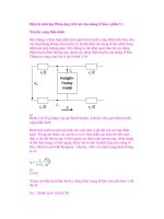
4.6.2 Light-Emitting Transistor
Researchers at the University of Illinois-Urbana/Champaign have created
a light-emitting transistor that could make the transistor the fundamental
element in optoelectronics as well as in electronics (Fig. 4-2).
94 THE FUTURE IS FIBER—OPTICAL TECHNOLOGIES
c4.qxd 8/30/04 2:39 PM Page 94
“We have demonstrated light emission from the base layer of a hetero-
junction bipolar transistor and showed that the light intensity can be con-
trolled by varying the base current,” says Nick Holonyak, a John Bardeen
professor of electrical and computer engineering and physics at the Univer-
sity of Illinois. Holonyak invented the first practical light-emitting diode and
the first semiconductor laser to operate in the visible spectrum. “This work is
still in the early stage, so it is not yet possible to say what all the applications
will be,” says Holonyak.“But a light-emitting transistor opens up a rich domain
of integrated circuitry and high-speed signal processing that involves both
electrical signals and optical signals.”
A transistor usually has two ports: one for input and one for output. “Our
new device has three ports: an input, an electrical output, and an optical
output,” says Milton Feng, professor of electrical and computer engineering at
Illinois. “This means that we can interconnect optical and electrical signals for
display or communication purposes.” Feng is credited with creating the world’s
fastest bipolar transistor, a device that operates at a frequency of 509 GHz.
Graduate student Walid Hafez fabricated the light-emitting transistor at the
University of Illinois’ micro and nanotechnology lab. Unlike traditional tran-
sistors, which are built from silicon and germanium, the light-emitting transis-
tors are made from indium gallium phosphide and gallium arsenide. “In a
LIGHT EMITTERS 95
Figure 4-2 Light-emitting transistor.
c4.qxd 8/30/04 2:39 PM Page 95
bipolar device, there are two kinds of injected carriers: negatively charged
electrons and positively charged holes,” Holonyak says. “Some of these car-
riers will recombine rapidly, supported by a base current that is essential for
the normal transistor function.”
The recombination process in indium gallium phosphide and gallium
arsenide materials also creates infrared photons, the “light” in the researchers’
light-emitting transistors. “In the past, this base current has been regarded as
a waste current that generates unwanted heat,” says Holonyak. “We’ve shown
that for a certain type of transistor, the base current creates light that can be
modulated at transistor speed.”
Although the recombination process is the same as that which occurs in
light-emitting diodes, the photons in light-emitting transistors are generated
under much higher speed conditions. So far, the researchers have demon-
strated the modulation of light emission in phase with a base current in tran-
sistors operating at a frequency of 1MHz. Much higher speeds are considered
certain.
“At such speeds, optical interconnects could replace electrical wiring
between electronic components on a circuit board,” says Feng.This work could
be the beginning of an era in which photons are directed around a chip in
much the same fashion as electrons have been maneuvered on conventional
chips.
“In retrospect, we could say the groundwork for this was laid more than 56
years ago with John Bardeen and Walter Brattain and their first germanium
transistor,” says Holonyak, who was Bardeen’s first graduate student.“But the
direct recombination involving a photon is weak in germanium materials, and
John and Walter just wouldn’t have seen the light—even if they had looked.
If John were alive and we showed him this device, he would have to have a
big grin.”
4.6.3 VCSEL
A VCSEL (pronounced “vixel”) is a tiny laser that emits a beam vertically
from a chip’s surface. PARC has developed the world’s most densely packed
VCSEL array, with independently addressable laser elements placed on a
linear pitch as small as 3mm.
Silicon CMOS-based driver-integrated circuits can be combined with the
laser array to form an ultradense optoelectronic multi-chip module using
PARC’s StressedMetal MEMS high-density interconnect technology. Such an
imager-on-a-chip allows thousands of independently addressable lasers to be
packaged in a compact module. The imagers could eliminate optical systems
with mechanical moving parts, replacing them with a more compact, all solid-
state light source.
VCSELs could be used for building optical interconnects that transfer data
between computers via lasers. One application would replace copper cables
96 THE FUTURE IS FIBER—OPTICAL TECHNOLOGIES
c4.qxd 8/30/04 2:39 PM Page 96
with bundles of optical fiber ribbons to connect electronic boards in computer
back-planes, enabling much faster data transfer rates.
4.6.4 Improved VCSEL
With optical communications becoming increasingly important to telecom
manufacturers, service providers, and users, scientists are pushing hard to
create better performing lasers that promise to increase distance, boost effi-
ciency, and reduce the cost of optical connections. At the University of Illinois
at Urbana-Champaign, researchers have found a way to significantly improve
the performance of VCSEL by drilling holes in their surfaces. Faster and
cheaper long-haul optical communication systems, as well as photonic inte-
grated circuits, could be the result.
Low-cost VCSELs are currently used in data communication applications
where beam quality is of little importance, such as in short fiber runs. To
operate at higher speeds and over longer distances, however, the devices must
function in a single transverse mode with a carefully controlled beam. “These
characteristics are normally found only in very expensive lasers, not in
mass-produced VCSELs,” says Kent D. Choquette, a professor of electrical
and computer engineering and a researcher at the university’s Micro and
Nanotechnology Laboratory. “By embedding a two-dimensional photonic
crystal into the top face of a VCSEL, however, we can accurately design and
control the device’s mode characteristics.”
The two-dimensional photonic crystal, created by drilling holes in the semi-
conductor surface, introduces a periodic change in the index of refraction,
Choquette says. The holes represent regions of low refractive index, sur-
rounded by semiconductor material where the index is higher. A particular
combination of refractive indices will produce a single-mode waveguide that
permits only one transverse wave of the laser beam to propagate. “Our pho-
tonic crystal consists of a triangular array of circular holes that have been
etched into the top of a VCSEL,” Choquette says. “Because the index varia-
tion has to be on the length scale of light, the periodicity of the holes must be
on the order of several hundred nanometers.”
To create such a precise array of holes, the researchers first lithographically
define the desired pattern into a silicon dioxide mask layer on the semicon-
ductor surface using focused-ion beam etching. Researchers then bore holes
into the semiconductor material using inductively coupled plasma etching.“By
selectively varying parameters such as depth, diameter, and spacing of the
holes, we can control the modal characteristics of the laser,” Choquette says.
“This means we can accurately design and fabricate single-mode VCSELs for
high-performance optical communication systems.”
The next step, he says, is to push VCSEL performance toward higher power
by considering designs that are much larger in diameter. “Looking beyond
that, we also have fundamental problems with high-speed data communica-
LIGHT EMITTERS 97
c4.qxd 8/30/04 2:39 PM Page 97
tion on our circuit boards and in our chips,” Choquette says. “This is a tech-
nology that could serve as the foundation for a new way of looking at optical
interconnects and photonic integrated circuits.”
4.6.5 Tiny Laser
Bell Labs researchers have built a tiny semiconductor laser that has the poten-
tial for advanced optical communication applications, including multiple
laser-on-a-chip applications. The device exploits a photonic crystal, a highly
engineered material with superior optical properties, and was made in collab-
oration with scientists from the New Jersey Nanotechnology Consortium,
California Institute of Technology, and Harvard University.
“This new laser was made possible by taking advances from many differ-
ent areas in physics and incorporating them into one device,” says Cherry
Murray, senior vice president of physical sciences research at Bell Labs. “This
work will open up new directions not only for optoelectronics and sensing but
could also provide a new tool to investigate very basic physical phenomena.”
The laser belongs to a class of high-performance semiconductor lasers,
known as quantum cascade (QC) lasers, which were invented at Bell Labs in
1994. QC lasers are made by stacking many ultrathin atomic layers of stan-
dard semiconductor materials (such as those used in photonics) on top of each
another, much like a club sandwich. By varying the thickness of the layers, it’s
possible to select the particular wavelength at which a QC laser will emit light,
allowing scientists to custom design a laser.
When an electric current flows through a QC laser, electrons cascade down
an energy “staircase,” and every time an electron hits a step, a photon of
infrared light is emitted. The emitted photons are reflected back and forth
inside the semiconductor resonator that contains the electronic cascade,
stimulating the emission of other photons. This amplification process enables
high-output power from a small device.
In the decade since their invention, QC lasers have proven to be very con-
venient light sources. Besides being powerful, they are compact, rugged, and
often portable. Yet the devices can’t emit light from its edges or through its
surface.
The Bell Labs team overcame this challenge by using the precise light-
controlling qualities of a photonic crystal to create a QC laser that emits
photons perpendicular to the semiconductor layers, resulting in a laser that
emits light through its surface. Photonic crystals are materials with repeating
patterns spaced very close to one another, with separations between the pat-
terns comparable to the wavelengths of light. When light falls on such a pat-
terned material, the photons of light interact with it; with proper design of the
patterns, it’s possible to control and manipulate the propagation of light within
the material.
Using a state-of-the-art electron beam lithography facility at the New Jersey
Nanotechnology Consortium, located at Bell Labs headquarters in Murray
98 THE FUTURE IS FIBER—OPTICAL TECHNOLOGIES
c4.qxd 8/30/04 2:39 PM Page 98
Hill, New Jersey, the researchers were able to superimpose a hexagonal pho-
tonic crystal pattern on the semiconductor layers that made the QC laser. The
final laser was only 50mm across or about half the diameter of a human hair.
“The most exciting part of this work is that we combined photonic and elec-
tronic engineering to create a new surface-emitting QC laser,” says Al Cho,
adjunct vice president of semiconductor research at Bell Labs and one of the
inventors of the QC laser. “The photonic crystal approach has real potential
for new applications. The production of surface-emitting compact lasers only
50 micrometers across enables large arrays of devices to be produced on a
single chip, each with its own designed emission properties.”
Such lasers-on-chips may lead to new possibilities for optical communica-
tions, as well as other optoelectronic and sensing technologies. QC lasers have
already been used to make extremely sensitive sensors, including sensors that
have been used by NASA for atmospheric monitoring.
“The next step is to see if we can use this sort of technique to get sensing
done within the laser,” says Federico Capasso, a Harvard University consult-
ant who is also a Bell Labs consultant and one of the inventors of the QC
laser. “If we can fill the holes of the photonic crystal in this laser with nano-
liters of fluid or other special material, we may get some interesting physics as
well as a whole new world of applications.”
4.6.6 Looking Into Lasers
University of Toronto researchers are looking to create more powerful and
efficient lasers for fiber-optic communication systems by looking inside lasers
while they are operating. “We’ve seen the inner workings of a laser in action,”
says investigator Ted Sargent, a professor in the university’s department of
electrical and computer engineering. “We’ve produced a topographical map
of the landscape that electrons see as they flow into these lasers to produce
light.” He says the findings could influence laser design, change the diagnosis
of faulty lasers, and potentially reduce manufacturing costs.
Lasers are created by growing a complex and carefully designed series of
nanometer-sized layers of crystals on a disk of semiconductor material known
as a wafer. Ridges are etched into the crystal surface to guide laser light, thin
metal layers are added on top and bottom, and the wafer is then cut into tiny
cubes or chips. During the laser’s operation, an electrical current flows into the
chip, providing the energy to generate intense light at a specific wavelength
used in fiber-optic communications.
The University of Toronto researchers focused their efforts on the “beating
heart” portion of the laser (called the active region), where electronic energy
is converted into light. Using a technique called scanning voltage microscopy,
they examined the surface of an operating laser, picking up differences in
voltage. These differences translate to a topographical image of the laser’s
energy surface, allowing researchers to visualize the forces an electron expe-
riences along its path into the active region, Sargent says.
LIGHT EMITTERS 99
c4.qxd 8/30/04 2:39 PM Page 99
The team used its newly acquired information about the inside operations
of the laser to determine the fraction of electric current that contributes to
producing light. The balance of electrons are undesirably diverted from the
active region: such current leakage wastes electrons and heats the device up,
degrading performance.“We used direct imaging to resolve a contentious issue
in the field: the effectiveness of electronic funneling into the active region of
a ridge-waveguide laser,” says Dayan Ban, a University of Toronto doctoral
candidate who made the measurements. “Previously, uncorroborated models
had fueled speculation by yielding divergent results. Now we know where the
electrons go.” Ban is now a researcher at the Institute for Microstructural
Sciences of the National Research Council of Canada.
“Direct imaging of the functions that drive the action of a living laser could
transform how we think about laser ‘diagnosis and therapy,’ ” says Sargent,
referring to the measurement and optimization of laser structures and their
determination of the devices’ inner workings. Designers now use a variety of
computer simulations to model how lasers work, but research at the Univer-
sity of Toronto may show which simulations are the most accurate design tools.
“With accurate models,” says Sargent, “the designs we can create are more
likely to result in devices that meet design requirements.”
The research could also help in diagnosing faulty lasers.“If a particular laser
fails, the kind of measurements that we are taking could provide some idea
of why it failed and the design could then be modified,” says St. John
Dixon-Warren, a project coinvestigator and a physical chemist at Bookham
Technology, an optical components manufacturer based in the United
Kingdom.
Sargent says the findings could have larger implications for the creation of
optical circuits for fiber-optic communications.“If we could fully develop these
models and fully understand how lasers work, then we could start to build
optical circuits with confidence and high probability of success,” he says.
“Optical chips akin to electronic integrated circuits in computers must be
founded on a deep and broad understanding of the processes at work inside
current and future generations of lasers.”
4.6.7 Manipulating Light
Manipulating light on the nanoscale level can be a Herculean task, since the
nanoscale level is so incredibly tiny—less than one-tenth the wavelength of
light. Researchers at Argonne National Laboratory are making strides toward
understanding and manipulating light at the nanoscale level by using the
unusual optical properties of metal nanoparticles, opening the door to micro-
scopic-sized devices such as optical circuits and switches.
Metal nanoparticles, such as extremely tiny spheres of silver or gold, can
concentrate large amounts of light energy at their surfaces. The light energy
confined near the surface is known as the near field, whereas ordinary light is
known as far field. Many scientists believe that, by understanding how to
100 THE FUTURE IS FIBER—OPTICAL TECHNOLOGIES
c4.qxd 8/30/04 2:39 PM Page 100
manipulate near-field light, new optical devices could be built at dimensions
far smaller than is currently possible. In an effort to characterize near-field
behavior, a joint experimental and theoretical study published in the Decem-
ber 25, 2003, issue of the Journal of Physical Chemistry B used powerful high-
resolution imaging and modeling techniques to detail how light is localized
and scattered by metal nanoparticles.
Technologies, such as high-speed computers and internet routers, rely
heavily on electrons flowing through wires to function. However,with the ever-
increasing demand for higher data rates and smaller sizes, the complexity of
electrical circuits becomes untenable. This challenge can be overcome by
replacing electrons with photons (units of light), since the wave-like character
of photons would reduce obstacles such as heat and friction within a given
system. “In a nutshell, photons move faster than electrons,” says experimental
team leader Gary Wiederrecht. “They are a highly efficient power source just
waiting to be harnessed.”
“Using experimental and theoretical approaches, we were able to observe
the interaction of light with the surfaces of the metal nanoparticles. We hope
that this study will lead to the creation of optical technologies that can manip-
ulate light with precision at nanoscale dimensions,” explains Stephen Gray,
lead theoretician of the Journal study.
To obtain a more comprehensive understanding of the near field, the
Argonne researchers used an advanced imaging technique known as near-field
scanning optical microscopy. The nanoparticles, with diameters as small as
25nm, were placed on a prism and illuminated with laser light, forming a near
field that was detectable with near-field scanning optical microscopy by a
nanoscale probe positioned close to the sample’s surface. Optical scattering
experiments were performed on isolated metal nanoparticles and arrays of
metal nanoparticles. Electron beam lithography was used to uniformly place
nanoparticles within 100nm from one another. Using a special experimental
setup, the team was able to explicitly map the near-field light intensity onto
the three-dimensional topography of the metal nanoparticle arrays.
Experimental results yielded a number of valuable findings regarding the
character of the near field. The researchers found that an isolated nanoparti-
cle would scatter light at a 20-degree angle from the prism surface. Further-
more, the researchers found that arrays of nanoparticles scatter light at much
smaller angles, an encouraging result for the use of near-field photons in two-
dimensional devices such as optical chips. All findings were validated by com-
putational and theoretical methods; together, there findings provide specific
information as to how near fields can be used to guide light.
4.7 OPTICAL ANTENNA
A new optical antenna, developed by researchers at the University of Warwick
in the United Kingdom, promises to bring significant benefits to wireless net-
OPTICAL ANTENNA 101
c4.qxd 8/30/04 2:39 PM Page 101
works, household electronics, and long-distance data transfers. The device
applies techniques used to manipulate radio frequencies to select the incom-
ing “signal frequencies” carried on infrared beams to produce the optical
equivalent of the radio.
The antenna, developed by Professor Roger Green and Roberto Ramirez-
Iniguez, in the University of Warwick’s engineering department, has been
licensed to Optical Antenna Solutions of Nottingham, United Kingdom, which
will be responsible for further development. Derick Wilson, Optical Antenna
Solutions’ managing director, believes the technology provides enormous
benefits to several industries and has significant commercial opportunities.
One of the first applications being considered is to use the antenna to provide
secure practical “point and pay methods” for credit cards.
An optical antenna serves the same purpose as an electronic one. It must
collect energy from an area and channel it through to a receiving element or,
conversely, transmit energy that has originated from a small source over an
area.The new device uses a combination of precise curvatures on the lens part
of the instrument with a multi-layered filter. The optical antenna is so precise
that it can detect a signal on one particular wavelength of light; it is also 100
times more efficient at gathering a signal than any previous optical sensor
of this kind. This has immediate benefits for indoor wireless networks and
household devices. It allows signal transmitters and receivers to operate at a
significant angle to each other and to discriminate much more finely between
signals. For external data transfer applications it can be used to greater dis-
tances—up to 3 miles.
Two major transmission technologies are presently used to achieve indoor
wireless communication: radio and infrared. For many reasons, infrared is
often preferred. Infrared links provide high bandwidth at low cost, infrared is
immune to radio interference, the spectrum is freely available, and infrared
components are inexpensive, small, and consume little power. The new optical
antenna could help turn even more people toward infrared as an alternative
to the high cost of maintaining wired networks.
4.8 KEEPING COPPER
With all of the ongoing research into optical technologies, it’s easy to forget
that old-fashioned copper wiring remains a perfectly suitable, and cheap,
technology for many telecommunication applications, particularly those that
involve short distances. Penn State University engineers have developed a
copper wire transmission scheme for distributing a broadband signal over local
area networks (LANs) with a lower average bit error rate than fiber optic
cable that is 10 times more expensive.
“Using copper wire is much cheaper than fiber-optic cable and, often, the
wire is already in place,” says Mohsen Kavehrad, a Penn State professor of
electrical engineering and director of the school’s Center for Information and
102 THE FUTURE IS FIBER—OPTICAL TECHNOLOGIES
c4.qxd 8/30/04 2:39 PM Page 102
Communications Technology Research.“Our approach can improve the capa-
bility of existing local area networks and shows that copper is a competitor
for new installations in the niche LAN market.”
The Penn State approach was developed in response to an IEEE challenge.
The organization wanted a signaling scheme for a next generation broadband
copper Ethernet network capable of carrying broadband signals of 10 gigabits
per second. Currently, the IEEE standard specifies 1 gigabit over 100 meters
of category 5 copper wire, which has four twisted pairs of wire in each
cable.
“In the existing copper gigabit systems, each pair of wires carries 250
megabits per second. For a 10-gigabit system, each pair will have to carry 2.5
gigabits per second,” says Kavehrad. “At these higher speeds, some energy
penetrates into the other wires and produces crosstalk.” The Penn State
scheme eliminates crosstalk by using a new error correction method that they
developed that jointly codes and decodes the signal and, in decoding, corrects
the errors.
“Conventional wisdom says you should deal with the wire pairs one pair at
a time, but we look at them jointly,” Kavehrad says. “We use the fact that we
know what signal is causing the crosstalk interference because it is the
strongest signal on one of the wires.” The Penn State approach also accounts
for the reduction or loss of signal energy between one end of the cable and
the other, which can become severe in 100-meter copper systems.
“We jointly code and decode the signals in an iterative fashion and, at the
same time, we equalize the signals,” Kavehrad says. “The new error correction
approach acts like a vacuum cleaner where you first go over the rough spots
and then go back again to pick up more particles.”
A simulation showed that the scheme is possible and can achieve an
average bit error rate of 10
-12
bits per second. Fiber-optic cable typically
achieves 10
-9
bits per second. The work is continuing.
KEEPING COPPER 103
c4.qxd 8/30/04 2:39 PM Page 103
Chapter 5
The Internet Rules—
IP Technologies
104
Telecosmos: The Next Great Telecom Revolution, edited by John Edwards
ISBN 0-471-65533-3 Copyright © 2005 by John Wiley & Sons, Inc.
It’s hard to believe that just 10 years ago only a select group of people (mostly
scientists and military leaders) was aware of the Internet. Today, it’s difficult
to imagine a world without Web surfing, e-mail, online chats, or (sad to say)
spam. Tomorrow’s Internet may still be plagued by spam in one form or
another (some miseries never seem to go away), but at least data will be faster
and more multimedia oriented.
5.1 VoIP TELEPHONY
Perhaps the biggest impact the Internet will have on telecom will come from
voice-over Internet protocol (VoIP) technology. Computer-based telephony is
a key technology that promises to supplement and perhaps even eventually
replace conventional telephones. VoIP technology has been around for several
years but has so far failed to live up to its potential. Still, a study by Parks
Associates, a technology research firm located in Dallas, Texas, finds that one-
half of all Internet households are interested in VoIP services, which could
deprive current long-distance companies of their most profitable subscribers.
Interest in these services is disproportionately high among subscribers with
oppressive monthly phone bills, with cost savings being the primary driver.
Furthermore, according to Parks’ research, interest in VoIP service is consis-
tent among both broadband (52 percent) and narrowband (48 percent) house-
c5.qxd 8/30/04 2:38 PM Page 104
holds. “Consumers are looking at VoIP service as a replacement for their
primary phone line, not as a secondary backup,” says John Barrett, a research
analyst at Parks. “VoIP could also serve as a lure for new broadband sub-
scribers, given the strong interest among narrowband households. The market
is still searching for a ‘killer’ broadband application. Wouldn’t it be ironic if it
turned out to be telephone service?”
Preconceived notions helped diminish VoIP’s consumer potential. “When
people think of consumer IP telephony, they often think of sound quality equal
to two cans tied together with string or as a dot.com fad,” says Daryl Schoolar,
a senior analyst with In-Stat/MDR, a technology research firm based in
Scottsdale, Arizona.
Still, although VoIP has been slow to gain traction with consumers, the tech-
nology is getting a second chance at life with enterprise adopters. In its enter-
prise incarnation, VoIP is experiencing solid growth. Probe Group, a telecom
research company located in Cedar Knolls, New Jersey, forecasts that
business-related IP voice services will experience geometric-level growth over
the next several years.“While some of this growth will be derived from gradual
increases in revenue per customer, the vast majority will come from rapid
growth in market penetration,” says Christine Hartman, a Probe analyst.
A combination of more widely dispersed organizations and shrinking
travel/relocation budgets will help grow the VoIP market. Improved software
and related technologies will also help boost the technology’s acceptance.
Additionally, vendors of hosted IP voice equipment have been refining and
improving the reliability of their products, leading to an array of reliable solu-
tions. Hosted solutions are particularly attractive in the present economic
climate because businesses are able to access advanced features without the
necessary investment in premise equipment.
Large carriers have addressed the market by providing managed services
directed toward major enterprise customers. Yet smaller carriers are also
developing hosted solutions, focusing on wholesale services and retail strate-
gies that concentrate on specific geographic areas. The combined worldwide
revenues for hosted VoIP services, including IP-PBX, videoconferencing,
contact center, and unified communications, are expected to grow from $46
million in 2001 to $36.5 billion in 2008, according to research from ABI, a tech-
nology research firm based in Oyster Bay, New York.
“In 2003, we saw continued growth from emerging services providers who,
after quietly launching their offers during 2001 and 2002, have been gradually
building their customer base,” says Julia Mermelstein, an ABI analyst. “While
these providers gain customer traction in focused vertical or geographic
markets, we will also see several incumbent telecom providers, who have been
slow to engage in the hosted VoIP services market, convert trial activities into
large-scale product launches.”
Enhanced technologies and growing enterprise interest in VoIP are also
renewing hope that the technology may finally achieve success in the consumer
market. The key to any future consumer growth will be the enhanced quality
VoIP TELEPHONY 105
c5.qxd 8/30/04 2:38 PM Page 105