AD HOC NETWORKS Technologies and Protocols phần 2 ppt
Bạn đang xem bản rút gọn của tài liệu. Xem và tải ngay bản đầy đủ của tài liệu tại đây (672.08 KB, 29 trang )
6
Ad Hoc Networks
in the overall wireless network classification? Most researchers will view ad
hoc wireless networks as a special subset of wireless networks. In fact, the ad
hoc radio technology and most of the MAC technology will be driven by the
advancements in infrastructure wireless networks. The unique design features
on ad hoc nets marking a departure from the former are in the network and
transport protocol areas (routing, multicast, ad hoc TCP and streaming, etc).
Another important family of ad hoc networks, the sensor networks, can in turn
be viewed as a subset of ad hoc networks. There are differences, however. At the
physical, MAC and network layers, the major innovations and unique features
of sensor nets (which set them apart from conventional ad hoc networks) are the
miniaturization, the embedding in the application contexts and the compliance
with extreme energy constraints. At the application layer, the most unique
and novel feature of sensor nets is undoubtedly the integration of transport and
in-network processing of the sensed data.
1.2
Ad Hoc Network Applications
Identifying the emerging commercial applications of the ad hoc network
technology has always been an elusive proposition at best. Of the three above
mentioned wireless technologies - cellular telephony, wireless Internet and ad
hoc networks - it is indeed the ad hoc network technology that has been the
slowest to materialize, at least in the commercial domain. This is quite surpris-
ing since the concept of ad hoc wireless networking was born in the early 70’s,
just months after the successful deployment of the Arpanet, when the military
discover the potential of wireless packet switching. Packet radio systems were
deployed much earlier than any cellular and wireless LAN technology. The
old folks may still remember that when Bob Metcalf (Xerox Park) came up
with the Ethernet in 1976, the word spread that this was one ingenious way to
demonstrate “packet radio” technology on a cable!
Why so slow a progress in the development and deployment of commercial
ad hoc applications? Main reason is that the original applications scenarios
were NOT directed to mass users. In fact, until recently, the driving applica-
tion was instant deployment in an unfriendly, remote infrastructure-less area.
Battlefield, Mars explorations, disaster recovery etc. have been an ideal match
for those features. Early DARPA packet radio scenarios were consistently fea-
turing dismounted soldiers, tanks and ambulances. A recent extension of the
battlefield is the homeland security scenario, where unmanned vehicles (UGVs
and UAVs) are rapidly deployed in urban areas hostile to man, say, to establish
communications before sending in the agents and medical emergency person-
nel.
Recently an important new concept has emerged which may help extend
ad hoc networking to commercial applications, namely, the concept of oppor-
Ad Hoc Network Applications
7
tunistic ad hoc networking
.
This new trend has been in part prompted by the
popularity of wireless telephony and wireless LANs, and the recognition that
these techniques have their limits. The ad hoc network is used “opportunis-
tically” to extend a home or Campus network to areas not easily reached by
the above; or, to tie together Internet islands when the infrastructure is cut into
pieces - by natural forces or terrorists for examples).
Another important area that has propelled the ad hoc concept is sensor nets
.
Sensor nets combine transport and processing and amplify the need for low
energy operation, low form factor and low cost - so, these are specialized ad
hoc solutions. Nevertheless, they represent a very important growing market.
In the sequel we elaborate on two applications, the battlefield and the the
urban and Campus grid
.
1.2.1
The Battlefield
In future battlefield operations, autonomous agents such as Unmanned Ground
Vehicles (UGVs) and Unmanned Airborne Vehicles (UAVs) will be projected
to the forefront for intelligence, surveillance, strike, enemy antiaircraft sup-
pression, damage assessment, search and rescue and other tactical operations.
The agents will be organized in clusters (teams) of small unmanned ground,
sea and airborne vehicles in order to launch complex missions that comprise
several such teams. Examples of missions include: coordinated aerial sweep
of vast urban/suburban areas to track suspects; search and rescue operations in
unfriendly areas (e.g., chemical spills, fires, etc), exploration of remote plan-
ets, reconnaissance of enemy field in the battle theater, etc. In those applica-
tions, many different types of Unmanned Vehicles (UVs) will be required, each
equipped with different sensor, video reconnaissance, communications support
and weapon functions. A UV team may be homogeneous (e.g., all sensor UVs)
or heterogeneous (i.e., weapon carrying UVs intermixed with reconnaissance
UVs etc). Moreover, some teams may be airborne, other ground, sea and pos-
sibly underwater based. As the mission evolves, teams are reconfigured and
individual UVs move from one team to another to meet dynamically changing
requirements. In fact, missions will be empowered with an increasing degree
of autonomy. For instance, multiple UV teams collectively will determine the
best way to sweep a mine field, or the best strategy to eliminate an air defense
system. The successful, distributed management of the mission will require
efficient, reliable, low latency communications within members of each team,
across teams and to a manned command post. In particular, future naval mis-
sions at sea or shore will require effective and intelligent utilization of real-time
information and sensory data to assess unpredictable situations, identify and
track hostile targets, make rapid decisions, and robustly influence, control, and
monitor various aspects of the theater of operation. Littoral missions are ex-
8
Ad Hoc Networks
pected to be highly dynamic and unpredictable. Communication interruption
and delay are likely, and active deception and jamming are anticipated.
The Office of Naval Research (ONR) is currently investigating efficient sys-
tem solutions to address the above problems. ONR envisions unmanned systems
of Intelligent, Autonomous Networked Agents (AINS) to have a profound in-
fluence on future naval operations allowing continuous forward yet unobtrusive
presence and the capability to influence events ashore as required. Unmanned
vehicles have proven to be valuable in gathering tactical intelligence by surveil-
lance of the battlefield. For example, UAVs such as Predator and Global Hawk
are rapidly becoming integral part of military surveillance and reconnaissance
operations. The goal is to expand the UAV operational capabilities to include
not only surveillance and reconnaissance, but also strike and support mission
(e.g., command, control, and communications in the battle space). This new
class of autonomous vehicles is foreseen as being intelligent, collaborative,
recoverable, and highly maneuverable in support of future naval operations.
In a complex and large scale system of unmanned agents, such as designed
to handle a battlefield scenario, a terrorist attack situation or a nuclear disaster,
there may be several missions going on simultaneously in the same theater. A
particular mission is “embedded” in a much larger “system of systems”. In such
a large scale scenario the wireless, ad hoc communications among the teams
are supported by a global network infrastructure (the “Internet in the sky”).
The global network is provisioned independently of the missions themselves,
but it can opportunistically use several of the missions’ assets (ground, sea or
airborne) to maintain multihop connectivity
Figure 1.1. Internet in the sky architecture designed as part of the ONR supported Minuteman
project at UCLA.
Ad Hoc Network Applications
9
The development of the Internet in the Sky hinges on three essential tech-
nologies:
Robust wireless connectivity and dynamic networking of autonomous
unmanned vehicles and agents.
1
2
Intelligent agents including: mobile codes, distributed databases and
libraries, robots, intelligent routers, control protocols, dynamic services,
semantic brokers, message-passing entities.
3
Decentralized hierarchical agent-based organization.
As Figure 1.1 illustrates, the autonomous agents have varying domains of
responsibility at different levels of the hierarchy. For example, clusters of
UAVs operating at low altitude (1K-20K feet) may perform combat missions
with a focus on target identification, combat support, and close-in weapons
deployment. Mid-altitude clusters (20-50K feet) could execute knowledge ac-
quisition, for example, surveillance and reconnaissance missions such as de-
tecting objects of interest, performing sensor fusion/integration, coordinating
low-altitude vehicle deployments, and medium-range weapons support. The
high altitude cluster(s) (50K-80K feet) provides the connectivity. At this layer,
the cluster(s) has a wide view of the theater and would be positioned to provide
maximum communications coverage and will support high-bandwidth robust
connectivity to command and control elements located over-the-horizon from
the littoral/targeted areas.
We use this example to focus on mission oriented communications and more
precisely on a particular aspect of it, team multicast
.
In team multicast the
multicast group does not consist of individual members, rather, of teams. For
example, a team may be a special task force that is part of a search and rescue
mission. The message then must be broadcast to the various teams that are part
of the multicast group, and, to all UVs within each team. For example, a weapon
carrying airborne UV may broadcast an image of the target (say, a poison gas
plant) to the reconnaissance and sensor teams in front of the formation, in
order to get a more precise fix on the location of the target. The sensor UV
team(s) that has acquired such information will return the precise location. As
another example, suppose N teams with chemical sensors are assessing the
“plume” of a chemical spill from different directions. It will be important for
each team to broadcast its findings step by step to the other teams using team
multicast. In general, team multicast will be common place in ad hoc networks
designed to support collective tasks, such as occur in emergency recovery or in
the battlefield.
10
Ad Hoc Networks
1.2.2
The Urban and Campus Grids: a case for
opportunistic ad hoc networking
In this section we describe two sample applications that illustrate the research
challenges and the potential power of ad hoc as opportunistic extension of the
wireless infrastructure.
Two emerging wireless network scenarios that will soon become part of
our daily routines are vehicle communications in an urban environment, and
Campus nomadic networking
.
These environments are ripe for benefiting
from the technologies discussed in this report. Today, cars connect to the
cellular system, mostly for telephony services. The emerging technologies
however, will soon stimulate an explosion of new applications. Within the car
,
short range wireless communications (e.g., PAN technology) will be used for
monitoring and controlling the vehicle’s mechanical components as well as for
connecting the driver’s headset to the cellular phone. Another set of innovative
applications stems from communications with other cars on the road. The
potential applications include road safety messages, coordinated navigation,
network video games, and other peer-to-peer interactions. These network needs
can be efficiently supported by an “opportunistic” multihop wireless network
among cars which spans the urban road grid and which extends to intercity
highways. This ad hoc network can alleviate the overload of the fixed wireless
infrastructures (3G and hotspot networks). It can also offer an emergency
backup in case of massive fixed infrastructure failure (e.g., terrorist attack, act
of war, natural or industrial disaster, etc). The coupling of car multihop network,
on-board PAN and cellular wireless infrastructure represents a good example
of hybrid wireless network aimed at cost savings, performance improvements
and enhanced resilience to failures. An example of such network is illustrated
in Figure 1.2.
In the above application the vehicle is a communications hub where the ex-
tensive resources of the fixed radio infrastructure and the highly mobile ad hoc
radio capabilities meet to provide the necessary services. New networking and
radio technologies are needed when operations occur in the “extreme” condi-
tions, namely, extreme mobility (radio and networking), strict delay attributes
for safety applications (networking and radio), flexible resource management
and reliability (adaptive networks), and extreme throughput (radios). Extremely
flexible radio implementations are needed to realize this goal. Moreover, cross
layer adaptation is necessary to explore the tradeoffs between transmission rate,
reliability, and error control in these environments and to allow the network to
gradually adapt as the channel and the application behaviors are better appraised
through measurements.
Another interesting scenario is the Campus, where the term “Campus” here
takes the more general meaning of a place where people congregate for various
Ad Hoc Network Applications
11
Figure 1.2. An example opportunistic ad hoc network.
cultural and social (possibly group) activities, thus including Amusement Park,
Industrial Campus, Shopping Mall, etc. On a typical Campus today wireless
LAN access points in shops, hallways, street crossings, etc., enable nomadic
access to the Internet from various portable devices (e.g., laptops, notebooks,
PDAs, etc.). However, not all areas of a Campus or Mall are covered by depart-
ment/shop wireless LANs. Thus, other wireless media (e.g., GPRS, 1xRTT,
3G) may become useful to fill the gaps. There is a clear opportunity for multi-
ple interfaces or agile radios that can automatically connect to the best available
service. The Campus will also be ideal environment where group networking
will emerge. For example, on a University Campus students will form small
workgroups to exchange files and to share presentations, results, etc. In an
Amusement Park groups of young visitors will interconnect to play network
games, etc. Their parents will network to exchange photo shots and video
clips. To satisfy this type of close range networking applications, Personal
Area Networks such as Bluetooth and IEEE 802.15 may be brought into the
picture. Finally, “opportunistic” ad hoc networking will become a cost-effective
alternative to extend the coverage of access points. Again, as already observed
in the vehicular network example, the above “extensions” of the basic infras-
tructure network model require exactly the technologies recommended in this
report, namely: multimode radios, cross layer interaction (to select the best
radio interface) and some form of hybrid networking.
These are just simple examples of networked, mobile applications drawn
from our everyday lives. There is a wealth of more sophisticated and demand-
ing applications (for example, in the areas of pervasive computing, sensor net-
12
Ad Hoc Networks
works, battlefield, civilian preparedness, disaster recovery, etc) that will soon
be enabled and spun off by the new radio and network technologies.
1.3
Design Challenges
As mentioned earlier, ad hoc networks pose a host of new research problems
with respect to conventional wireless infrastructure networks. This book in fact
addresses these challenges and each chapter is focused on a particular design
issue at one of the layers of the protocol stack. We will provide a review of the
chapters shortly. First, we wish to report on some design challenges that cut
across the layers and should be kept in mind while reading about specific layer
solutions in the other chapters. These are: cross layer interaction; mobility,
and; scalability.
1.3.1
Cross Layer Interaction
Cross Layer Interaction/Optimization is a loaded word today, with many dif-
ferent meanings. In ad hoc networks it is however a very appropriate way to
refer the fact that it is virtually impossible to design a “universal” protocol (rout-
ing, MAC, multicast, transport, etc) and expect that it will function correctly
and efficiently in all situations. In fact, pre-defined protocol layers a’ la Internet
work reasonably well in wired nets (e.g., routing, addressing, DNS etc work
for large and small.). For example, the physical and MAC layers of the wired
E-net are the uncontested reference for of all Internet designs. In contrast, in
the wireless LAN (the closest relative of the E-net), there is convergence not
to one, but to a family of standards, from 802.16 to 15 to 11, each standard
addressing different environments etc. Even within the 802.11 family a broad
range of versions have been defined, to address different needs.
In ad hoc network design the importance of tuning the network protocols to
the radios and the applications to the network protocols is even more critical,
given the extreme range of variability of the systems parameters. Clearly, the
routing scheme that works best for network of a dozen students roaming the
Campus may not be suitable for the urban grid with thousand of cars or the
battlefield with an extreme range of node speeds and capabilities. Even more
important is the concept that in these cases the MAC, routing and applications
must be jointly designed. Moreover, as some parameters (eg, radio propaga-
tion, hostile interference, traffic demands, etc) may dynamically change, the
protocols must be adaptively tuned. Proper tuning requires exchange of infor-
mation across layers. For example in a MIMO (Multi Input, Multi Output) radio
system the antenna and MAC parameters and possibly routes are dynamically
reconfigured based on the state of the channel, which is learned from periodic
channel measurements. Thus, interaction between radio channel and protocols
is mandatory to achieve an efficient operating point. Video adaptation is another
Design Challenges
13
example of cross layer interaction: the video rate stipulated at session initial-
ization cannot be maintained if channel conditions deteriorate. The proper rate
adjustment requires careful interplay of end to end probing (eg, RTCP) as well
measurements from channel and routing.
1.3.2
Mobility and Scaling
Mobility and reconfiguration is what uniquely distinguished ad hoc networks
from other networks. Thus, being able to cope with nodes in motion is an
essential requirement. Large scale is also common in ad hoc networks, as
battlefield and emergency recovery operations often involve thousands of nodes.
The two aspects - mobility and scale - are actually intertwined: anybody can
find a workable ad hoc routing solution, say, for 10 nodes, no matter how
fast they move; and anybody can find a workable (albeit inefficient) solution
(for routing, addressing, service discovery etc) for a completely static ad hoc
network with 10,000 of nodes, say (just consider the Internet)! The problems
arise when the 10,000 nodes move at various speeds, in various directions over
a heterogeneous terrain. In this case, a fixed routing hierarchy such as in the
Internet does not work. That is when you have to take out the “big guns” to
handle the problem.
Mobility is often viewed as the #1 enemy of the wireless ad hoc network
designer. However, mobility, if properly characterized, modeled, predicted
and taken into account, can be of tremendous help in the design of scaleable
protocols. In the sequel we offer a few examples where mobility actually helps.
1.3.2.1 An example: Team Communications among Airborne Agents
using LANMAR. LANMAR is a scalable routing protocol for large, mobile,
“flat” ad hoc wireless networks. It has been implemented in the Minuteman net-
work under ONR support [1]. LANMAR assumes that the network is grouped
into logical subnets in which the members have a commonality of interests and
are likely to move as a “group” (e.g., a team of co-workers at a convention; or
tanks in a battalion, or UAVs in an unmanned scouting mission). The logical
groups are efficiently reflected in the addressing scheme. We assume that a two
level, IP like MANET (Mobile Ad hoc NET) address is used consisting of a
group ID (or subnet ID) and a host ID, i.e. <Group ID, Host ID>. The group
ID tells us which nodes are part of the same group. Group assocoation may
change from time to time as a node is reassigned to a different group (e.g. task
force in a military scenario). The Host ID is fixed and typically corresponds
to the hardwired device address. Such MANET address uniquely identifies the
role (and position) of each node in the network. Similar to an IP network, the
packet is routed to the group first, and then to the Host within the group. The
challenge is to “find” the group in a large, mobile network.
14
Ad Hoc Networks
LANMAR uses the notion of landmarks to keep track of such logical groups.
Each logical group has one node serving as “landmark”. The landmark adver-
tises the route to itself by propagating a Distance Vector, e.g. DSDV (Destina-
tion Sequences Distance Vector) [3]. Further, the LANMAR routing scheme
is always combined with a local routing algorithm, e.g. Fisheye State Routing
(FSR) [2]. FSR is a link state routing algorithm with limited “scope” feature
for local, low overhead operation. Namely, FSR knows the routes to all nodes
within a predefined Fisheye scope (e.g., 3 hops) from the source. For nodes
outside of the Fisheye scope, the landmark distance vector must be inspected
for directions. As a result, each node has detailed topology information about
nodes within its Fisheye scope and knows distance and routing vector (i.e., di-
rection) to all landmarks. An example of LANMAR routing implementation is
shown in Figure 1.3.
Figure 1.3. An example of LANMAR implementation.
When a node needs to relay a packet to a destination that is within its Fisheye
scope, it obtains accurate routing information from the Fisheye Routing Tables.
The packet will be forwarded directly. Otherwise, the packet will be routed
towards the landmark corresponding to the destination logical subnet, which
is read from the logical address field in the MANET address. Thus, when the
packet arrives within the scope of the destination, it may be routed to it directly
without ever going through the landmark. In summary, the hierarchical LAN-
MAR setup does the scalability trick - it reduces routing table size and route
update overhead making the scheme practical for a network with practically
unlimited number of nodes (as long as nodes move in groups of increasing
size).The latter assumption is actually well validated in ad hoc networks asso-
ciated with large scale, cooperative operations (eg, battlefield). If nodes are
moving randomly and in a non coordinated fashion (like perhaps the customers
in a shopping mall) other techniques can be used to achieve scalability in a
random motion scenario. Along these lines, recently proposed routing and
Evaluating Ad Hoc Network Protocols - the Case for a Testbed
15
resource discovery schemes such as “last encounter routing”, and “epidemic
dissemination” exploit the fact that, with random motion, the destination that
I want to reach “has been seen” some time ago by some nodes that now have
moved close to me. This is a perfect example of symbiosis of mechanical in-
formation transport and electronic information relay. It allows me to find the
destination through a “motion assisted” search which eliminates the need for a
costly (and definitely non scalable) full search.
1.4
Evaluating Ad Hoc Network Protocols - the Case for a
Testbed
Analysis, simulation, hybrid simulation and testbed measurements are well
known techniques for evaluating ad hoc network protocols. At a time when
ad hoc network “standards” are being proposed in the MANET (Mobile Ad
Hoc Networks) working group of the IETF, it is clearly important to have a set
of reliable performance evaluation and measurement tools to compare various
proposals in a consistent environment that can be calibrated and replicated.
This is where the notion of “national” ad hoc network test-bed comes in the
picture. In this section we review the mission and goals of one such testbed,
the WHYNET NSF Testbed recently established in southern California with
the participation of various academic and industrial Campuses.
WHYNET is a wireless networking testbed that can be used to evaluate the
impact of emerging technologies that are going to shape the nature of wireless,
mobile communications in the next decade. The eventual impact of this research
testbed will be to redefine how specific innovations in wireless communication
technologies are evaluated in terms of their potential to improve application-
level performance as well as how alternative approaches are compared with
each other.
WHYNET differs from existing testbeds both in its scope and approach.
Its primary objective is to provide researchers at every layer of the protocol
stack, from physical devices to transport protocols, a testbed to evaluate the
impact of their technology on application level performance, using scalable
and realistic operational scenarios. To achieve this objective, WHYNET will
use a geographically-distributed, hybrid networking testbed that combines the
realism of physical testing with the scalability of multi-mode simulations.
The primary deliverable from WHYNET will be a set of tools and method-
ologies encapsulated in a well-defined evaluation framework, a set of studies
that demonstrate its suitability for evaluation of emerging network technolo-
gies, and a repository of networking scenarios, measurements, and models.
The design and development of the testbed will require coordinated efforts
of a multi-disciplinary, multi-institution team of researchers from academia,
government, and industry. This effort will substantially leverage existing net-
16
Ad Hoc Networks
working research funded by NSF, ONR, ARO, DARPA, and corporate sponsors
that include HP, Intel, Ericsson, Nokia, and Microsoft.
A central component of WHYNET will be its incorporation of geographi-
cally distributed physical testbeds. This will allow researchers to experiment
locally with physical prototypes, while providing a cost effective method to
support diverse operational environments in the testbed. The geographically-
distributed physical testbed will also be integrated into a scalable, multi-tool
simulation framework, which will allow investigators to evaluate the scalabil-
ity properties of innovative networking technologies. When fully deployed,
WHYNET will include a physical 3G CDMA testbed, a multiplicity of radio
platforms that include narrowband, broadband, and software defined radios, a
set of small to medium physical MANET testbeds incorporating novel radio de-
vices, a collection of measurements and models for a diverse set of antenna and
channel conditions, and a large set of reusable protocol models and application
scenarios. In addition, WHYNET will be used to perform a set of studies that
are expected to include the following:
Perceptual evaluation of networking protocols
CLI (Cross Layer Interaction) aware wireless networking
Comparative evaluation of new radio devices
Policy based routing with QoS assurance
Protocols and middleware services for mesh networking
Sensor networks
Energy-aware networks
Security in scalable ad hoc networks
Adaptive transport protocols
Although the primary purpose of these studies is to evaluate novel network-
ing technologies, they will also be used to demonstrate the unique contributions
of testbeds such as WHYNET in the design and evaluation of next generation
networking technologies. For instance, the studies on protocols for mesh net-
working will demonstrate WHYNET capabilities of supporting smooth transi-
tion from system design to deployment. Protocol prototypes can communicate
with simulated low layers for repeatable results, or obtain varying rate real
multimedia application traffic for perceptual evaluation. Once the physical
hardware devices are ready for testing, a portion of target network system can
be configured with real devices while the rest of the network can still reside in
the simulated hardware domain.
Overview of the Chapters in this Book
17
1.5
Overview of the Chapters in this Book
In this section we review the chapters of the book, commenting on their
specific contributions. In order to relate the contributions to the “big picture”,
we plan to illustrate their impact on a representative application. In sect 2.6 we
depicted the urban grid scenario which provided an excellent example of “op-
portunistic” ad hoc network. In fact, the urban grid network poses formidable
protocol design challenges, from the MAC layer all the way to applications.
This book will certainly offer invaluable help to anyone who plans to engage
in grid network design, and more generally, in ad hoc network research. To
illustrate the relevance of the concepts presented in these chapters, for each
chapter that is being reviewed, we will pose the question: How can this suite of
protocols help in the design of an urban vehicle grid? The proposed protocols
may not answer all the questions. The deal then is to discuss the additional
requirements in the Future Research section.
Chapter 2:
Collision Avoidance Protocols
This chapter provides an excellent overview of the CSMA/CA protocol along
with elegant analytic methods to evaluate the efficiency of the protocol in vari-
ous scenarios and for various parameters. An additional bonus of this chapter is
the discussion of fairness of the MAC layer under UDP (say, for video stream-
ing applications) as well as under TCP. Considering our strawman urban grid
application, accurate MAC layer modeling will be critical in the design of the
emerging vehicular MAC standards. In particular, it will be important that
whatever MAC standard is chosen, it perform well under TCP and streaming.
The material in this chapter will assist in that choice.
Chapter 3:
Routing in Ad Hoc Networks
This chapter describes various routing protocols that have been proposed
for ad hoc networks. Proactive (DSDV, OLSR, TBRPF), and reactive routing
protocols (DSR, AODV) and hybrid protocols (ZRP) are evaluated. Particu-
larly interesting is the discussion of geo-routing protocols and more generally,
location assisted routing protocols (GPSR, LAR, DREAM). In the urban grid
environment cars and pedestrians know their coordinates, thus they can rely on
the geographical routing assistance. Hybrid routing may also be considered, in
order not to get bogged down too often by the numerous obstacles. This chap-
ter provides the right information to tackle the routing design and evaluation
problem.
18
Ad Hoc Networks
Chapter 4:
Multicasting in Ad Hoc Networks
Multicast (both reliable data multicast and multimedia streaming) is a critical
service in MANETs where data and video must be broadcast to all users/teams
participating in the same mission (e.g., search and rescue operation). This
chapter does a thorough survey of the literature. It also brings up the challenge
of node mobility and network dynamic. The most popular multicast protocols
- MAODV, ODMRP - are first reviewed. Then, more specialized protocols
are introduced: MCEDAR (using the concepts of clustering and backbone),
AMRoute (relying on the overlay multicast concept), Geocast, Gossip (based on
random re-broadcast). Additional requirements may be placed on top of basic
multicast, for example: reliability, QoS, security. Considering our urban grid
model, it is easy to visualize the case where a squad of patrol cars, distributed
all over town, is engaged in a sweep operation, say looking for a suspect.
Any of the above schemes should be carefully evaluated for the urban grid
implementation. Naturally, if the multicast group member locations (either
GPS or urban grid coordinates) are known, the geocast option becomes very
attractive. If the operation is a covert operation, secure multicast is needed to
encrypt the contents and also to maintain motion secrecy.
Chapter 5:
Transport Layer Protocols in Ad Hoc Networks
TCP accounts for 90% of the traffic in the internet. This trend will be main-
tained in the a hoc network (unless one goes about a radical change of all the
applications). TCP is well known to degrade in mobile ad hoc networks. This
chapter analyses the causes of performance degradation. The most obvious
indication that something is going wrong is packet loss. However, the loss may
be due to congestion - in which case the TCP should slow down. Or it may be
caused by random errors, jamming, route breakup induced by motion. In the
latter cases, TCP must not slow down the flow, else matters get worse! One
well known problem is the inability to discriminate between congestion and
random loss. ELFN (Explicit Link Failure Notification) is a network feedback
technique that can be used to notify the TCP source of link failure (i.e., no con-
gestion!). The source then refreshes the path while freezing TCP. ATRA is a
more elaborate method that tries to minimize the effect of route failure by “pre-
dicting” and averting it using aggressive route recomputations. ATP requires
a complete redesign of the TCP protocol (using ATM style virtual circuit rate
control methods) to take advantage of selective feedback from specific nodes
along the path. Not clear how ATP will survive high mobility. In considering
the application of these options to the urban grid, one important requirement
is the compatibility of ad hoc TCP with the Internet TCP (since traffic may
originate or be directed to hosts in the Internet). This seems to rule out ATP
Overview of the Chapters in this Book
19
immediately since in ATP both source and destination TCP stacks are modified.
The remaining schemes are feasible and should be carefully evaluated.
Chapter 6:
Energy conservation
In ad hoc networks consisting of moving nodes (e.g. vehicles), energy con-
servation is generally not a critical issue. However, it clearly becomes a con-
cern in sensor networks or in ad hoc networks where the time to discharge a
“powered-on” node is less than the time between battery recharging opportu-
nities. This chapter provides an excellent survey of the various techniques to
conserve power, namely: power/topology control, energy routing, coordinated
sleep and power save management. If we go back to our urban grid example,
we note that cars have a practically unlimited reserve of energy. However,
pedestrians do not, especially if they use 802.11 in their PDAs. If the PDA has
multiple interfaces, say 802.11, ZigBee, cellular and Bluetooth, all the latter
options are more attractive as “always - on” options instead of 802.11. In fact,
radio interface selection could be yet another energy conservation strategy to
add to the above list. Another important component in the urban grid is the
environment sensor fabric. These sensors must interact with pedestrians and
cars (for example, a sensor field comes alive if a police car approaches). Thus,
sensors (and pedestrians) must be scheduled in such a way that their interaction
is most effective for a given recharge cycle. The schemes described in this
chapter are an excellent start for the investigation of suitable sensor/pedestrian
energy strategies,
Chapter 7:
Use of Smart Antennas in Ad Hoc Networks
Directive antennas are used for at least three reasons: extending range, fold-
ing jamming attacks and reducing the probability of detection. Smart antennas
add another feature - the ability to transmit simultaneously on multiple beams.
This chapter gives a brief overview of directional antennas. It then provides
an exhaustive survey of the interaction between antenna beamforming, MAC
protocols and routing protocols. It is in fact clear that, to take advantage of
antenna directionality, MAC and routing protocol changes are required. Are
smart antennas going to have an impact on our urban grid network strategy. Ab-
solutely! One can take advantage of the extended range of directional antennas
to establish backbone links along the major boulevards, say. Also, if UAVs are
used to assist in urban disaster recovery, directional antennas will do very well
for ground to air and air to air links. One important issue indirectly addressed
by this chapter is the coexistence of different MAC and routing protocols in the
same network, since only part of the nodes will be capable of antenna beaming.
In all, this chapter is an excellent start for an investigation of mixed antenna
strategies in complex environments such as urban grids and battlefields.
20
Ad Hoc Networks
Chapter 8:
QoS Issues in ad hoc networks
QoS support is critical in ad hoc networks since such networks either operate
as “opportunistic” extensions of the internet and thus carry Internet multimedia
traffic (VoIP, videocast, videoconference, etc); or, they operate in emergency
mode, and have even more stringent QoS requirements (delay, latency, jitter,
packet loss, etc)! This chapter does an excellent job in explaining the difference
between QoS guarantees in wired and in wireless ad hoc networks. It begins by
reviewing the methods for improving the performance of the 802.11 physical
layer (ARF, RBAR, OAR) and its impact on QoS. It then moves to the MAC layer
and shows how the 802.11b and 802.11e mechanisms (e.g., PCF schedule, IFS,
etc) can be manipulated to achieve DiffServ type PHB (Per Hop Behavior). This
is followed by a discussion of QoS routing which allows the source to enforce
Call Acceptance Control and/or service negotiation. INSIGNIA signaling could
be used for such negotiation. All this is body of information is very relevant to
our urban grid network. Suppose you want to watch a soccer game in your car.
Should you receive over the ad hoc car-net for free, or from UMTS and pay a
connection fee. The ad hoc network QoS mechanisms will tell your “intelligent”
mobile middleware which options are available, and for how long (if you buy
the predictive location based routing protocol described in this chapter!). After
you decide to use the ad hoc network (to save $$$ !!), the MAC and physical
layer parameters will be set to match your DiffServ DSCPs. Routing will abide
to its promise and find the route that fits your request.
Chapter 9:
Security in mobile Ad Hoc Networks
Ad hoc networks are much more vulnerable to security attacks than con-
ventional wired networks. The reasons: open wireless medium; capture of
unattended roaming nodes and impersonation; decentralized coordination pro-
tocols vulnerable to attack (e.g., contention based MAC); lack of centralized
certificate authority for key exchange; use of cache proxies that can be easily
hit by DDoS attacks, etc. This chapter reviews the various types of possible at-
tacks and discusses prevention measures. It introduces a MANET architecture
with Intrusion Detection System (IDS) agents located at monitoring nodes, and
dwells on the possible IDS agent cooperation strategies. This IDS technique is
then applied to detect of an attack to on demand routing (DSR or AODV) by
“anomaly” detection. In the context of our strawman urban grid scenario, the
protection from attacks is critical. MAC and routing attacks by a terrorist group,
for example, if successful, could impair the communications among the police
agents that try to apprehend them. Naturally, there are also “passive” attacks
we must protect from, for example position and motion privacy attacks. This
is an extremely important area, for which this chapter represents an excellent
introduction.
Conclusions
21
1.6
Conclusions
This book offers a solid background in ad hoc network protocols and tech-
nologies from which students and researchers can spring forward and attack
future challenges in the field. Among these future challenges for further prob-
ing we mention:
Wired and wireless interconnection: the 4G architecture will consist
of the interconnection of various wireless technologies with each other
and with the wired infrastructure. An important issue will be to inter-
connect ad hoc network islands with the wired network. For example,
the interconnection of ad hoc Campus networks via the Internet in such
a way that the ad hoc network users are unaware of the wired network.
Critical issues will be scalability, transparency and smooth handoff.
Backbone network: scalability is the major limitation to large scale
deployment of ad hoc networks. One way to solve the problem is to
use the existing infrastructure (eg, Internet, satellites, etc). If there is
no infrastructure, an important research direction is the use of mobile
backbone nodes.
Sensor integration with the ad hoc network: today, sensor networks
are developed and deployed with unique protocols and radio technologies
suitable for low energy operations and for the unique processing needs of
sensor nets - low energy, in-network processing, propagation of alarms to
collection centers. The information collected and processed by the sensor
fabric must often be relayed remotely to decision centers via an ad hoc
network. For example, in a heavily instrumented battlefield UAVs and
UGVs may be dispatched to extract information from the sensor fields
and make it available in the ad hoc network. This will require careful
coordination of sensor and network protocols. For example, content
based addressing instead of IP addressing will be the norm.
Exploiting mobility: node mobility if attacked in brute force mode can
be a serious obstacle to scalability, security and QoS support. However,
mobility can be exploited to make our job easier. The advantages of
accounting for group mobility were already exposed in sect 3.2.1 of this
chapter (LANMAR protocol). Other important benefits are in epidemic
diffusion of indices and “last encounter” routing. Motion prediction can
also assist in making georouting more efficient. Similarly, the presence
of high performance access points (eg, infostations or backbone nodes)
on a node’s trajectory may encourage to delay a data transfer instead of
transmitting the data immediately to low power neighbors.
1
2
3
4
22
Ad Hoc Networks
Motion privacy: security in wireless networks today mainly addresses
the protection of content and the defense from active attacks (internal or
external). An insidious passive attack that has mostly passed unnoticed
is the location and motion privacy attack. A mobile node may not wish
others to track its location or motion. Yet, the mere use of the most
popular routing protocols (e.g., AODV, OLSR, DSR etc) can easily give
away all the position and motion information to a “passive” intruder
which (being passive) will never be caught! This is particularly critical
for covert operations in the battlefield or in urban emergencies. The key
to protection is to embed security in our MANET protocols directly.
5
The above is just a small sample of the problems that lie ahead and await you
after you muster the content of this book. Enjoy the reading and be prepared
for ever greater challenges.
References
M. Gerla, X. Hong, and G. Pei. Landmark routing for large ad hoc wireless
networks. Proceeding of IEEE GLOBECOM 2000, Nov. 2000.
G. Pei, M. Gerla, and T. W. Chen. Fisheye state routing in mobile ad hoc
networks. Proceeding of ICDCS 2000 workshops, Apr. 2000.
C. Perkins and P. Bhagwat. Highly dynamic destination-sequenced
distance-vector routing (DSDV) for mobile computers.
Proceeding of the
ACM SIGCOMM’94, Sep. 1994.
[1]
[2]
[3]
Chapter 2
COLLISION AVOIDANCE PROTOCOLS
IN AD HOC NETWORKS
*
J. J. Garcia-Luna-Aceves
Department of Computer Engineering
University of California at Santa Cruz
Santa Cruz, CA 95064, U.S.A.
Yu Wang
Department of Computer Engineering
University of California at Santa Cruz
Santa Cruz, CA 95064, U.S.A.
We present an analytical model for the saturation throughput of sender-initiated
collision avoidance protocols in multi-hop ad hoc networks with nodes randomly
placed according to a two-dimensional Poisson distribution. We show that these
protocols can accommodate much fewer competing nodes within a region in a
network infested with hidden terminals than in those cases without hidden termi-
nals or with just a few. These results are validated through computer simulations.
We then introduce a framework to address the fairness problem inherent in ad hoc
networks using IEEE 802.11 and propose a topology-aware fair access (TAFA)
scheme to realize the framework. Simulation results show that TAFA can solve
the fairness problem in UDP-based applications with negligible degradation in
throughput, and the notorious problem of the starvation of flows in TCP-based
applications while incurring only some throughput degradation.
Collision avoidance, medium access control, ad hoc networks, fairness, IEEE
802.11, sender-initiated
Abstract
Keywords:
*This work was supported in part by the Defense Advanced Research Projects Agency (DARPA) under
Grant No. DAAD19-01-C-0026, the US Air Force/OSR under Grant No. F49620-00-1-0330 and the Jack
Baskin Chair of Computer Engineering at UCSC.
24
Collision Avoidance Protocols
Introduction
Wireless ad hoc networks have received increasing interest in recent years,
because of their potential to be used in a variety of applications without the aid
of any pre-existing network infrastructure.
Due to the scarce channel bandwidth available in ad hoc networks, the design
of efficient and effective medium access control (MAC) protocols that regulate
nodes’ access to a shared channel has become the subject of active research in
recent years.
Many MAC protocols [1] [2] [3] [4] [5] have been proposed to
mitigate the adverse effects of hidden terminals [6] through collision avoidance.
Most collision avoidance schemes such as the carrier sense multiple access with
collision avoidance (CSMA/CA) in the popular MAC protocols,IEEE 802.11
MAC protocol [2] are sender-initiated, including an exchange of short request-
to-send (RTS) and clear-to-send (CTS) packets between a pair of sending and
receiving nodes before the transmissions of the actual data packet and the op-
tional acknowledgment packet.
In Section 2.1, we present an analytical modeling [7] to derive the saturation
throughput of these sender-initiated collision avoidance protocols in multi-hop
ad hoc networks with nodes randomly placed according to a two-dimensional
Poisson distribution. We show that the sender-initiated collision-avoidance
scheme achieves much higher throughput than the ideal carrier sense multiple
access scheme with a separate channel for acknowledgments. More impor-
tantly, we show that the collision-avoidance scheme can accommodate much
fewer competing nodes within a region in a network infested with hidden ter-
minals than in a fully-connected network, if reasonable throughput is to be
maintained. Simulations of the IEEE 802.11 MAC protocol and one of its
variants validate the predictions made in the analysis.
The simulation results also reveal the fairness problem in IEEE 802.11 MAC
protocol which refers to the severe throughput degradation of some nodes due
to their unfavorable locations in the network and the commonly used binary
exponential backoff (BEB) algorithm which always favors the node that last
succeeds. This motivates the work presented in Section 2.2 in which we in-
troduce a framework to address the fairness problem conclusively and propose
a topology aware fair access (TAFA) scheme to realize the framework. Sim-
ulation results show that TAFA can solve the fairness problem in UDP-based
applications with negligible degradation in throughput. It can also solve the
notorious problem of the starvation of flows in TCP-based applications, while
incurring only some throughput degradation. Hence, TAFA shows a much better
overall tradeoff between throughput and fairness than other schemes previously
proposed.
Section 2.3 concludes this chapter with directions for future work.
Performance of collision avoidance protocols
25
2.1
Performance of collision avoidance protocols
In Section 2.1.1, we present the analysis of the sender-initiated collision-
avoidance scheme based on a four-way handshake and non-persistent carrier
sensing, which can be also called the RTS/CTS-based scheme for the sake of
simplicity. We first adopt a simple model in which nodes are randomly placed
on a plane according to two-dimensional Poisson distribution with density
Varying has the effect of changing the congestion level within a region as
well as the number of hidden terminals. In this model, it is also assumed that
each node is ready to transmit independently in each time slot with probability
where is a protocol-dependent parameter. This model was first used by
Takagi and Kleinrock [8] to derive the optimum transmission range of a node in a
multi-hop wireless network, and was used subsequently by Wu and Varshney [9]
to derive the throughputs of non-persistent CSMA and some variants of busy
tone multiple access (BTMA) protocols [6]. Then we assume that both carrier
sensing and collision avoidance work perfectly, that is, that nodes can accurately
sense the channel busy or idle, and that the RTS/CTS scheme can avoid the
transmission of data packets that collide with other packets at the receivers.
The latter assumption can be called perfect collision avoidance and has been
shown to be doable in the floor acquisition multiple access (FAMA) protocol [3].
Later we extend this model to take into account the possibility of data packets
colliding with other transmissions, so that the model is also applicable to other
MAC protocols, such as the popular IEEE 802.11 protocol, in which perfect
collision avoidance is not strictly enforced.
In Section 2.1.2, we present numerical results from our analysis. We com-
pare the performance of the sender-initiated collision avoidance scheme against
the idealized non-persistent CSMA protocol in which a secondary channel is
assumed to send acknowledgments in zero time and without collisions [6, 9],
as the latter is the only protocol whose analysis for multi-hop ad hoc networks
is available for comparison to date. It is shown that the RTS/CTS scheme can
achieve far better throughput than the CSMA protocol, even when the overhead
due to RTS/CTS exchange is high. The results illustrate the importance of
enforcing collision avoidance in the RTS/CTS handshake.
However, the analytical results also indicate that the aggregate throughput of
sender-initiated collision avoidance drops faster than that in a fully-connected
network when the number of competing nodes within a region increases. This
contrasts with conclusions drawn from the analysis of collision avoidance in
fully-connected networks or networks with limited hidden terminals [3]. Our
results show that hidden terminals degrade the performance of collision avoid-
ance protocols beyond the basic effect of having a longer vulnerability period
for RTSs. Hence, it follows that collision avoidance becomes more and more
ineffective for a relatively crowded region with hidden terminals.
26
Collision Avoidance Protocols
To validate the findings drawn from this analysis, in Section 2.1.3 we present
simulations of the popular IEEE 802.11 MAC protocol. The simulation results
clearly show that the IEEE 802.11 MAC protocol cannot ensure collision-free
transmission of data packets, and that almost half of the data packets transmitted
cannot be acknowledged due to collisions, even when the number of compet-
ing nodes in a neighborhood is only eight! However, the performance of the
simulated IEEE 802.11 MAC protocol correlates well with what is predicted
in the extended analysis, which takes into account the effect of data packet
collisions and is used for the case when the number of competing nodes in a
region is small. When the number of competing nodes in a region increases,
the performance gap between IEEE 802.11 and the analysis decreases, which
validates the statement that even a perfect collision-avoidance protocol loses its
effectiveness gradually due to the random nature of the channel access and the
limited information available to competing nodes.
The simulation results for the IEEE 802.11 protocol also show a larger vari-
ation in throughput than the predicted performance from the analytical model,
which is due to its inherent fairness problems which motivates the second part
of the work reported in this chapter.
2.1.1
Approximate Analysis
In this section, we derive the approximate throughput of a perfect collision
avoidance protocol. In our network model, nodes are two-dimensionally Pois-
son distributed over a plane with density i.e., the probability of finding
nodes in an area of S is given by:
Assume that each node has the same transmission and receiving range of R,
and denote by N the average number of nodes within a circular region of radius
R; therefore, we have
To simplify our analysis, we assume that nodes operate in time-slotted mode.
As prior results for CSMA and collision-avoidance protocols show [6], the
performance of MAC protocols based on carrier sensing is much the same as
the performance of their time-slotted counterparts in which the length of a time
slot equals one propagation delay and the propagation delay is much smaller
than the transmission time of data packets.
The length of each time slot is denoted by Note that is not just the
propagation delay, because it also includes the overhead due to the transmit-to-
receive turn-around time, carrier sensing delay and processing time. In effect,
represents the time required for all the nodes within the transmission range of
a node to know the event that occurred seconds ago. The transmission times
of RTS, CTS, data, and ACK packets are normalized with regard to and are
Performance of collision avoidance protocols
27
denoted by and respectively. Thus‚ is also equivalent to
1 in later derivations. For the sake of simplicity‚ we also assume that all packet
transmission times are multiples of the length of a time-slot.
We derive the protocol’s throughput based on the heavy-traffic assumption‚
i.e.‚ a node always has a packet in its buffer to be sent and the destination is
chosen randomly from one of its neighbors. This is a fair assumption in ad hoc
networks in which nodes are sending data and signaling packets continually.
We also assume that a node is ready to transmit with probability and not
ready with probability Here is a protocol-specific parameter that is slot
independent. At the level of individual nodes‚ the probability of being ready to
transmit may vary from time slot to slot‚ depending on the current states of both
the channel and the node. However‚ because we are interested in deriving the
average performance metrics instead of instantaneous or short-term metrics‚ the
assumption of a fixed probability may be considered as an averaged quantity
that can still reasonably approximate the factual burstiness from a long-term
point of view. In fact‚ this assumption is necessary to make the theoretical
modeling tractable and has been extensively applied before [10] [8] [9]. For
example‚ this model was used by Takagi and Kleinrock [8] to derive the optimal
transmission range of a node in a multi-hop wireless network‚ and was used
subsequently by Wu and Varshney [9] to derive the throughput of non-persistent
CSMA and some variants of busy tone multiple access (BTMA) protocols [6].
It should also be noted that‚ even when a node is ready to transmit‚ it may
transmit or not in the slot‚ depending on the collision avoidance and resolu-
tion schemes being used‚ as well as the channel’s current state. Thus‚ we are
more interested in the probability that a node transmits in a time slot‚ which is
denoted by Similar to the reasoning presented for we also assume that
is independent at any time slot to make the analysis tractable. Given this
simplification‚ can be defined to be
where is the limiting probability that the channel is in idle state‚ which we
derive subsequently.
We are not interested in the exact relationship between and and it is
enough to obtain the range of values that can take‚ because the throughput
of these protocols is mostly influenced by To derive the rough relationship
between and we set up a channel model that includes two key simplifying
assumptions.
First‚ we model the channel as a circular region in which there are some
nodes. The nodes within the region can communicate with each other while
they have weak interactions with nodes outside the region. Weak interaction
means that the decision of inner nodes to transmit‚ defer and back off is almost
28
Collision Avoidance Protocols
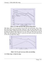
Figure 2.1. Markov chain model for the channel around a node
not affected by that of outer nodes and vice versa. Considering that nodes do
not exchange status information explicitly (e.g.‚ either defer due to collision
avoidance or back off due to collision resolution)‚ this assumption is reasonable
and helps to simplify the model considerably. Thus‚ the channel’s status is only
decided by the successful and failed transmissions within the region.
Second‚ we still consider the failed handshakes initiated by nodes within
the region to outside nodes‚ because this has a direct effect on the channel’s
usability for other nodes within the region. Though the radius of the circular
region is unknown‚ it falls between R/
2
and
2
R. This follows from noting
that the maximal radius of a circular region in which all nodes are guaranteed
to hear one another equals and all the direct neighbors and hidden
nodes are included into the region when Thus‚ we obtain
where and needs to be estimated.
With the above assumptions‚ the channel can be modeled by a four-state
Markov chain illustrated in Figure 2.1. The significance of the states of this
Markov chain is the following:
Idle is the state when the channel around node is sensed idle‚ and
obviously its duration is
Long is the state when a successful four-way handshake is done. For
simplicity‚ we assume that the channel is in effect busy for the duration
of the whole handshake‚ thus the busy time is
Short1 is the state when multiple nodes around the channel transmit RTS
packets during the same time slot and their transmissions collide. The
busy time of the channel is therefore
Performance of collision avoidance protocols
29
Short2 is the state when one node around the channel initiates a failed
handshake with a node outside the region. Even though a CTS packet
may not be sent due to the collision of the sending node’s RTS packet
with other packets originated from nodes outside the region or due to the
deferring of the receiving node to other nodes‚ those nodes overhearing
the RTS as well as the sending node do not know if the handshake is
successfully continued‚ until the time required for receiving a CTS packet
elapses. Therefore the channel is in effect busy‚ i.e.‚ unusable for all the
nodes sharing the channel‚ for the time stated below:
Now we proceed to calculate the transition probabilities of the Markov chain.
In most collision avoidance schemes with non-persistent carrier sensing‚ no
node is allowed to transmit immediately after the channel becomes idle‚ thus the
transition probabilities from long to idle‚ from short1 to idle and from short2
to idle are all 1.
According to the Poisson distribution of the nodes‚ the probability of having
nodes within the receiving range R of is where
Therefore‚ the mean number of nodes that belong to the shared channel is
Assuming that each node transmits independently‚
the probability that none of them transmits is where is the
probability that a node does not transmit in a time slot. Because the transition
probability from idle to idle is the probability that none of the neighboring
nodes of transmits in this slot‚ is given by
We average the probabilities over the number of interfering nodes in a region
because of two reasons. First‚ it is much more tractable than the approach that
conditions on the number of nodes‚ calculates the desired quantities‚ and then
uses the Poisson distribution to obtain the average. Second‚ in our simulation
experiments‚ we fix the number of competing nodes in a region (which is N)
and then vary the location of the nodes to approximate the Poisson distribution‚
which is configurationally closer to our analytical model; the alternative would
be to generate 2‚ 3‚ 4‚ nodes within one region‚ get the throughput for the
individual configuration and then calculate the average‚ which is not practical.
Next we need to calculate the transition probability from idle to long.
If there are nodes around node for such a transition to happen‚ one and
30
Collision Avoidance Protocols
only one node should be able to complete one successful four-way handshake
while other nodes do not transmit. Let denote the probability that a node
begins a successful four-way handshake at each slot‚ we can then calculate
as follows:
To obtain the above result‚ we use the fact that the distribution of the number
of nodes within does not depend on the existence of node because of the
memoryless property of the Poisson distribution. Up to this point‚ is still an
unknown quantity that we derive subsequently.
The transition probability from idle to short1 is the probability that more
than one node transmit RTS packets in the same slot; therefore‚ can be
calculated as follows:
Having calculated and we can calculate the transition
probability from idle to short2
Let and denote the steady-state probabilities of states idle‚ long‚
short1 and short2‚ respectively. From Figure 2.1‚ we have