all in one cisco ccie lab study guide second edition phần 4 doc
Bạn đang xem bản rút gọn của tài liệu. Xem và tải ngay bản đầy đủ của tài liệu tại đây (650.62 KB, 89 trang )
Add the service timestamps command to RouterA's configuration.
RouterA(config)#service timestamps
1.
On RouterA, monitor the routing table changes with the debug ip route command.
RouterA#debug ip routing
2.
Disconnect the serial line between RouterB and RouterC.3.
The following is the output from the debug command. Note that after the route was declared invalid, it was
placed in holddown, and approximately 30 seconds later, the route was cleared from the table.
07:03:18: RT: delete route to 152.1.0.0 via 192.1.1.2, rip metric
[120/2] ← Route is declared invalid
07:03:18: RT: no routes to 152.1.0.0, entering holddown ← Route is placed in holddown
07:03:18: 193.1.1.0 in 16 hops (inaccessible)
07:03:18: RT: delete route to 193.1.1.0 via 192.1.1.2, rip metric [120/1]
07:03:18: RT: no routes to 193.1.1.0, entering holddown
07:03:45: RT: garbage collecting entry for 152.1.0.0 ← Route is removed from
the routing table
07:03:45: RT: garbage collecting entry for 193.1.1.0
The following is the snapshot of the routing table after the route was declared invalid, but before the route was
flushed from the table. At this time, the route is marked down and advertised out to all neighbors with a hop
count of 16. After the route is flushed from the table, it is no longer advertised to neighboring routers.
RouterA#sho ip route
Codes: C − connected, S − static, I − IGRP, R − RIP, M − mobile, B − BGP
D − EIGRP, EX − EIGRP external, O − OSPF, IA − OSPF inter area
N1 − OSPF NSSA external type 1, N2 − OSPF NSSA external type 2
E1 − OSPF external type 1, E2 − OSPF external type 2, E − EGP
i − IS−IS, L1 − IS−IS level−1, L2 − IS−IS level−2, * − candidate default
U − per−user static route, o − ODR
Gateway of last resort is not set
10.0.0.0/24 is subnetted, 1 subnets
C 10.1.1.0 is directly connected, Loopback0
148.1.0.0/24 is subnetted, 1 subnets
C 148.1.1.0 is directly connected, Ethernet0
R 152.1.0.0/16 is possibly down, routing via 192.1.1.2, Serial0
C 192.1.1.0/24 is directly connected, Serial0
R 193.1.1.0/24 is possibly down, routing via 192.1.1.2, Serial0
The following is the output from the debug ip rip command taken during the transition from the invalid to
holddown to flushed state:
07:03:18: RIP: received v1 update from 192.1.1.2 on Serial0
07:03:18: 152.1.0.0 in 16 hops (inaccessible)
07:03:18: RIP: sending v1 update to 255.255.255.255 via Ethernet0 (148.1.1.1)
07:03:18: network 10.0.0.0, metric 1
07:03:18: network 152.1.0.0, metric 16
07:03:18: network 192.1.1.0, metric 1
07:03:45: RIP: sending v1 update to 255.255.255.255 via Ethernet0 (148.1.1.1)
07:03:45: network 10.0.0.0, metric 1
07:03:45: network 192.1.1.0, metric 1
Let's examine the data in chronological order using the timestamps. At 07:03:18, the route is declared invalid
and the holddown counter begins. At this time, the route is advertised to all neighbors during the normal
update period with a metric of 16. At 07:03:45, approximately 30 seconds after the route was declared invalid,
the route is removed from the routing table and is no longer advertised in the normal routing updates.
240
Lab #26: Configuring Unicast RIP Updates
Equipment Needed
The following equipment is needed to perform this lab exercise:
One Cisco router with one Ethernet port•
Cisco IOS 10.0 or higher•
A PC running a terminal emulation program•
One Cisco rolled cable•
The RIP neighbor command permits the point−to−point (nonbroadcast) exchange of routing information. This
command can be used in combination with the passive−interface router configuration command to exchange
information between a subset of routers and access servers all connected to the same LAN.
For example, in Figure 6−10, RouterA wishes to only send routing updates to RouterB on the Ethernet LAN.
Since RIP is a broadcast protocol, by default, it will send updates to all devices on the Ethernet LAN. To
prevent this from happening, RouterA's Ethernet interface is configured as passive. However, in this case, a
neighbor router configuration command is included. This command permits the sending of routing updates to
a specific neighbor. One copy of the routing update is generated per defined neighbor.
Figure 6−10: RIP Unicast updates
Router Configurations
The configuration for RouterA is as follows (key RIP configurations for RouterA are highlighted in bold).
RouterA
Building configuration
Current configuration:
!
version 11.2
no service password−encryption
no service udp−small−servers
no service tcp−small−servers
!
hostname RouterA
!
interface Loopback0
ip address 1.1.1.1 255.255.255.0
!
interface Ethernet0
ip address 192.1.1.1 255.255.255.0
no keepalive ← Disables the keepalive on the Ethernet interface, allows the
interface to stay up when it is not attached to a hub
!
!
router rip ← Enables the RIP routing process on the router
passive−interface Ethernet0 ← Disables the sending of RIP updates on interface
241
Ethernet 0
network 192.1.1.0 ← Specifies what interfaces will receive and send RIP routing
updates. It also specifies what networks will be advertised
network 1.1.1.1
neighbor 192.1.1.2 ← Permits the point−to−point (nonbroadcast) exchange of
routing information
!
no ip classless
!
line con 0
line aux 0
line vty 0 4
login
!
end
Monitoring and Testing the Configuration
The following is the output from the debug ip rip command. Note that RIP updates are being sent to the
Unicast address 192.1.1.2 on Ethernet 0 and the broadcast address 255.255.255.255 on interface loopback 0.
RouterA#debug ip rip
RIP: sending v1 update to 255.255.255.255 via Loopback0 (1.1.1.1)
network 192.1.1.0, metric 1
RIP: sending v1 update to 192.1.1.2 via Ethernet0 (192.1.1.1)
network 1.0.0.0, metric 1
Lab #27: RIP and Discontiguous Networks
Equipment Needed
The following equipment is needed to perform this lab exercise:
Two Cisco routers with one Ethernet port and one serial port•
Cisco IOS 10.0 or higher•
A PC running a terminal emulation program•
One Cisco rolled cable•
A discontiguous network is a network that has subnets of the same major network separated by another major
network. For example, in Figure 6−11, network 130.1.1.0/24 on RouterA is separated from network
130.1.2.0/24 on RouterB by the major network 131.1.1.0.
Figure 6−11: Discontiguous networks
Due to the classful nature of RIP and the fact that no mask information is carried in the routing updates,
support for discontiguous networks becomes a problem. For example, in Figure 6−11, when the RouterA
sends updates for network 130.1.1.0 to RouterB, it summarizes the network at the natural class — in this case,
class B (130.1.0.0). When RouterB receives an updated advertising network 130.1.0.0, it drops the update
because one of its own interfaces is connected to network 130.1.0.0. The router will not accept an update for a
network to which its own interface is connected.
The solution to this problem is to add a secondary address to the interfaces connecting RouterA to RouterB.
The secondary address should be in the same major network as the discontiguous network and use the same
242
subnet mask. As shown in Figure 6−12, with the addition of the secondary address, the networks are no longer
discontiguous.
Figure 6−12: Secondary address is used to support discontiguous networks
This configuration will demonstrate the use of secondary addresses to eliminate discontiguous networks
across a RIP network. RouterA and RouterB are connected serially via a crossover cable. RouterA will act as
the DCE supplying clock to RouterB. The IP addresses are assigned as per Figure 6−11. All routers will be
configured for RIP and advertise all connected networks.
Router Configurations
The configuration for RouterA is as follows (key RIP configurations are highlighted in bold).
RouterA
Current configuration:
!
version 12.0
service timestamps debug uptime
service timestamps log uptime
no service password−encryption
!
hostname RouterA
!
ip subnet−zero
!
interface Ethernet0/0
ip address 130.1.1.1 255.255.255.0
no ip directed−broadcast
no keepalive ← Disables the keepalive on the Ethernet interface, allows the
interface to stay up when it is not attached to a hub
!
interface Serial0/0
ip address 131.1.1.1 255.255.255.0
no ip directed−broadcast
no ip mroute−cache
clockrate 1000000 ← Acts as DCE providing clock
!
router rip ← Enables the RIP routing process on the router
network 130.1.0.0
network 131.1.0.0 ← Specifies what interfaces will receive and send RIP
routing updates. It also specifies what networks will be
advertised
!
ip classless
no ip http server
!
line con 0
transport input none
line aux 0
line vty 0 4
!
RouterB
Current configuration:
!
243
version 12.0
service timestamps debug uptime
service timestamps log uptime
no service password−encryption
!
hostname RouterB
!
ip subnet−zero
!
interface Ethernet0/0
ip address 130.1.2.1 255.255.255.0
no ip directed−broadcast
no keepalive ← Disables the keepalive on the Ethernet interface, allows the
interface to stay up when it is not attached to a hub
!
interface Serial0/0
ip address 131.1.1.2 255.255.255.0
no ip directed−broadcast
no ip mroute−cache
no fair−queue
!
router rip ← Enables the RIP routing process on the router
network 130.1.0.0
network 131.1.0.0 ← Specifies what interfaces will receive and send RIP
routing updates. It also specifies what networks will be
advertised
!
ip classless
no ip http server
!
line con 0
transport input none
line aux 0
line vty 0 4
!
Monitoring and Testing the Configuration
Enable RIP update debugging on RouterB with the command debug ip rip. The following is the output from
the command. Notice that RouterB is receiving an update from RouterA for network 130.1.0.0. As mentioned
earlier, when an update is sent across a network boundary (in this case, network 131.1.0.0), it is summarized
at the natural class mask.
RouterB#
00:43:19: RIP: received v1 update from 131.1.1.1 on Serial0/0
00:43:19: 130.1.0.0 in 1 hops
Display the routing table on RouterB with the command show ip route. The following is the output. Notice
that RouterB does not have an entry for network 130.1.1.0 in its routing table. When RouterB receives the
update for network 130.1.0.0, it drops it because it has a direct connection to the same network.
RouterB#show ip route
Codes: C − connected, S − static, I − IGRP, R − RIP, M − mobile, B − BGP
D − EIGRP, EX − EIGRP external, O − OSPF, IA − OSPF inter area
N1 − OSPF NSSA external type 1, N2 − OSPF NSSA external type 2
E1 − OSPF external type 1, E2 − OSPF external type 2, E − EGP
i − IS−IS, L1 − IS−IS level−1, L2 − IS−IS level−2, ia − IS−IS inter area
* − candidate default, U − per−user static route, o − ODR
P − periodic downloaded static route
Gateway of last resort is not set
130.1.0.0/24 is subnetted, 1 subnets
C 130.1.2.0is directly connected, Ethernet0/0
131.1.0.0/24 is subnetted, 1 subnets
244
C 131.1.1.0is directly connected, Serial0/0
The solution to this problem is to add a secondary address to the interfaces connecting RouterA to RouterB.
The secondary address should be in the same major network as the discontiguous network and use the same
subnet mask. As shown in Figure 6−12, add a secondary address to the serial interface of RouterA and
RouterB. The following commands add a secondary IP address to the serial interface of RouterA and
RouterB:
RouterA#conf terminal
RouterA(config)#interface s0/0
RouterA(config−if)#ip address 130.1.3.1 255.255.255.0 secondary
RouterB#conf terminal
RouterB(config)#interface s0/0
RouterB(config−if)#ip address 130.1.3.2 255.255.255.0 secondary
Enable RIP update debugging on RouterB with the command debug ip rip. The following is the output from
the command. Notice that RouterB is now receiving an update from RouterA for network 130.1.1.0. Since the
update is no longer being sent across a network boundary, it is not summarized at the natural class mask.
00:59:03: RIP: received v1 update from 130.1.3.1 on Serial0/0
00:59:03: 130.1.1.0 in 1 hops
Display the routing table on RouterB with the command show ip route. The following is the output. Notice
that there is now an entry for network 130.1.1.0 in its routing table.
RouterB#show ip route
Codes: C − connected, S − static, I − IGRP, R − RIP, M − mobile, B − BGP
D − EIGRP, EX − EIGRP external, O − OSPF, IA − OSPF inter area
N1 − OSPF NSSA external type 1, N2 − OSPF NSSA external type 2
E1 − OSPF external type 1, E2 − OSPF external type 2, E − EGP
i − IS−IS, L1 − IS−IS level−1, L2 − IS−IS level−2, ia − IS−IS inter area
* − candidate default, U − per−user static route, o − ODR
P − periodic downloaded static route
Gateway of last resort is not set
130.1.0.0/24 is subnetted, 4 subnets
C 130.1.3.0 is directly connected, Serial0/0
C 130.1.2.0 is directly connected, Ethernet0/0
R 130.1.1.0 [120/1] via 130.1.3.1, 00:00:25, Serial0/0
R 130.1.0.0 [120/1] via 131.1.1.1, 00:00:25, Serial0/0
131.1.0.0/24 is subnetted, 2 subnets
R 131.1.0.0 [120/1] via 130.1.3.1, 00:00:25, Serial0/0
C 131.1.1.0 is directly connected, Serial0/0
Troubleshooting RIP
The Cisco IOS provides many tools for troubleshooting routing protocols. The following is a list of key
commands along with a sample output from each that will aid in troubleshooting RIP.
{debug ip rip} This exec command displays information on RIP routing transactions. The output shows
whether the router is sending or receiving an update, the networks contained in the update, and the metric or
hop count for each.
RIP: sending v1 update to 255.255.255.255 via Ethernet0 (148.1.1.1)
network 10.0.0.0, metric 1
network 192.1.1.0, metric 1
network 148.1.0.0, metric 1
RIP: received v1 update from 192.1.1.2 on Serial0
193.1.1.0 in 1 hops
245
{debug ip routing} This exec command displays information on routing table updates. The output shows
what routes have been added or deleted, and for the distance vector routing protocols, what routes are in
holddown.
RT: delete route to 152.1.0.0 via 192.1.1.2, rip metric [120/2]
RT: no routes to 152.1.0.0, entering holddown
RT: delete route to 193.1.1.0 via 192.1.1.2, rip metric [120/1]
RT: no routes to 193.1.1.0, entering holddown
RT: add 193.1.1.0/24 via 192.1.1.2, rip metric [120/1]
{show ip protocol} This exec command displays the parameters and current state of the active routing
protocol process. The output shows the routing protocol used, timer information, inbound and outbound filter
information, protocols being redistributed, and the networks that the protocol is routing for. This command is
very useful for troubleshooting a router that is sending bad router updates.
RouterA#show ip protocols
Routing Protocol is "rip"
Sending updates every 5 seconds, next due in 0 seconds
Invalid after 15 seconds, hold down 15, flushed after 30
Outgoing update filter list for all interfaces is not set
Incoming update filter list for all interfaces is not set
Redistributing: rip
Default version control: send version 1, receive any version
Interface Send Recv Key−chain
Ethernet0 1 1 2
Loopback0 1 1 2
Serial0 1 1 2
Routing for Networks:
10.0.0.0
192.1.1.0
148.1.0.0
Routing Information Sources:
Gateway Distance Last Update
192.1.1.2 120 00:00:01
Distance: (default is 120)
{show ip route rip} This exec command quickly displays all of the routes learned via RIP. This is a quick
way to verify that a router is receiving RIP updates.
RouterA#show ip route rip
R 152.1.0.0/16 [120/2] via 192.1.1.2, 00:00:00, Serial0
R 193.1.1.0/24 [120/1] via 192.1.1.2, 00:00:00, Serial0
Conclusion
RIP is the most widely used Interior Gateway Routing Protocol (IGRP) in large organizations today,
especially in organizations that have a large UNIX−based routing environment. However, it is worth noting
the limitations one faces when deploying a large RIP network:
RIP uses a 4−bit metric to count router hops to destinations. This limits the size of a RIP network,
which cannot contain more than 15 hops to a destination. This is a severe limitation when trying to
implement a typical modern large−scale network.
•
RIP uses hop count as a routing metric, which does provide the most optimal path selection. More
advanced protocols like IGRP use complex metrics to determine the optimal path.
•
RIP was deployed prior to subnetting and has no direct subnet support. RIP assumes that all interfaces
on the network have the same mask.
•
RIP broadcasts a complete list of networks that it can reach every 30 seconds by default. This can
amount to a significant amount of traffic, especially on low−speed links.
•
246
RIP has no security features built in. A RIP−enabled device will accept RIP updates from any other
device on the network. More modern routing protocols, such as OSPF, enable the router to
authenticate updates.
•
247
Chapter 7: Interior Gateway Routing Protocol
Overview
Topics Covered in This Chapter
Detailed technology overview•
Mechanisms to prevent routing loops•
IGRP route types•
Basic IGRP configuration•
Passive Interfaces•
IGRP unequal−cost load balancing•
IGRP Unicast updates•
IGRP timer configurations•
Detailed troubleshooting examples•
Introduction
Interior Gateway Routing Protocol (IGRP) is a Cisco proprietary distance vector routing protocol developed
in 1986 to address the limitations of RIP. Although RIP works quite well in small homogenous internetworks,
its small hop count (16) severely limits the size of the network and its single metric (hop count) does not
provide the routing flexibility needed in complex networks. IGRP addresses the shortcomings of RIP by
allowing the network to grow up to 255 hops and by providing a wide range of metrics (link reliability,
bandwidth, internetwork delay, and load) to provide routing flexibility in today's complex networks.
Technology Overview
Routing Loops
The problem with a first− or second−generation distance vector routing protocol like IGRP is that each router
does not have a complete view of the network. Routers must rely on the neighboring routers for network
reachability information, thus creating a slow convergence problem in which inconsistencies arise because
routing update messages propagate slowly across the network. To reduce the likelihood of routing loops
caused by inconsistencies across the network, IGRP uses the following mechanisms: split horizons, poison
reverse updates, holddown counters, and flash updates.
Split Horizon
The rule of split horizon states that it is never useful for a router to advertise a route back in the direction from
which it came. When split horizons is enabled on a router's interface, the router records the interface over
which a route was received and does not propagate information about that route back out that interface.
The Cisco router allows you to disable split horizons on a per−interface basis. This is sometimes necessary in
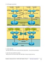
NBMA (Non Broadcast Multiple Access) hub and spoke environments. In Figure 7−1, RouterB is connected
to RouterC and RouterA via Frame Relay, both PVCs terminating on one physical interface on RouterB.
248
Figure 7−1: Split horizons
In Figure 7−1, if split horizon is not disabled on RouterB's Serial interface, then RouterC will not receive
RouterA's routing advertisements and vice versa. Use the no ip split−horizon interface subcommand to
disable split horizons.
Poison Reverse
Split horizon is a scheme used by the router to avoid problems caused by advertising routes back to the router
from which they were learned. The split horizon scheme omits routes learned from one neighbor in updates
sent to that neighbor. Split horizon with poison reverse includes the routes in updates but sets the metric to
4294967295.
When a router sees increases in routing metrics, it generally indicates a routing loop. The router then sends
poison reverse updates to remove the route and place it in holddown. In Cisco's implementation of IGRP,
poison reverse updates are sent if a route metric has increased by a factor of 1.1 or greater.
By setting the hop count to max and advertising the route back to its source, it is possible to immediately
break a routing loop. Otherwise, the inaccurate route will stay in the routing table until it times out. The
disadvantage to poison reverse is that it increases the size of the routing table.
Holddown
Holddown timers prevent the router from accepting routing information about a network for a fixed period of
time after the route has been removed from the routing table. The idea is to make sure all routers have
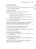
received the information, and no router sends out an invalid route. For example, in Figure 7−2 RouterB
advertises bad information to RouterC because of the delay in the routing update. Holddown counters would
prevent this from happening because RouterC would not install a new route to NetworkA for 280 seconds. By
then RouterB would have converged with the proper routing information.
Figure 7−2: Routing loop
249
Flash Updates
Flash updates are an attempt to speed up convergence time; whenever the metric of a route changes, the router
must send an update message immediately. A flash update message is sent immediately, regardless of when
the regular update message is scheduled to be sent.
IGRP Routes
IGRP advertises three types of routes: interior, system, and exterior (see Figure 7−3). Interior routes are routes
between subnets that are attached to the same router interface. System routes are routes to networks that are in
the same autonomous system, and exterior routes are routes to networks outside the autonomous system.
Figure 7−3: IGRP route types
Commands Discussed in This Chapter
clear ip route•
debug ip igrp events•
debug ip igrp transaction•
neighbor (ip−address)•
network (network−number)•
router igrp (autonomous−system number)•
show ip route igrp•
show ip protocol•
timers basic•
traffic−share {balanced | min}•
variance (multiplier)•
Definitions
clear ip route: This exec command removes one or more routes from the routing table. The command allows
you to enter a specific route or use a * to remove all routes.
debug ip igrp events: This exec command displays information on IGRP routing transactions. It displays all
IGRP routing updates that are sent or received by the router.
debug ip igrp transaction: This exec command displays transaction information on Interior Gateway
Routing Protocol (IGRP) routing transactions.
neighbor: This router configuration command permits the point−to−point (nonbroadcast) exchange of
routing information. By default, IGRP routing advertisements are sent as broadcast traffic. The neighbor
command allows advertisements to be sent to define neighbors as unicast traffic.
network: This router configuration command specifies a list of networks on which the IGRP routing process
will run. This command sends IGRP updates to the interfaces that are specified. If an interface's network is
not specified, it will not be advertised in any IGRP update.
router igrp: This global command enables the Interior Gateway Routing Protocol (IGRP) routing process on
the router. The autonomous system number used is a routing domain identifier, not a true ASN as defined in
250
RFC 1930.
show ip route igrp: This exec command displays the all IGRP learned routes.
show ip protocol: This exec command displays the current state of the active routing protocol process.
timers basic: This router configuration command allows the user to tune the IGRP timers.
update: The update timer sets the rate in seconds at which routing updates are sent. The default is 90 seconds.
invalid: The invalid timer sets the interval of time in seconds after which a route is declared invalid. The
timer is started if the route is not present in the regular update message. The default is 270 seconds.
holddown: The holddown timer sets the interval in seconds during which routing information regarding
better paths is suppressed. The idea is to make sure all routers have received the information, and no router
sends out an invalid route. The default is 280 seconds.
flush: The flush timer sets in seconds the amount of time that must pass before a route is removed from the
routing table. The default is 630 seconds.
traffic−share: This router configuration command controls how traffic is distributed among routes when
there are multiple routes to the same destination network that have different costs. The traffic can be
distributed proportionately to the ratios of the metrics or can be set to only use routes that have minimum
costs.
variance: This router configuration command controls the load balancing over multiple IGRP paths. This
command allows the administrator to load−balance across multiple paths even if the metrics of the paths are
different. By default, the amount of variance is set to 1 (equal−cost load balancing). The variance command
allows you to define how much worse an alternate path can be before that path is allowed to be used. For
example, if the variance is set to 4, the router will load−balance across paths that are up to four times as bad as
the best route.
IOS Requirements
IGRP first became available in IOS 10.0.
Lab #28: Basic IGRP Configuration
Equipment Needed
The following equipment is needed to perform this lab exercise:
Two Cisco routers with one Ethernet port and one serial port•
One Cisco router with two serial ports•
Cisco IOS 10.0 or higher•
A PC running a terminal emulation program•
Two Cisco DTE/DCE crossover cables•
One Cisco Rolled cable for access the console port of the router•
251
Configuration Overview
This configuration will demonstrate basic routing using Interior Gateway Routing Protocol (IGRP). As per
Figure 7−4, RouterA, RouterB, and RouterC will use IGRP to advertise routing information.
Figure 7−4: Basic IGRP
RouterA, RouterB, and RouterC are connected serially via a crossover cable. RouterB will act as the DCE
supplying clock to RouterA and RouterC. The IP addresses are assigned as per Figure 7−4. All routers will be
configured for IGRP and will advertise all connected networks.
Router Configurations
The configurations for the three routers in this example are as follows (key IGRP configurations are
highlighted in bold).
RouterA
Current configuration:
!
version 11.2
no service udp−small−servers
no service tcp−small−servers
!
hostname RouterA
!
interface Loopback0 ← Defines a virtual interface that will be used as a
test point
ip address 10.1.1.1 255.255.255.0
!
interface Ethernet0
ip address 148.1.1.1 255.255.255.0
no keepalive ← Disables the keep−alive on the Ethernet interface, allows
the interface to stay up when it is not attached to a hub
!
interface Serial0
ip address 192.1.1.1 255.255.255.0
!
router IGRP 64 ← Enables the IGRP routing process on the router
network 10.0.0.0 ← Specifies what interfaces will receive and send IGRP
routing updates. It also specifies what networks will be
advertised
network 148.1.0.0
network 192.1.1.0
!
no ip classless
!
!line con 0
line aux 0
line vty 0 4
login
!
end
RouterB
!
version 11.0
252
service udp−small−servers
service tcp−small−servers
!
hostname RouterB
!
!
interface Serial0
ip address 192.1.1.2 255.255.255.0
no fair−queue
clockrate 500000 ← Acts as DCE providing clock
!
interface Serial1
ip address 193.1.1.2 255.255.255.0
clockrate 500000 ← Acts as DCE providing clock
!
router igrp 64 ← Enables the IGRP routing process on the router
network 192.1.1.0 ← Specifies what interfaces will receive and send IGRP
routing updates. It also specifies what networks will be
advertised
network 193.1.1.0
!
!
line con 0
line aux 0
line vty 0 4
login
RouterC
!
version 11.1
service udp−small−servers
service tcp−small−servers
!
hostname RouterC
!
interface Ethernet0
ip address 152.1.1.1 255.255.255.0
no keepalive ← Disables the keep−alive on the Ethernet interface, allows the
interface to stay up when it is not attached to a hub
!
!
interface Serial0
ip address 193.1.1.1 255.255.255.0
!
!
router igrp 64 ← Enables the IGRP routing process on the router
network 152.1.0.0 ← Specifies what interfaces will receive and send IGRP
routing updates. It also specifies what networks will be
advertised
network 193.1.1.0
!
no ip classless
!
!
line con 0
line aux 0
line vty 0 4
login
!
end
253
Monitoring and Testing the Configuration
Like RIP, IGRP is a very simple protocol to configure and troubleshoot. Show the IP routing table on
RouterA with the show ip route command; what follows is the output from this command. Notice that two
networks were learned via IGRP, 152.1.0.0 and 193.1.1.0.
RouterA#show ip route
Codes: C − connected, S − static, I − IGRP, R − RIP, M − mobile, B − BGP
D − EIGRP, EX − EIGRP external, O − OSPF, IA − OSPF inter area
N1 − OSPF NSSA external type 1, N2 − OSPF NSSA external type 2
E1 − OSPF external type 1, E2 − OSPF external type 2, E − EGP
i − IS−IS, L1 − IS−IS level−1, L2 − IS−IS level−2, * − candidate default
U − per−user static route, o − ODR
Gateway of last resort is not set
10.0.0.0/24 is subnetted, 1 subnets
C 10.1.1.0 is directly connected, Loopback0
148.1.0.0/24 is subnetted, 1 subnets
C 148.1.1.0 is directly connected, Ethernet0
I 152.1.0.0/16 [100/10576] via 192.1.1.2, 00:00:40, Serial0
C 192.1.1.0/24 is directly connected, Serial0
I 193.1.1.0/24 [100/10476] via 192.1.1.2, 00:00:40, Serial0
From RouterA, monitor the routing updates being passed using the debug ip igrp transactions command;
what follows is the output from this command. Notice that on interface serial 0 the router does not advertise
the networks it learns from RouterB (152.1.0.0 and 193.1.1.0), but on all other interfaces these networks are
advertised. This is split horizon at work; remember when split horizon is enabled, the router will never
advertise a route back in the direction from which it came.
RouterA#debug ip igrp transactions
IGRP: sending update to 255.255.255.255 via Ethernet0 (148.1.1.1)
network 10.0.0.0, metric=501
network 152.1.0.0, metric=10576
network 192.1.1.0, metric=8476
network 193.1.1.0, metric=10476
IGRP: sending update to 255.255.255.255 via Loopback0 (10.1.1.1)
network 148.1.0.0, metric=1100
network 152.1.0.0, metric=10576
network 192.1.1.0, metric=8476
network 193.1.1.0, metric=10476
IGRP: sending update to 255.255.255.255 via Serial0 (192.1.1.1)
network 10.0.0.0, metric5501
network 148.1.0.0, metric51100
Now disable split horizons on RouterA using the interface configuration command no ip split horizons.
RouterA(config)#int s0
RouterA(config−if)#no ip split−horizon
From RouterA, monitor the routing updates being passed using the debug ip igrp transactions command;
what follows is the output from this command. Notice that now all routes are being advertised out serial 0,
including the routes learned from RouterB on serial 0.
RouterA# debug ip igrp transactions
IGRP: sending update to 255.255.255.255 via Ethernet0 (148.1.1.1)
network 10.0.0.0, metric=501
network 152.1.0.0, metric=10576
network 192.1.1.0, metric=8476
network 193.1.1.0, metric=10476
IGRP: sending update to 255.255.255.255 via Loopback0 (10.1.1.1)
network 148.1.0.0, metric=1100
network 152.1.0.0, metric=10576
254
network 192.1.1.0, metric=8476
network 193.1.1.0, metric=10476
IGRP: sending update to 255.255.255.255 via Serial0 (192.1.1.1)
network 10.0.0.0, metric=501
network 148.1.0.0, metric=1100
network 152.1.0.0, metric=10576
network 192.1.1.0, metric=8476
network 193.1.1.0, metric=10476
From RouterA, delete the IGRP process and add a new process using autonomous system 56, with the
following commands.
RouterA#configure terminal
RouterA(config)#no router igrp 64
RouterA(config)#router igrp 56
RouterA(config−router)#network 10.0.0.0
RouterA(config−router)# network 148.1.0.0
RouterA(config−router)# network 192.1.1.0
Show the IP routing table on RouterA with the show ip route command; what follows is the output from this
command. Notice that no networks are being learned via IGRP; this is because the autonomous system
numbers are different. The autonomous system number must match or the routers will not exchange routing
information.
RouterA#show ip route
Codes: C − connected, S − static, I − IGRP, R − RIP, M − mobile, B − BGP
D − EIGRP, EX − EIGRP external, O − OSPF, IA − OSPF inter area
N1 − OSPF NSSA external type 1, N2 − OSPF NSSA external type 2
E1 − OSPF external type 1, E2 − OSPF external type 2, E − EGP
i − IS−IS, L1 − IS−IS level−1, L2 − IS−IS level−2, * − candidate default
U − per−user static route, o − ODR
Gateway of last resort is not set
10.0.0.0/24 is subnetted, 1 subnets
C 10.1.1.0 is directly connected, Loopback0
148.1.0.0/24 is subnetted, 1 subnets
C 148.1.1.0 is directly connected, Ethernet0
C 192.1.1.0/24 is directly connected, Serial0
Lab #28: Basic IGRP Configuration
Equipment Needed
The following equipment is needed to perform this lab exercise:
Two Cisco routers with one Ethernet port and one serial port•
One Cisco router with two serial ports•
Cisco IOS 10.0 or higher•
A PC running a terminal emulation program•
Two Cisco DTE/DCE crossover cables•
One Cisco Rolled cable for access the console port of the router•
Configuration Overview
This configuration will demonstrate basic routing using Interior Gateway Routing Protocol (IGRP). As per
Figure 7−4, RouterA, RouterB, and RouterC will use IGRP to advertise routing information.
255
Figure 7−4: Basic IGRP
RouterA, RouterB, and RouterC are connected serially via a crossover cable. RouterB will act as the DCE
supplying clock to RouterA and RouterC. The IP addresses are assigned as per Figure 7−4. All routers will be
configured for IGRP and will advertise all connected networks.
Router Configurations
The configurations for the three routers in this example are as follows (key IGRP configurations are
highlighted in bold).
RouterA
Current configuration:
!
version 11.2
no service udp−small−servers
no service tcp−small−servers
!
hostname RouterA
!
interface Loopback0 ← Defines a virtual interface that will be used as a
test point
ip address 10.1.1.1 255.255.255.0
!
interface Ethernet0
ip address 148.1.1.1 255.255.255.0
no keepalive ← Disables the keep−alive on the Ethernet interface, allows
the interface to stay up when it is not attached to a hub
!
interface Serial0
ip address 192.1.1.1 255.255.255.0
!
router IGRP 64 ← Enables the IGRP routing process on the router
network 10.0.0.0 ← Specifies what interfaces will receive and send IGRP
routing updates. It also specifies what networks will be
advertised
network 148.1.0.0
network 192.1.1.0
!
no ip classless
!
!line con 0
line aux 0
line vty 0 4
login
!
end
RouterB
!
version 11.0
service udp−small−servers
service tcp−small−servers
!
hostname RouterB
!
!
256
interface Serial0
ip address 192.1.1.2 255.255.255.0
no fair−queue
clockrate 500000 ← Acts as DCE providing clock
!
interface Serial1
ip address 193.1.1.2 255.255.255.0
clockrate 500000 ← Acts as DCE providing clock
!
router igrp 64 ← Enables the IGRP routing process on the router
network 192.1.1.0 ← Specifies what interfaces will receive and send IGRP
routing updates. It also specifies what networks will be
advertised
network 193.1.1.0
!
!
line con 0
line aux 0
line vty 0 4
login
RouterC
!
version 11.1
service udp−small−servers
service tcp−small−servers
!
hostname RouterC
!
interface Ethernet0
ip address 152.1.1.1 255.255.255.0
no keepalive ← Disables the keep−alive on the Ethernet interface, allows the
interface to stay up when it is not attached to a hub
!
!
interface Serial0
ip address 193.1.1.1 255.255.255.0
!
!
router igrp 64 ← Enables the IGRP routing process on the router
network 152.1.0.0 ← Specifies what interfaces will receive and send IGRP
routing updates. It also specifies what networks will be
advertised
network 193.1.1.0
!
no ip classless
!
!
line con 0
line aux 0
line vty 0 4
login
!
end
Monitoring and Testing the Configuration
Like RIP, IGRP is a very simple protocol to configure and troubleshoot. Show the IP routing table on
RouterA with the show ip route command; what follows is the output from this command. Notice that two
networks were learned via IGRP, 152.1.0.0 and 193.1.1.0.
RouterA#show ip route
Codes: C − connected, S − static, I − IGRP, R − RIP, M − mobile, B − BGP
257
D − EIGRP, EX − EIGRP external, O − OSPF, IA − OSPF inter area
N1 − OSPF NSSA external type 1, N2 − OSPF NSSA external type 2
E1 − OSPF external type 1, E2 − OSPF external type 2, E − EGP
i − IS−IS, L1 − IS−IS level−1, L2 − IS−IS level−2, * − candidate default
U − per−user static route, o − ODR
Gateway of last resort is not set
10.0.0.0/24 is subnetted, 1 subnets
C 10.1.1.0 is directly connected, Loopback0
148.1.0.0/24 is subnetted, 1 subnets
C 148.1.1.0 is directly connected, Ethernet0
I 152.1.0.0/16 [100/10576] via 192.1.1.2, 00:00:40, Serial0
C 192.1.1.0/24 is directly connected, Serial0
I 193.1.1.0/24 [100/10476] via 192.1.1.2, 00:00:40, Serial0
From RouterA, monitor the routing updates being passed using the debug ip igrp transactions command;
what follows is the output from this command. Notice that on interface serial 0 the router does not advertise
the networks it learns from RouterB (152.1.0.0 and 193.1.1.0), but on all other interfaces these networks are
advertised. This is split horizon at work; remember when split horizon is enabled, the router will never
advertise a route back in the direction from which it came.
RouterA#debug ip igrp transactions
IGRP: sending update to 255.255.255.255 via Ethernet0 (148.1.1.1)
network 10.0.0.0, metric=501
network 152.1.0.0, metric=10576
network 192.1.1.0, metric=8476
network 193.1.1.0, metric=10476
IGRP: sending update to 255.255.255.255 via Loopback0 (10.1.1.1)
network 148.1.0.0, metric=1100
network 152.1.0.0, metric=10576
network 192.1.1.0, metric=8476
network 193.1.1.0, metric=10476
IGRP: sending update to 255.255.255.255 via Serial0 (192.1.1.1)
network 10.0.0.0, metric5501
network 148.1.0.0, metric51100
Now disable split horizons on RouterA using the interface configuration command no ip split horizons.
RouterA(config)#int s0
RouterA(config−if)#no ip split−horizon
From RouterA, monitor the routing updates being passed using the debug ip igrp transactions command;
what follows is the output from this command. Notice that now all routes are being advertised out serial 0,
including the routes learned from RouterB on serial 0.
RouterA# debug ip igrp transactions
IGRP: sending update to 255.255.255.255 via Ethernet0 (148.1.1.1)
network 10.0.0.0, metric=501
network 152.1.0.0, metric=10576
network 192.1.1.0, metric=8476
network 193.1.1.0, metric=10476
IGRP: sending update to 255.255.255.255 via Loopback0 (10.1.1.1)
network 148.1.0.0, metric=1100
network 152.1.0.0, metric=10576
network 192.1.1.0, metric=8476
network 193.1.1.0, metric=10476
IGRP: sending update to 255.255.255.255 via Serial0 (192.1.1.1)
network 10.0.0.0, metric=501
network 148.1.0.0, metric=1100
network 152.1.0.0, metric=10576
network 192.1.1.0, metric=8476
network 193.1.1.0, metric=10476
258
From RouterA, delete the IGRP process and add a new process using autonomous system 56, with the
following commands.
RouterA#configure terminal
RouterA(config)#no router igrp 64
RouterA(config)#router igrp 56
RouterA(config−router)#network 10.0.0.0
RouterA(config−router)# network 148.1.0.0
RouterA(config−router)# network 192.1.1.0
Show the IP routing table on RouterA with the show ip route command; what follows is the output from this
command. Notice that no networks are being learned via IGRP; this is because the autonomous system
numbers are different. The autonomous system number must match or the routers will not exchange routing
information.
RouterA#show ip route
Codes: C − connected, S − static, I − IGRP, R − RIP, M − mobile, B − BGP
D − EIGRP, EX − EIGRP external, O − OSPF, IA − OSPF inter area
N1 − OSPF NSSA external type 1, N2 − OSPF NSSA external type 2
E1 − OSPF external type 1, E2 − OSPF external type 2, E − EGP
i − IS−IS, L1 − IS−IS level−1, L2 − IS−IS level−2, * − candidate default
U − per−user static route, o − ODR
Gateway of last resort is not set
10.0.0.0/24 is subnetted, 1 subnets
C 10.1.1.0 is directly connected, Loopback0
148.1.0.0/24 is subnetted, 1 subnets
C 148.1.1.0 is directly connected, Ethernet0
C 192.1.1.0/24 is directly connected, Serial0
Lab #29: Passive Interface Configuration
Equipment Needed
The following equipment is needed to perform this lab exercise:
Two Cisco routers with one Ethernet port and one serial port•
One Cisco router with two serial ports•
Cisco IOS 10.0 or higher•
A PC running a terminal emulation program•
Two Cisco DTE/DCE crossover cables•
One Cisco Rolled cable for accessing the console port of the router•
Configuration Overview
This configuration will demonstrate the use of the passive−interface command, which allows IGRP−enabled
routers to listen to, but not send, routing updates out a particular interface. The passive−interface router
configuration command is typically used when the network router configuration command configures more
interfaces than is desirable. In Figure 7−5, for example, RouterA has three subnets (10.1.1.0/24, 10.1.2.0/24,
and 10.1.3.0/24) defined. Since IGRP is a classful protocol, when it is enabled it is turned on for the classful
network of 10.0.0.0. This encompasses all three subnets; the passive interface command allows the user to
turn off IGRP advertisements on a particular interface (subnet).
259
Figure 7−5: Passive interface
The reason IGRP changes the network entry from 10.1.1.0 to 10.0.0.0 is that IGRP is considered a "classful"
protocol. By that we mean that it recognizes the IP address class of the network address that you type and
assumes the proper mask. For a Class A network like this one, the mask is 255.0.0.0, yielding 10.0.0.0 (no
matter what you actually type as the last two octets). The network statement tells the routing protocol to route
on the interfaces where the network address matches the one specified in the network statement.
In this lab scenario, the user only wishes to send IGRP updates out network 10.1.2.0, so interface E0
(10.1.1.0) and S1 (10.1.3.0) are made passive interfaces.
RouterA, RouterB, and RouterC are connected serially via a crossover cable. RouterB will act as the DCE
supplying clock to RouterA and RouterC. The IP addresses are assigned as per Figure 7−6. All routers will be
configured for IGRP; RouterB and RouterC will advertise all connected networks. RouterA's interface S0 will
be passive and will not advertise any routing information; however, it will still receive routing updates.
Figure 7−6: IGRP Passive Interface Configuration
Router Configurations
The configurations for the three routers in this example are as follows (key IGRP configurations are
highlighted in bold).
RouterA
Current configuration:
!
version 11.2
no service udp−small−servers
no service tcp−small−servers
!
hostname RouterA
!
interface Loopback0 ← Defines a virtual interface that will be used as a
test point
ip address 10.1.1.1 255.255.255.0
!
interface Ethernet0
ip address 148.1.1.1 255.255.255.0
no keepalive ← Disables the keep−alive on the Ethernet interface, allows the
interface to stay up when it is not attached to a hub
!
interface Serial0
ip address 192.1.1.1 255.255.255.0
!
!
router IGRP 64 ← Enables the IGRP routing process on the router
passive−interface Serial0 ← Disables the sending of IGRP updates on interface
Serial 0
network 10.0.0.0 ← Specifies what interfaces will receive and send IGRP routing
updates. It also specifies what networks will be advertised
network 148.1.0.0
network 192.1.1.0
!
260
no ip classless
!
!line con 0
line aux 0
line vty 0 4
login
!
end
RouterB
!
version 11.0
service udp−small−servers
service tcp−small−servers
!
hostname RouterB
!
!
interface Serial0
ip address 192.1.1.2 255.255.255.0
no fair−queue
clockrate 500000 ← Acts as DCE providing clock
!
interface Serial1
ip address 193.1.1.2 255.255.255.0
clockrate 500000 ← Acts as DCE providing clock
!
router igrp 64 ← Enables the IGRP routing process on the router
network 192.1.1.0 ← Specifies what interfaces will receive and send IGRP
routing updates. It also specifies what networks will be
advertised
network 193.1.1.0
!
!
line con 0
line aux 0
line vty 0 4
login
RouterC
!
version 11.1
service udp−small−servers
service tcp−small−servers
!
hostname RouterC
!
interface Ethernet0
ip address 152.1.1.1 255.255.255.0
no keepalive ← Disables the keep−alive on the Ethernet interface, allows the
interface to stay up when it is not attached to a hub
!
!
interface Serial0
ip address 193.1.1.1 255.255.255.0
!
!
router igrp 64 ← Enables the IGRP routing process on the router
network 152.1.0.0 ← Specifies what interfaces will receive and send IGRP
routing updates. It also specifies what networks will be
advertised
network 193.1.1.0
!
261
no ip classless
!
!
line con 0
line aux 0
line vty 0 4
login
!
end
Monitoring and Testing the Configuration
Display the information about IGRP with the command show ip protocols, noticing that RouterA's serial
interface is passive.
RouterA#show ip protocols
Routing Protocol is "igrp 64"
Sending updates every 90 seconds, next due in 31 seconds
Invalid after 270 seconds, hold down 280, flushed after 630
Outgoing update filter list for all interfaces is not set
Incoming update filter list for all interfaces is not set
Default networks flagged in outgoing updates
Default networks accepted from incoming updates
IGRP metric weight K1=1, K2=0, K3=1, K4=0, K5=0
IGRP maximum hopcount 100
IGRP maximum metric variance 1
Redistributing: igrp 64
Routing for Networks:
10.0.0.0
148.1.0.0
192.1.1.0
Passive Interface(s):
Serial0
Routing Information Sources:
Gateway Distance Last Update
192.1.1.2 100 00:00:48
Distance: (default is 100)
What follows is the output from the debug ip igrp transactions command on RouterA. Notice that IGRP
updates are only being sent out interface Ethernet 0 and Loopback 0; also note that interface S0 is still
receiving IGRP updates.
RouterA#debug ip igrp transactions
IGRP: sending update to 255.255.255.255 via Ethernet0 (148.1.1.1)
network 10.0.0.0, metric=501
network 152.1.0.0, metric=10576
network 192.1.1.0, metric=8476
network 193.1.1.0, metric=10476
IGRP: sending update to 255.255.255.255 via Loopback0 (10.1.1.1)
network 148.1.0.0, metric=1100
network 152.1.0.0, metric=10576
network 192.1.1.0, metric=8476
network 193.1.1.0, metric=10476
IGRP: received update from 192.1.1.2 on Serial0
network 152.1.0.0, metric 10576 (neighbor 8576)
network 193.1.1.0, metric 10476 (neighbor 8476)
What follows is the output from the show ip route command on RouterA and RouterC. Note that RouterA has
learned all of the routes from RouterC, but RouterC has no routes from RouterA.
RouterA#show ip route
Codes: C − connected, S − static, I − IGRP, R − RIP, M − mobile, B − BGP
D − EIGRP, EX − EIGRP external, O − OSPF, IA − OSPF inter area
262
N1 − OSPF NSSA external type 1, N2 − OSPF NSSA external type 2
E1 − OSPF external type 1, E2 − OSPF external type 2, E − EGP
i − IS−IS, L1 − IS−IS level−1, L2 − IS−IS level−2, * − candidate default
U − per−user static route, o − ODR
Gateway of last resort is not set
10.0.0.0/24 is subnetted, 1 subnets
C 10.1.1.0 is directly connected, Loopback0
148.1.0.0/24 is subnetted, 1 subnets
C 148.1.1.0 is directly connected, Ethernet0
I 152.1.0.0/16 [100/10576] via 192.1.1.2, 00:00:29, Serial0
C 192.1.1.0/24 is directly connected, Serial0
I 193.1.1.0/24 [100/10476] via 192.1.1.2, 00:00:29, Serial0
RouterC#show ip route
Codes: C − connected, S − static, I − IGRP, R − RIP, M − mobile, B − BGP
D − EIGRP, EX − EIGRP external, O − OSPF, IA − OSPF inter area
N1 − OSPF NSSA external type 1, N2 − OSPF NSSA external type 2
E1 − OSPF external type 1, E2 − OSPF external type 2, E − EGP
i − IS−IS, L1 − IS−IS level−1, L2 − IS−IS level−2, * − candidate default
U − per−user static route, o − ODR
Gateway of last resort is not set
152.1.0.0/24 is subnetted, 1 subnets
C 152.1.1.0 is directly connected, Ethernet0
I 192.1.1.0/24 [100/10476] via 193.1.1.2, 00:00:13, Serial0 ← Route from RouterB
C 193.1.1.0/24 is directly connected, Serial0
Lab #30: IGRP Unequal−Cost Load Balancing
Equipment Needed
The following equipment is needed to perform this lab exercise:
Two Cisco routers with one Ethernet port and one serial port•
One Cisco router with two serial ports and one Ethernet port•
Cisco IOS 10.0 or higher•
A PC running a terminal emulation program•
Two Ethernet cables•
One Ethernet hub•
Two Cisco DTE/DCE crossover cables•
One Cisco Rolled cable for accessing the console port of the router•
Overview
IGRP can be configured to load−balance on up to four unequal−cost paths to a given destination. This feature
is known as unequal−cost load balancing and is set using the variance command. By default, the router will
load balance across up to four equal−cost paths, and the variance command lets you set how much worse an
alternate path can be (in terms of metrics) and still be used to load−balance across.
For example, if RouterA has two routes to network 1.1.1.1, one with a cost of 4 and one with a cost of 8, by
default the route will only use the path with a cost of 4 when sending packets to 1.1.1.1. However, if a
variance of 2 is set, the router will load−balance across both paths. This is because the route with the cost of 8
is within the variance, which in this case can be up to two times as bad as the preferred route (4 (preferred
route) * 2 = 8).
263
Configuration Overview
This configuration will demonstrate the use of the variance command, which allows IGRP−enabled routers to
load−balance across unequal−cost paths. The variance command will be set on RouterA so that both paths to
network 3.3.3.3 are used.
RouterA, RouterB, and RouterC are connected serially via a crossover cable, and RouterA and RouterB are
also connected via an Ethernet hub. RouterB will act as the DCE supplying clock to RouterA and RouterC.
The IP addresses are assigned as per Figure 7−7. All routers will be configured for IGRP; RouterA will be
configured to load−balance traffic that is destined for 3.3.3.3 over two unequal−cost paths.
Figure 7−7: IGRP unequal−cost load balancing
Router Configurations
The configurations for the three routers in this example are as follows (key IGRP configurations are
highlighted in bold).
RouterA
Current configuration:
!
version 11.2
no service udp−small−servers
no service tcp−small−servers
!
hostname RouterA
!
interface Loopback0 ← Defines a virtual interface that will be used as a
test point
ip address 10.1.1.1 255.255.255.0
!
interface Ethernet0
ip address 152.1.1.1 255.255.255.0
keepalive
!
interface Serial0
ip address 192.1.1.1 255.255.255.0
!
!
router IGRP 64 ← Enables the IGRP routing process on the router
variance 2
network 10.0.0.0 ← Specifies what interfaces will receive and send IGRP
routing updates. It also specifies what networks will be
advertised
network 152.1.0.0
network 192.1.1.0
!
no ip classless
!
!
line con 0
line aux 0
line vty 0 4
login
!
264