all in one cisco ccie lab study guide second edition phần 5 potx
Bạn đang xem bản rút gọn của tài liệu. Xem và tải ngay bản đầy đủ của tài liệu tại đây (803.85 KB, 89 trang )
router ospf 64 ← Enables OSPF process 64 on the router
network 192.1.1.0 0.0.0.255 area 0 ← Specifies what interface OSPF will be run
on and what area the interface will be in
network 2.2.2.2 0.0.0.0 area 0
network 193.1.1.0 0.0.0.255 area 0
!
no ip classless
!
!
line con 0
line aux 0
line vty 0 4
login
!
end
RouterC
!
version 11.2
no service udp−small−servers
no service tcp−small−servers
!
hostname RouterC
!
!
interface Loopback0 ← Defines a virtual interface the IP address is used as the
router ID
ip address 3.3.3.3 255.255.255.0
!
interface Ethernet0/0
ip address 10.1.1.2 255.255.255.0
!
interface Serial0/0
ip address 193.1.1.1 255.255.255.0
!
interface Serial0/1
no ip address
shutdown
!
!
router ospf 64 ← Enables OSPF process 64 on the router
network 192.1.1.0 0.0.0.255 area 0
network 3.3.3.3 0.0.0.0 area 0
network 10.1.1.0 0.0.0.255 area 0
!
no ip classless
!
!
line con 0
line aux 0
line vty 0 4
login
!
end
Monitoring and Testing the Configuration
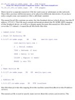
From RouterA, show the OSPF interface statistics with the command show ip ospf interface s0/0. Notice that
the hello and dead intervals have been changed and the OSPF cost of sending a packet out the interface has
changed to 66.
329
RouterA#show ip ospf int s0/0
Serial0 is up, line protocol is up
Internet Address 192.1.1.1/24, Area 0
Process ID 64, Router ID 192.1.1.1, Network Type POINT_TO_POINT, Cost: 66
Transmit Delay is 1 sec, State POINT_TO_POINT,
Timer intervals configured, Hello 20, Dead 120, Wait 120, Retransmit 5
Hello due in 00:00:08
Neighbor Count is 1, Adjacent neighbor count is 1
Adjacent with neighbor 193.1.1.2
Suppress hello for 0 neighbor(s)
Display the routing table on RouterA with the command show ip route. Notice the cost of reaching the
loopback interface on RouterC (3.3.3.3) is 11. The reason that it is 11 is the cost of the Ethernet is 10 and the
cost of a loopback interface is 1.
RouterA#show ip route
Codes: C − connected, S − static, I − IGRP, R − RIP, M − mobile, B − BGP
D − EIGRP, EX − EIGRP external, O − OSPF, IA − OSPF inter area
N1 − OSPF NSSA external type 1, N2 − OSPF NSSA external type 2
E1 − OSPF external type 1, E2 − OSPF external type 2, E − EGP
i − IS−IS, L1 − IS−IS level−1, L2 − IS−IS level−2, * − candidate default
U − per−user static route, o − ODR
Gateway of last resort is not set
1.0.0.0/24 is subnetted, 1 subnets
C 1.1.1.0is directly connected, Loopback0
2.0.0.0/32 is subnetted, 1 subnets
O 2.2.2.2[110/67] via 192.1.1.2, 00:15:08, Serial0
3.0.0.0/32 is subnetted, 1 subnets
O 3.3.3.3 [110/11] via 10.1.1.2, 00:15:08, Ethernet0
10.0.0.0/24 is subnetted, 1 subnets
C 10.1.1.0 is directly connected, Ethernet0
C 192.1.1.0/24 is directly connected, Serial0
193.1.1.0/24 [110/74] via 10.1.1.2, 00:15:08, Ethernet0
Notice the cost of reaching the loopback interface on RouterC (3.3.3.3) is 11. The reason that it is 11 is that
the OSPF cost of sending a packet out the Ethernet on RouterA is 10 and the cost of sending a packet out the
loopback interface on RouterC is 1. This can been seen by displaying the OSPF statisics on RouterA's
Ethernet interface and RouterC's loopback interface.
RouterA#show ip ospf interface e0/0
Ethernet0 is up, line protocol is up
Internet Address 10.1.1.1/24, Area 0
Process ID 64, Router ID 192.1.1.1, Network Type BROADCAST, Cost: 10
Transmit Delay is 1 sec, State DR, Priority 1
Designated Router (ID) 192.1.1.1, Interface address 10.1.1.1
Backup Designated router (ID) 3.3.3.3, Interface address 10.1.1.2
Timer intervals configured, Hello 10, Dead 40, Wait 40, Retransmit 5
Hello due in 00:00:09
Neighbor Count is 1, Adjacent neighbor count is 1
Adjacent with neighbor 3.3.3.3 (Backup Designated Router)
Suppress hello for 0 neighbor(s)
RouterC#show ip ospf int loopback 0
Loopback0 is up, line protocol is up
Internet Address 3.3.3.3/24, Area 0
Process ID 64, Router ID 3.3.3.3, Network Type LOOPBACK, Cost: 1
Loopback interface is treated as a stub Host
Change the OSPF cost of RouterA's Ethernet interface to 200.
RouterA#configure terminal
RouterA(config)#interface e0/0
RouterA(config−if)#ip ospf cost 200
330
Display the routing table on RouterA with the command show ip route. Notice that the route to 3.3.3.3 has
now changed; RouterA now uses the path over the serial interface, which has a cost of 131, which is now
lower than the new cost of using the Ethernet interface.
RouterA#show ip route
Codes: C − connected, S − static, I − IGRP, R − RIP, M − mobile, B − BGP
D − EIGRP, EX − EIGRP external, O − OSPF, IA − OSPF inter area
N1 − OSPF NSSA external type 1, N2 − OSPF NSSA external type 2
E1 − OSPF external type 1, E2 − OSPF external type 2, E − EGP
i − IS−IS, L1 − IS−IS level−1, L2 − IS−IS level−2, * − candidate default
U − per−user static route, o − ODR
Gateway of last resort is not set
1.0.0.0/24 is subnetted, 1 subnets
C 1.1.1.0 is directly connected, Loopback0
2.0.0.0/32 is subnetted, 1 subnets
O 2.2.2.2 [110/67] via 192.1.1.2, 00:03:20, Serial0
3.0.0.0/32 is subnetted, 1 subnets
O 3.3.3.3 [110/131] via 192.1.1.2, 00:03:20, Serial0
10.0.0.0/24 is subnetted, 1 subnets
Now let's take a look at what happens when the hello intervals do not match on routers connected to the same
network. On RouterA's serial interface, change the hello interval to 30 seconds.
RouterA#configure terminal
RouterA(config)#interface s0/0
RouterA(config−if)#ip ospf hello−interval 30
Display the status of the OSPF neighbors on RouterA with the command show ip ospf neighbor. The
neighbor relationship with RouterB is gone.
RouterA#show ip ospf neighbor
Neighbor ID Pri State Dead Time Address Interface
3.3.3.3 1 FULL/BDR 00:00:37 10.1.1.2 Ethernet0
Monitor the OSPF events on RouterA with command debug ip ospf events. Notice that RouterA is receiving
an OSPF packet from RouterB and the hello intervals do not match. If either the hello interval or the dead
interval do not match, then the router will not form an adjacency with its neighbor.
RouterA#
OSPF: Mismatched hello parameters from 192.1.1.2
Lab #41: Inter−Area and External Route Summarization
Equipment Needed
The following equipment is needed to perform this lab exercise:
Two Cisco routers, each having one serial port and one Ethernet port•
Two Cisco routers, each having one serial port and two Ethernet ports•
One Cisco router with an Ethernet port•
Cisco IOS 10.0 or higher•
A PC running a terminal emulation program•
Two Cisco V.35 DCE/DTE crossover cables•
Two Ethernet hub and four Ethernet cables (or two Ethernet Crossover cables)•
Cisco rolled cable for console port access•
331
Overview
Cisco allows you to summarize addresses in order to conserve resources by limiting the number of routes that
need to be advertised between areas. Two types of address summarization are supported on a Cisco router:
inter−area summarization and external route summarization. Inter−area summarization is used to summarize
addresses between areas, while external summarization is used to summarize a set of external routes that have
been injected into the domain.
Configuration Overview
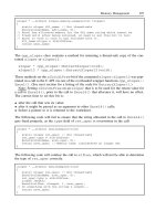
This lab will demonstrate the various summarization techniques used in OSPF. Since area 0 contains all of the
addresses for subnetwork 152.1.1.0, they can all be summarized by RouterB and RouterC in one update,
152.1.1.0/24. In addition, RouterD is acting as a ASBR redistributing the RIP learned routes from RouterE
into OSPF. The seven networks can be summarized into one network entry (130.1.0.0/21).
To do this, the area range command is used, which specifies the area that the summary belongs to, the
summary address, and the mask.
RouterA will attach to RouterB via a V.35 crossover cable. RouterB will act as the DCE supplying clock to
RouterA. RouterB and RouterC will be attached via an Ethenet hub. RouterC will attach to RouterD via a
V.35 crossover cable. RouterC will act as the DCE supplying clock to RouterD. RouterD will attach to
RouterE via an Ethenet hub. The second Ethernet interfaces on RouterB and RouterC will not attach to
anything, so keep−alives will need to be disabled. The reason that Ethernet interfaces were used instead of
loopback interfaces is that loopback interfaces are advertised as /32 networks across area boundaries.
RIP is run between RouterD and RouterE; RouterE will advertise all subnetworks that are attached. RouterD
will redistribute the RIP learned routes into OSPF; mutual redistribution is not used, since it is not needed to
illustrate summarization. However, if you want RouterE to see the OSPF networks, it will need to be added.
All IP addresses are as per Figure 8−15.
Figure 8−15: OSPF route summarization
Router Configurations
The configurations for the routers in this example are as follows (key OSPF commands are highlighted in
bold).
RouterA
Building configuration
Current configuration:
!
version 11.2
no service udp−small−servers
332
no service tcp−small−servers
!
hostname RouterA
!
!
interface Ethernet0
ip address 192.1.1.2 255.255.255.0
!
interface Serial0
ip address 152.1.2.1 255.255.255.252
!
router ospf 64 ← Enables OSPF process 64 on the router
network 152.1.2.0 0.0.0.255 area 1 ← Specifies what interface OSPF will be run
on and what area the interface will be in
!
line con 0
line 1 16
no exec
transport input all
line aux 0
line vty 0 4
password cisco
login
!
end
RouterB
Current configuration:
!
version 11.2
!
hostname RouterB
!
!
interface Ethernet 1/0
ip address 152.1.1.129 255.255.255.192
no keepalive
!
interface Ethernet0/0
ip address 152.1.1.1 255.255.255.128
!
interface Serial0/0
ip address 152.1.2.2 255.255.255.252
no ip directed−broadcast
no ip mroute−cache
no fair−queue
clockrate 1000000
!
router ospf 64 ← Enables OSPF process 64 on the router
network 152.1.1.0 0.0.0.255 area 0 ← Specifies what interface OSPF will be run
on and what area the interface will be in
network 152.1.2.0 0.0.0.255 area 1
!
ip classless
no ip http server
!
!
line con 0
transport input none
line aux 0
line vty 0 4
!
end
!
333
RouterC
Current configuration:
!
hostname RouterC
!
interface Ethernet 1/0
ip address 152.1.1.193 255.255.255.192
no ip directed−broadcast
no keepalive
!
interface Ethernet0/0
ip address 152.1.1.2 255.255.255.128
no ip directed−broadcast
!
interface Serial0/0
ip address 152.1.3.2 255.255.255.252
no ip directed−broadcast
no ip mroute−cache
no fair−queue
clockrate 1000000
!
!
router ospf 64 ← Enables OSPF process 64 on the router
network 152.1.1.0 0.0.0.255 area 0
network 152.1.3.0 0.0.0.255 area 2
!
ip classless
no ip http server
!
line con 0
transport input none
line aux 0
line vty 0 4
!
end
RouterD
Current configuration:
!
version 11.2
!
hostname RouterD
!
!
interface Ethernet0
ip address 130.1.4.1 255.255.255.0
no ip directed−broadcast
!
interface Serial0
ip address 152.1.3.1 255.255.255.252
no ip directed−broadcast
ip ospf interface−retry 0
!
router ospf 64 ← Enables OSPF process 64 on the router
redistribute rip metric 10 subnets ← Redistributes RIP into OSPF (For this lab
exercise only one way redistribution is
needed)
network 152.1.3.0 0.0.0.255 area 2
network 152.1.3.0 0.0.0.255 area 2
!
router rip ← Enables RIP routing
network 130.1.0.0
!
334
no ip classless
!
!
line con 0
transport input none
line aux 0
line vty 0 4
login
!
end
RouterE
version 11.2
!
hostname RouterE
!
interface Loopback0
ip address 130.1.1.1 255.255.255.0
no ip directed−broadcast
!
interface Loopback1
ip address 130.1.2.1 255.255.255.0
no ip directed−broadcast
!
interface Loopback2
ip address 130.1.3.1 255.255.255.0
no ip directed−broadcast
!
interface Loopback3
ip address 130.1.5.1 255.255.255.0
no ip directed−broadcast
!
interface Loopback4
ip address 130.1.6.1 255.255.255.0
no ip directed−broadcast
no ip directed−broadcast
!
interface Loopback5
ip address 130.1.7.1 255.255.255.0
no ip directed−broadcast
!
interface Ethernet0
ip address 130.1.4.2 255.255.255.0
no ip directed−broadcast
!
router rip ← Enables RIP routing
network 130.1.0.0
!
ip classless
!
line con 0
transport input none
line aux 0
line vty 0 4
!
end
Monitoring and Testing the Configuration
Display the routing table on RouterA with command show ip route. What follows is the output from the
command; notice that RouterA has an entry for networks 152.1.1.128/26, 152.1.1.192/26, and 152.1.1.0/25.
RouterA#show ip route
Codes: C − connected, S − static, I − IGRP, R − RIP, M − mobile, B − BGP
335
D − EIGRP, EX − EIGRP external, O − OSPF, IA − OSPF inter area
N1 − OSPF NSSA external type 1, N2 − OSPF NSSA external type 2
E1 − OSPF external type 1, E2 − OSPF external type 2, E − EGP
i − IS−IS, L1 − IS−IS level−1, L2 − IS−IS level−2, * − candidate default
U − per−user static route, o − ODR
Gateway of last resort is not set
130.1.0.0/24 is subnetted, 7 subnets
O E2 130.1.3.0 [110/10] via 152.1.2.2, 00:19:45, Serial0
O E2 130.1.2.0 [110/10] via 152.1.2.2, 00:19:45, Serial0
O E2 130.1.1.0 [110/10] via 152.1.2.2, 00:19:45, Serial0
O E2 130.1.7.0 [110/10] via 152.1.2.2, 00:19:45, Serial0
O E2 130.1.6.0 [110/10] via 152.1.2.2, 00:19:45, Serial0
O E2 130.1.5.0 [110/10] via 152.1.2.2, 00:19:45, Serial0
O E2 130.1.4.0 [110/10] via 152.1.2.2, 00:19:45, Serial0
152.1.0.0/16 is variably subnetted, 5 subnets, 4 masks
O IA 152.1.1.128/26 [110/65] via 152.1.2.2, 00:19:49, Serial0
O IA 152.1.1.192/26 [110/84] via 152.1.2.2, 00:00:22, Serial0
O IA 152.1.1.0/25 [110/74] via 152.1.2.2, 00:19:49, Serial0
O IA 152.1.3.0/30 [110/122] via 152.1.2.2, 00:19:49, Serial0
C 152.1.2.0/30 is directly connected, Serial0
C 192.1.1.0/24 is directly connected, Ethernet0
Since all of these networks are part of Area 0, the area border routers (ABRs) RouterB and RouterC can
summarize the networks into one entry, 152.1.1.0 /24. To do this, add the following commands to RouterB
and RouterC under the OSPF process.
RouterB(config)#router ospf 64
RouterB(config−router)#area 0 range 152.1.1.0 255.255.255.0
RouterC(config)#router ospf 64
RouterC(config−router)#area 0 range 152.1.1.0 255.255.255.0
Display the routing table on RouterA with the command show ip route. What follows is the output from the
command; notice that RouterA now only has one entry, 152.1.1.0 /24, instead of three.
RouterA#show ip route
Codes: C − connected, S − static, I − IGRP, R − RIP, M − mobile, B − BGP
D − EIGRP, EX − EIGRP external, O − OSPF, IA − OSPF inter area
N1 − OSPF NSSA external type 1, N2 − OSPF NSSA external type 2
E1 − OSPF external type 1, E2 − OSPF external type 2, E − EGP
i − IS−IS, L1 − IS−IS level−1, L2 − IS−IS level−2, * − candidate default
U − per−user static route, o − ODR
Gateway of last resort is not set
130.1.0.0/24 is subnetted, 7 subnets
O E2 130.1.3.0 [110/10] via 152.1.2.2, 00:27:23, Serial0
O E2 130.1.2.0 [110/10] via 152.1.2.2, 00:27:23, Serial0
O E2 130.1.1.0 [110/10] via 152.1.2.2, 00:27:23, Serial0
O E2 130.1.7.0 [110/10] via 152.1.2.2, 00:27:23, Serial0
O E2 130.1.6.0 [110/10] via 152.1.2.2, 00:27:23, Serial0
O E2 130.1.5.0 [110/10] via 152.1.2.2, 00:27:23, Serial0
O E2 130.1.4.0 [110/10] via 152.1.2.2, 00:27:23, Serial0
152.1.0.0/16 is variably subnetted, 3 subnets, 2 masks
O IA 152.1.1.0/24 [110/84] via 152.1.2.2, 00:01:42, Serial0
O IA 152.1.3.0/30 [110/122] via 152.1.2.2, 00:27:27, Serial0
C 152.1.2.0/30 is directly connected, Serial0
C 192.1.1.0/24 is directly connected, Ethernet0
RouterD is acting as an ASBR, redistributing the RIP learned routes from RouterE into OSPF. Display the
routing table on RouterA with the command show ip route. What follows is the output from the command;
notice that RouterA has entries for all seven networks.
336
RouterA# sho ip route
Codes: C − connected, S − static, I − IGRP, R − RIP, M − mobile, B − BGP
D − EIGRP, EX − EIGRP external, O − OSPF, IA − OSPF inter area
N1 − OSPF NSSA external type 1, N2 − OSPF NSSA external type 2
E1 − OSPF external type 1, E2 − OSPF external type 2, E − EGP
i − IS−IS, L1 − IS−IS level−1, L2 − IS−IS level−2, * − candidate default
U − per−user static route, o − ODR
Gateway of last resort is not set
130.1.0.0/24 is subnetted, 7 subnets
O E2 130.1.3.0 [110/10] via 152.1.2.2, 00:36:40, Serial0
O E2 130.1.2.0 [110/10] via 152.1.2.2, 00:36:40, Serial0
O E2 130.1.1.0 [110/10] via 152.1.2.2, 00:36:40, Serial0
O E2 130.1.7.0 [110/10] via 152.1.2.2, 00:36:40, Serial0
O E2 130.1.6.0 [110/10] via 152.1.2.2, 00:36:40, Serial0
O E2 130.1.5.0 [110/10] via 152.1.2.2, 00:36:40, Serial0
O E2 130.1.4.0 [110/10] via 152.1.2.2, 00:36:40, Serial0
152.1.0.0/16 is variably subnetted, 3 subnets, 2 masks
O IA 152.1.1.0/24 [110/84] via 152.1.2.2, 00:10:59, Serial0
O IA 152.1.3.0/30 [110/122] via 152.1.2.2, 00:36:44, Serial0
C 152.1.2.0/30 is directly connected, Serial0
C 192.1.1.0/24 is directly connected, Ethernet0
The networks range from 130.1.1.0 to 130.1.7.0; since these are contiguous, they can be summarized into one
entry by the ASBR. To accomplish this, add the following command to RouterD under the OSPF process.
RouterD(config)#router ospf 64
RouterD(config−router)#summary−address 130.1.0.0 255.255.248.0
Without summarization, a router advertising these seven networks would need to send a separate route update
for each of these networks. Summarization allows a router to advertise more than one network with a single
advertisement. In the case of our seven networks, they can be advertised as 130.1.0.0 with a 21−bit mask.
In the table that follows, we see that all seven networks have an exact match for their first 21 bits. Notice that
the .1, .2, .3, .4, .5, .6, and .7 networks use seven combinations of the three remaining bits (.0 is not used).
Thus, a 21−bit mask can be used to summarize the networks.
Display the routing table on RouterA; what follows is the output. Notice that the seven entries are gone and
only one entry exits (network 130.1.0.0 /21).
RouterA#SHO IP ROute
Codes: C − connected, S − static, I − IGRP, R − RIP, M − mobile, B − BGP
D − EIGRP, EX − EIGRP external, O − OSPF, IA − OSPF inter area
N1 − OSPF NSSA external type 1, N2 − OSPF NSSA external type 2
E1 − OSPF external type 1, E2 − OSPF external type 2, E − EGP
i − IS−IS, L1 − IS−IS level−1, L2 − IS−IS level−2, * − candidate default
U − per−user static route, o − ODR
Gateway of last resort is not set
130.1.0.0/21 is subnetted, 1 subnets
337
O E2 130.1.0.0 [110/10] via 152.1.2.2, 00:03:00, Serial0
152.1.0.0/16 is variably subnetted, 3 subnets, 2 masks
O IA 152.1.1.0/24 [110/84] via 152.1.2.2, 00:03:00, Serial0
O IA 152.1.3.0/30 [110/122] via 152.1.2.2, 00:03:00, Serial0
C 152.1.2.0/30 is directly connected, Serial0
C 192.1.1.0/24 is directly connected, Ethernet0
Lab #42: Regular, Stub, Totally Stub, and NSSA Areas
Equipment Needed
The following equipment is needed to perform this lab exercise:
Two Cisco routers, each having one serial port and one Ethernet port•
Two Cisco routers, each having one serial port and two Ethernet ports•
One Cisco router with an Ethernet port•
Cisco IOS 10.0 or higher•
A PC running a terminal emulation program•
Two Cisco V.35 DCE/DTE crossover cables•
Two Ethernet hub and four Ethernet cables (or two Ethernet Crossover cables)•
Cisco rolled cable for console port access•
Overview
Cisco routers support multiple area types (Regular, Stub, NSSA, and Totally Stub); the difference in area
types lies in the kind of LSAs that are permitted in the area.
In a regular area, all types of LSAs are permitted. The benefit is that all routers have all routing information
and therefore, have the best path to the destination. The drawback is that any flap caused by a link failure
outside the area will cause a partial SPF calculation.
In a stub area, no external LSAs are permitted; therefore, none are injected by the ABR. External LSAs are
used to describe destinations outside the OSPF domain. For example, a route received from another routing
protocol, such as RIP, and redistributed into OSPF is considered external and would be advertised in an
external LSA.
While stub areas prevent flapping outside of the domain from affecting the area, they do not prevent flapping
that occurs within the domain from affecting the area. Since summary LSAs are still permitted, flaps that
occur in other areas will still affect the stub area.
Totally stubby areas, like stub areas, prevent external LSAs. Unlike a stub area, however, totally stubby areas
do not permit summary LSAs. So flaps that occur within other areas will not affect the totally stubby area.
An NSSA area is similar to a stub area; however, it can import external routes into the area. The routes are
carried across the area as type 7 LSAs and converted to type 5 LSAs by the ABR. A NSSA area would be
used if, for example, you wanted to prevent external LSAs from entering the area, but you still needed to send
external LSAs out of the area, for example, if one of the routers in the area was a ASBR.
Configuration Overview
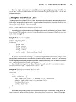
This lab will demonstrate the various area types used in OSPF. The connectivity and addressing are the same
as in Lab #41.
338
RouterA will attach to RouterB via a V.35 crossover cable. RouterB will act as the DCE supplying clock to
RouterA. RouterB and RouterC will be attached via an Ethenet hub. RouterC will attach to RouterD via a
V.35 crossover cable. RouterC will act as the DCE supplying clock to RouterD. RouterD will attach to
RouterE via an Ethenet hub. The second Ethernet interfaces on RouterB and RouterC will not attach to
anything, so keep−alives will need to be disabled. The reason that Ethernet interfaces were used instead of
loopback interfaces is that loopback interfaces are advertised as /32 networks across area boundaries.
RIP is run between RouterD and RouterE; RouterE will advertise all subnetworks that are attached. RouterD
will redistribute the RIP learned routes into OSPF; mutual redistribution is not used. However, if you want
RouterE to see the OSPF networks, it will need to be added. All IP addresses are as per Figure 8−16.
Figure 8−16: OSPF stub areas
Router Configurations
The configurations for the routers in this example are as follows (key OSPF commands are highlighted in
bold).
RouterA
Building configuration
Current configuration:
!
version 11.2
no service udp−small−servers
no service tcp−small−servers
!
hostname RouterA
!
!
interface Ethernet0
ip address 192.1.1.2 255.255.255.0
!
interface Serial0
ip address 152.1.2.1 255.255.255.252
!
router ospf 64 ← Enables OSPF process 64 on the router
network 152.1.2.0 0.0.0.255 area 1 ← Specifies what interface OSPF will be run
on and what area the interface will be in
!
line con 0
line 1 16
no exec
transport input all
line aux 0
line vty 0 4
password cisco
339
login
!
end
RouterB
Current configuration:
!
version 11.2
!
hostname RouterB
!
!
interface Ethernet 1/0
ip address 152.1.1.129 255.255.255.192
no keepalive
!
interface Ethernet0/0
ip address 152.1.1.1 255.255.255.128
!
interface Serial0/0
ip address 152.1.2.2 255.255.255.252
no ip directed−broadcast
no ip mroute−cache
no fair−queue
clockrate 1000000
!
router ospf 64 ← Enables OSPF process 64 on the router
area 0 range 152.1.1.0 255.255.255.0
network 152.1.1.0 0.0.0.255 area 0 ← Specifies what interface OSPF will be run
on and what area the interface will be in
network 152.1.2.0 0.0.0.255 area 1
!
ip classless
no ip http server
!
!
line con 0
transport input none
line aux 0
line vty 0 4
!
end
!
RouterC
Current configuration:
!
hostname RouterC
!
interface Ethernet 1/0
ip address 152.1.1.193 255.255.255.192
no ip directed−broadcast
no keepalive
!
interface Ethernet0/0
ip address 152.1.1.2 255.255.255.128
no ip directed−broadcast
!
interface Serial0/0
ip address 152.1.3.2 255.255.255.252
no ip directed−broadcast
no ip mroute−cache
no fair−queue
clockrate 1000000
340
!
!
router ospf 64 ← Enables OSPF process 64 on the router
area 0 range 152.1.1.0 255.255.255.0
network 152.1.1.0 0.0.0.255 area 0
network 152.1.3.0 0.0.0.255 area 2
!
ip classless
no ip http server
!
line con 0
transport input none
line aux 0
line vty 0 4
!
end
RouterD
Current configuration:
!
version 11.2
!
hostname RouterD
!
!
interface Ethernet0
ip address 130.1.4.1 255.255.255.0
no ip directed−broadcast
!
interface Serial0
ip address 152.1.3.1 255.255.255.252
no ip directed−broadcast
ip ospf interface−retry 0
!
router ospf 64 ← Enables OSPF process 64 on the router
summary−address 130.1.0.0 255.255.248.0
redistribute rip metric 10 subnets ← Redistributes RIP into OSPF (For this lab
exercise only one way redistribution is
needed)
network 152.1.3.0 0.0.0.255 area 2
network 152.1.3.0 0.0.0.255 area 2
!
router rip ← Enables RIP routing
network 130.1.0.0
!
no ip classless
!
!
line con 0
transport input none
line aux 0
line vty 0 4
login
!
end
RouterE
version 11.2
!
hostname RouterE
!
interface Loopback0
ip address 130.1.1.1 255.255.255.0
no ip directed−broadcast
341
!
interface Loopback1
ip address 130.1.2.1 255.255.255.0
no ip directed−broadcast
!
interface Loopback2
ip address 130.1.3.1 255.255.255.0
no ip directed−broadcast
!
interface Loopback3
ip address 130.1.5.1 255.255.255.0
no ip directed−broadcast
!
interface Loopback4
ip address 130.1.6.1 255.255.255.0
no ip directed−broadcast
no ip directed−broadcast
!
interface Loopback5
ip address 130.1.7.1 255.255.255.0
no ip directed−broadcast
!
interface Ethernet0
ip address 130.1.4.2 255.255.255.0
no ip directed−broadcast
!
router rip ← Enables RIP routing
network 130.1.0.0
!
ip classless
!
line con 0
transport input none
line aux 0
line vty 0 4
!
end
Monitoring and Testing the Configuration
Display the routing table on RouterA; what follows is the output. Notice that RouterA has a OSPF external
route to network 130.1.0.0 and two OSPF internal routes.
RouterA#sho ip route
Codes: C − connected, S − static, I − IGRP, R − RIP, M − mobile, B − BGP
D − EIGRP, EX − EIGRP external, O − OSPF, IA − OSPF inter area
N1 − OSPF NSSA external type 1, N2 − OSPF NSSA external type 2
E1 − OSPF external type 1, E2 − OSPF external type 2, E − EGP
i − IS−IS, L1 − IS−IS level−1, L2 − IS−IS level−2, * − candidate default
U − per−user static route, o − ODR
Gateway of last resort is not set
130.1.0.0/21 is subnetted, 1 subnets
O E2 130.1.0.0 [110/10] via 152.1.2.2, 00:00:01, Serial0
152.1.0.0/16 is variably subnetted, 3 subnets, 2 masks
O IA 152.1.1.0/24 [110/84] via 152.1.2.2, 00:00:01, Serial0
O IA 152.1.3.0/30 [110/122] via 152.1.2.2, 00:00:01, Serial0
C 152.1.2.0/30 is directly connected, Serial0
C 192.1.1.0/24 is directly connected, Ethernet0
Enable OSPF SPF debugging on RouterA with the command debug ip ospf spf. Now on RouterD, shut down
the Ethernet interface attached to RouterE. What follows is the output from the debug command on RouterA;
notice that RouterA received an LSA type 5 packet and is running partial SPF.
342
RouterA#debug ip ospf spf
OSPF: Detect change in LSA type 5, LSID 130.1.7.255, from 152.1.3.1 area 1
OSPF: Schedule partial SPF − type 5 id 130.1.7.255 adv rtr 152.1.3.1
OSPF: Service partial SPF 0/1 /0
OSPF: Start partial processing Type 5 External LSA 130.1.7.255, mask 255.255.248
.0, adv 152.1.3.1, age 3600, seq 0x8000000D, metric 16777215, metric−type 1
OSPF: delete lsa id 130.1.7.255, type 5, adv rtr 152.1.3.1 from delete list
Configure Area1 to be a stub area. To do this, add the following commands under the OSPF process. All
routers in a stub area must be configured as stubs for that area.
RouterA(config)#router ospf 64
RouterA(config−router)#area 1 stub
RouterB(config)#router ospf 64
RouterB(config−router)#area 1 stub
Display the routing table on RouterA; what follows is the output. Notice that RouterA no longer has an OSPF
external route to network 130.1.0.0; instead, a default route has been added. The two internal routes remain,
however, because stub areas do not prevent inter−area updates.
RouterA#show ip route
Codes: C − connected, S − static, I − IGRP, R − RIP, M − mobile, B − BGP
D − EIGRP, EX − EIGRP external, O − OSPF, IA − OSPF inter area
N1 − OSPF NSSA external type 1, N2 − OSPF NSSA external type 2
E1 − OSPF external type 1, E2 − OSPF external type 2, E − EGP
i − IS−IS, L1 − IS−IS level−1, L2 − IS−IS level−2, * − candidate default
U − per−user static route, o − ODR
Gateway of last resort is 152.1.2.2 to network 0.0.0.0
152.1.0.0/16 is variably subnetted, 3 subnets, 2 masks
O IA 152.1.1.0/24 [110/84] via 152.1.2.2, 00:02:12, Serial0
O IA 152.1.3.0/30 [110/122] via 152.1.2.2, 00:02:12, Serial0
C 152.1.2.0/30 is directly connected, Serial0
C 192.1.1.0/24 is directly connected, Ethernet0
O*IA 0.0.0.0/0 [110/65] via 152.1.2.2, 00:02:12, Serial0
Enable OSPF SPF debugging on RouterA with the command debug ip ospf spf. Now on RouterD, shut down
the Ethernet interface attached to RouterE. What follows is the output from the debug command on RouterA;
notice that RouterA has not received any type 5 packet and no partial SPF has been triggered.
RouterA#debug ip ospf spf
While debugging is still enabled on RouterA, shut down the serial interface on RouterD. What follows is the
output from the debug; notice that RouterA received a type 3 (summary LSA) and is performing a partial SPF.
Remember that in a stub area, inter−area traffic is still injected, so flaps from other areas still affect the local
area.
OSPF: Detect change in LSA type 3, LSID 152.1.3.0, from 152.1.1.129 area 1
OSPF: Schedule partial SPF − type 3 id 152.1.3.0 adv rtr 152.1.1.129
OSPF: Service partial SPF 1/0/0
OSPF: Start partial processing Summary LSA 152.1.3.0, mask 255.255.255.252, adv
152.1.1.129, age 3600, seq 0x80000003 (Area 1)
OSPF: delete lsa id 152.1.3.0, type 3, adv rtr 152.1.1.129 from delete list
It is important to remember that all routers in an area must be consistent. That is, if one is configured as a
stub, they must all be configured as stubs. This is signaled through the E bit in the optional field; if this does
not match, the routers will not form an adjacency.
Make area1 on RouterA a regular area, with the following command.
343
RouterA(config)#router ospf 64
RouterA(config−router)#no area 1 stub
Now display the OSPF neighbor table on RouterA with the command show ip ospf neighbors. What follows
is the output form the command; notice that the adjacency with RouterB is now down. The reason is that area
1 on RouterB is still configured as a stub area, and so there is an E bit mismatch.
RouterA#show ip ospf neighbor
Neighbor ID Pri State Dead Time Address Interface
152.1.1.129 1 DOWN/ − − 152.1.2.2 Serial0
This can also be verified through debugging on RouterA. Enable debugging of OSPF adjacencies on RouterA
with the command debug ip ospf adj. What follows is the output from the debug; notice that there is a
mismatch in the stub area option bit.
RouterA#debug ip ospf adj
OSPF: Hello from 152.1.2.2 with mismatched Stub/Transit area option bit
The last example showed how to configure an area to prevent external LSAs from being flooded in. In order
to prevent summary LSAs from other areas from affecting the local area, the area must be configured as a
totally stubby area. To do this, add the following command under the OSPF process.
RouterA(config)#router ospf 64
RouterA(config−router)#area 1 stub no−summary
RouterB(config)#router ospf 64
RouterB(config−router)#area 1 stub no−summary
Display the routing table on RouterA; what follows is the output. Notice that RouterA no longer has any
OSPF external or inter−area routes; instead, it has a single default route pointing out of the area.
RouterA#show ip route
Codes: C − connected, S − static, I − IGRP, R − RIP, M − mobile, B − BGP
D − EIGRP, EX − EIGRP external, O − OSPF, IA − OSPF inter area
N1 − OSPF NSSA external type 1, N2 − OSPF NSSA external type 2
E1 − OSPF external type 1, E2 − OSPF external type 2, E − EGP
i − IS−IS, L1 − IS−IS level−1, L2 − IS−IS level−2, * − candidate default
U − per−user static route, o − ODR
Gateway of last resort is 152.1.2.2 to network 0.0.0.0
152.1.0.0/30 is subnetted, 1 subnets
C 152.1.2.0 is directly connected, Serial0
C 192.1.1.0/24 is directly connected, Ethernet0
O*IA 0.0.0.0/0 [110/65] via 152.1.2.2, 00:00:10, Serial0
Enable OSPF SPF debugging on RouterA with the command debug ip ospf spf. Now on RouterD, shut down
the serial interface attached to RouterB. What follows is the output from the debug command on RouterA;
notice that RouterA has not received any type 3 packet and no partial SPF has been triggered.
RouterA#debug ip ospf spf
Since RouterD in Area 3 is an ASBR, we cannot make area 2 a stub area. If you tried to configure area 2 as a
stub area, you will receive the following error. Since RouterD is a ASBR for area 2, by definition it cannot be
in a stub area.
RouterD(config)#router ospf 64
RouterD(config−router)# area 2 stub
OSPF: Stub command is invalid when it is ASBR
344
To get around this limitation, OSPF uses a special area type called an NSSA area. An NSSA area is similar to
a OSPF stub area, but it has the capability to import AS external routes in a limited capacity within the NSSA
area. To configure area 2 as a NSSA, use the following commands.
RouterD(config)#router ospf 64
RouterD(config−router)#area 2 nssa
RouterC(config)#router ospf 64
RouterC(config−router)#area 2 nssa
Display the routing table on RouterC; what follows is the output. Notice that network 130.1.0.0 is being
learned as a N2 − OSPF NSSA external type 2 route.
RouterC#show ip route
Codes: C − connected, S − static, I − IGRP, R − RIP, M − mobile, B − BGP
D − EIGRP, EX − EIGRP external, O − OSPF, IA − OSPF inter area
N1 − OSPF NSSA external type 1, N2 − OSPF NSSA external type 2
E1 − OSPF external type 1, E2 − OSPF external type 2, E − EGP
i − IS−IS, L1 − IS−IS level−1, L2 − IS−IS level−2, ia − IS−IS inter area
* − candidate default, U − per−user static route, o − ODR
P − periodic downloaded static route
Gateway of last resort is not set
152.1.0.0/16 is variably subnetted, 5 subnets, 4 masks
O 152.1.1.129/32 [110/11] via 152.1.1.1, 00:00:39, Ethernet0/0
C 152.1.1.192/26 is directly connected, Ethernet1/0
C 152.1.1.0/25 is directly connected, Ethernet0/0
C 152.1.3.0/30 is directly connected, Serial0/0
O IA 152.1.2.0/30 [110/58] via 152.1.1.1, 00:00:09, Ethernet0/0
130.1.0.0/21 is subnetted, 1 subnets
O N2 130.1.0.0 [110/10] via 152.1.3.1, 00:00:09, Serial0/0
Troubleshooting OSPF
The Cisco IOS provides many tools for troubleshooting OSPF. Here is a list of key commands along with
sample output from each.
{show ip ospf } This exec command displays general information about OSPF routing processes. This
command can display information on a specific routing process when you enter the process number after the
command. If no process number is entered, the command will display all OSPF processes on the router.
RouterA#show ip ospf
Routing Process "ospf 64" with ID 192.1.1.1
Supports only single TOS(TOS0) routes
SPF schedule delay 5 secs, Hold time between two SPFs 10 secs
Number of DCbitless external LSA 0
Number of DoNotAge external LSA 0
Number of areas in this router is 1. 1 normal 0 stub 0 nssa
Area BACKBONE(0)
Number of interfaces in this area is 3
Area has no authentication
SPF algorithm executed 16 times
Area ranges are
Link State Update Interval is 00:30:00 and due in 00:05:11
Link State Age Interval is 00:20:00 and due in 00:15:10
Number of DCbitless LSA 1
Number of indication LSA 0
Number of DoNotAge LSA 0
345
{show ip ospf interface} This exec command displays information on all OSPF configured interfaces. The
command can be used to display information on only a particular interface, by specifying the interface after
the command. If no interface is specified, the command will display OSPF information for all interfaces on
the router.
This one command will tell you the status of the interface, the IP address, the area that it is attached to, the
router ID, the interface network type, the interval timers, and more. When troubleshooting an OSPF network,
this should be one of the first commands you use.
RouterA#show ip ospf interface s0
Serial0 is up, line protocol is up
Internet Address 192.1.1.1/24, Area 0
Process ID 64, Router ID 192.1.1.1, Network Type POINT_TO_POINT, Cost: 66
Transmit Delay is 1 sec, State POINT_TO_POINT,
Timer intervals configured, Hello 30, Dead 120, Wait 120, Retransmit 5
Hello due in 00:00:22
Neighbor Count is 0, Adjacent neighbor count is 0
Suppress hello for 0 neighbor(s)
{show ip ospf neighbor} This exec command displays OSPF neighbor information for the router. The
command can be used to display information about a particular neighbor, specifying the neighbor's router ID
after the command. If no router ID is specified, the command will display information on all OSPF neighbors.
The most important information this command gives is the state of the adjacency with the neighbor. When
troubleshooting an OSPF network, this should be the second command you use.
RouterA#show ip ospf neighbor
Neighbor ID Pri State Dead Time Address Interface
3.3.3.3 1 FULL/BDR 00:00:36 10.1.1.2 Ethernet0
{show ip ospf database} This exec command displays information related to the OSPF database for a specific
router.
RouterA#show ip ospf database
OSPF Router with ID (192.1.1.1) (Process ID 64)
Router Link States (Area 0)
Link ID ADV Router Age Seq# Checksum Link count
3.3.3.3 3.3.3.3 1594 0x80000008 0x7174 4
192.1.1.1 192.1.1.1 1751 0x8000000C 0x573D 3
193.1.1.2 193.1.1.2 140 0x8000000A 0x610B 4
Net Link States (Area 0)
Link ID ADV Router Age Seq# Checksum
10.1.1.1 192.1.1.1 1751 0x80000004 0x1185
{show ip ospf virtual−links} This exec command displays information about the virtual links configured on
the router.
RouterC#show ip ospf virtual−links
Virtual Link OSPF_VL0 to router 2.2.2.2 is up
Run as demand circuit
DoNotAge LSA allowed.
Transit area 1, via interface Serial0/0, Cost of using 64
Transmit Delay is 1 sec, State POINT_TO_POINT,
Timer intervals configured, Hello 10, Dead 40, Wait 40, Retransmit 5
Hello due in 00:00:07
Adjacency State FULL (Hello suppressed)
{debug ip ospf events} This exec command displays information on OSPF−related events, such as the
forming of adjacencies, flooding information, designated router selection, and shortest path first (SPF)
346
calculation. The output debug command that follows shows the steps that the router goes through while
attempting to form adjacencies.
RouterC#debug ip ospf events
OSPF: 2 Way Communication to 193.1.1.2 on Serial0, state 2WAY
OSPF: Send DBD to 193.1.1.2 on Serial0 seq 0x1 opt 0x2 flag 0x7 len 32
OSPF: Rcv DBD from 193.1.1.2 on Serial0 seq 0x1CCD opt 0x2 flag 0x7 len 32 state
EXSTART
OSPF: NBR Negotiation Done. We are the SLAVE
OSPF: Send DBD to 193.1.1.2 on Serial0 seq 0x1CCD opt 0x2 flag 0x2 len 72
OSPF: Rcv DBD from 193.1.1.2 on Serial0 seq 0x1CCE opt 0x2 flag 0x3 len 72 state
EXCHANGE
OSPF: Send DBD to 193.1.1.2 on Serial0 seq 0x1CCE opt 0x2 flag 0x0 len 32
OSPF: Rcv DBD from 193.1.1.2 on Serial0 seq 0x1CCF opt 0x2 flag 0x1 len 32 stat
{debug ip ospf packet} This exec command displays information on every OSPF packet that is received by
the router, such as OSPF version, OSPF packet type, packet length, router ID, area ID, authentication type,
and authentication key.
RouterC#debug ip ospf packets
OSPF: rcv. v:2 t:1 l:48 rid:193.1.1.2
aid:0.0.0.0 chk:3437 aut:0 auk: from
Serial0
Using Table 8−1, we can tell that RouterC received an OSPF version 2 hello packet that is 48 bytes long. The
Router ID of the sending router is 193.1.1.2, which is attached to area 0; there is no authentication used on this
packet.
Table 8−1: Debug IP OSPF Packet
Field Description
v: OSPF version.
t: OSPF packet type. Possible packet types follow:
1— Hello
2 —Data description
3 — Link state request
4 —Link state update
5 — Link state acknowledgment
l: OSPF packet length in bytes.
rid: OSPF router ID.
aid: OSPF area ID.
chk: OSPF checksum.
aut: OSPF authentication type. Possible authentication types follow:
0 —No authentication
1 —Simple password
2 —MD5
auk: OSPF authentication key.
347
keyid: MD5 key ID.
seq: Sequence number.
Conclusion
As you can see from this chapter, a network that is based on a link state protocol, such as OSPF, is
considerably more complex to configure, design, and troubleshoot than a network based on a distance vector
protocol, such as RIP. However, OSPF provides the following advantages over RIP version 1:
No limitation on hop count.•
Faster convergence than RIP, because routing changes are flooded throughout the network instantly.•
Security, in that OSPF supports router authentication and RIP does not.•
OSPF has a concept of route tagging of external routes that are injected into the AS. This allows the
protocol to keep track of external routes that are injected by other protocols such as BGP.
•
OSPF is classless; RIP is classful.•
OSPF uses the available bandwidth more effectively, by only sending routing updates when there is a
change.
•
OSPF uses multicast packets verses broadcast packets to send LSAs. This assures that routers that are
not configured for OSPF do not have to process the packet.
•
348
Chapter 9: Enhanced Interior Gateway Routing
Protocol
Overview
Topics Covered in This Chapter
Detailed technology overview•
EIGRP terminology•
EIGRP metrics explained•
EIGRP passive interface•
Basic EIGRP configuration•
EIGRP unequal−cost load balancing•
EIGRP timer configuration•
Configuring EIGRP on an NBMA network•
Detailed troubleshooting examples•
Introduction
Enhanced Interior Gateway Routing Protocol (EIGRP) is a Cisco proprietary advanced distance vector routing
protocol, which was first released in 1994 (IOS 9.21) to address the limitations of traditional distance vector
and link state protocols.
Traditional distance vector protocols, such as RIP, forward routing updates to all attached neighbors, which in
turn forward the updates to their neighbors. This hop−by−hop propagation of routing information creates large
convergence times and looped topology problems.
Link state protocols such as OSPF have been offered as an alternative to the tradition distance vector
protocols. The problem with link state protocols is that they solve the convergence problems of traditional
distance vector protocols by replicating the topology
information across the entire domain. This replication becomes undesirable in large networks and greatly
affects CPU utilization due to the number of SPF calculations that need to be run.
EIGRP Terminology
When dealing with EIGRP, it is important to understand the terminology being used.
Successor: The successor is the directly connected neighboring router that has the best route to reach a
particular destination. This is the route that is used by the router to forward packets to a given destination. In
order for a neighbor to become the successor for a particular destination, it must first meet the feasibility
condition.
The feasibility condition states that the route must be advertised from a neighbor that is downstream with
respect to the destination, and the cost to reach the destination must be less than or equal to the cost of the
route that is currently being used by the routing table.
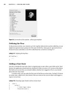
For example, in Figure 9−1, RouterB's successor to reach NetworkA is RouterA, because the cost to reach
NetworkA is 2, which is lower than going through RouterC, which is 3. However, if the metric of the link
between RouterA and RouterB changed from 1 to 20, RouterC would meet the feasibility condition and
become the successor.
349
Figure 9−1: EIGRP terminology
Feasible successor: The feasible successor is a neighboring router that the destination can be reached
through, but is not used because the cost to reach the destination is higher than via a different router. The
feasible successor can be thought of as having the next best route to a destination.
Feasible successors are kept in the topology table and are used as backup routes. For example, in Figure 9−1,
RouterB's feasible successor to reach NetworkA is RouterC. RouterC has a route to NetworkA — however, it
is not the least cost path and therefore is not used to forward data.
Feasibility condition: The feasibility condition is used to prevent routing loops. In order for the feasibility
condition to be met, the route must be advertised from a neighbor that is downstream with respect to the
destination. The cost to reach the destination must be less than or equal to the cost of the route that is currently
being used in the routing table. If the feasibility condition is met, the neighbor becomes the successor. For
example, in Figure 9−1, if the link between RouterB and RouterA were to fail, RouterA would no longer be
the successor. RouterC would move from being the feasible successor to the successor. If the link between
RouterA and RouterB became active again, RouterA would take over as successor because it meets the
feasibility condition. It is downstream from NetworkA and its cost to reach NetworkA is less than RouterC
cost to reach NetworkA.
Active state: When the router loses its route to a destination and no feasible successor is available, the router
goes into active state. While in active state, the router sends out queries to all neighbors in order to find a
route to the destination. At this time, the router must run the routing algorithm to recompute a new route to the
destination.
Passive state: When the router loses its successor but has a feasible successor, it goes into passive state.
Hello: Hello packets are exchanged between neighboring routers. As long as hello packets are received, the
router can determine that the neighbor is alive and functioning.
ACKs: Acknowledgementpackets are sent by the router to acknowledge the receipt of update packets.
Update: Update packets are used by the router to send routing information between neighbors. Update
messages are sent if the metric of a route changes or when a router first comes up.
Query: When the router loses its route to a destination and no feasible successor is available, the router goes
into active state. While in this active state, the router sends out query packets to all neighbors for a particular
destination. The router waits for a response back from all neighbors before starting the computation for a new
successor.
Replies: Replies are sent in response to queries. The reply contains information on how to reach a
destination. If the queried neighbor does not have the information requested, it sends queries to all its
neighbors.
350
Technology Overview
When an EIGRP−enabled router first comes online, it sends hello packets out all EIGRP−enabled interfaces,
using multicast address 224.0.0.10. The hello packets are used for two things: discovering neighboring routers
and, after the neighbor are discovered, determining if a neighbor has become unreachable or inoperative.
Once a new neighbor is discovered via the hello packet, the router records the IP address and interface that the
neighbor was discovered on. The router then sends an update containing all of the routes that it knows about
to the neighbor, and the neighbor does the same. This information is stored in the EIGRP topology table.
Subsequently, hello packets are sent out every 5 seconds, or every 60 seconds on low−speed NBMA
networks. The hello packets allow the router to discover loss of its neighbor dynamically and quickly. If a
hello packet is not received from the neighbor router before the expiration of the HoldTimer, the neighbor is
declared down. At this point, the neighbor adjacency is deleted and all routes associated with that neighbor are
removed.
The topology table includes the router's metric to reach the destination as well as the neighbors metric to reach
the destination. The DUAL algorithm uses the topology table to find the lowest metric loop free path to each
destination. The next−hop router for the lowest−cost path is referred to as the successor and is the next−hop IP
address that is loaded in the routing table. The DUAL algorithm also tries to find a feasible successor, or the
next−best route, which is kept in the topology database.
If the router loses its successor and a feasible successor is available, no route recomputation is necessary. The
router simply makes the feasible successor the successor and adds the new route to the routing table,
remaining in a passive state. However, if no feasible successor is available, the router goes into active state for
the destination network and recomputation for the route is necessary.
While the router is in active state, it sends a query packet out to all EIGRP−enabled interfaces, except the
interface the successor is on, inquiring if the neighbor has a route to the given destination. The neighbors
respond and notify the sender if it has a route to the destination or not. Once all replies are received, the router
can than calculate a new successor. If the neighbor receiving the query packet was using the sender to reach
the destination network (as its successor), it will query all of its neighbors for a route to the destination. The
queried neighbors go through the same process. This creates a cascading of queries through the network,
searching the network for a path to the destination.
As long as EIGRP has a feasible successor, no recomputation is necessary. This prevents the router from
having to use CPU cycles and also speeds up convergence. Routers that are not affected by topology changes
are not involved in recomputations.
EIGRP Metrics
The EIGRP metric is a 32−bit number, which is calculated using bandwidth, delay, reliability, loading, and
MTU. Calculating the metric for a route is a two−step process using the five different characteristics of the
link and the K values. The K values are configurable, but this is not recommended. The default K values are
K1 = 1, K2 = 0, K3 = 1, K4 = 0, and K5 = 0.
Metric = K1*Bandwidth + (K2 * Bandwidth)/(256 − load) + K3*Delay1.
If K5 is not equal to zero, take the metric from step 1 and multiply it by[K5/(reliability + K4)]. If K5
is zero, ignore step 2.
Metric = Metric * [K5/(reliability + K4)]
2.
As shown above, Cisco sets K2, K4, and K5 to zero. This leaves only two variables to compute the EIGRP
metric (bandwidth and delay). Since three of the K values are zero, the formula reduces to:
Metric = Bandwidth + Delay
351
The bandwidth is derived by finding the smallest of all bandwidths in the path to the destination and dividing
10,000,000 by that number.
Delay is found by adding all of the delays along the paths and dividing that number by 10. The sum of the two
numbers is then multiplied by 256. This equation can be written as:
Metric = [(10,000,000/min bandwidth) + (SUM(interface delay)/10)] * 256
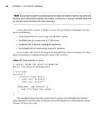
Let's look at Figure 9−2 and determine what the metric is to reach network 1.0.0.0 from RouterB.
Figure 9−2: EIGRP metric
Use the show interface command on each router to determine what the bandwidth and delay is for each
interface.
RouterB#show interfaces S0/0
Serial0/0 is up, line protocol is up
Hardware is QUICC Serial
Internet address is 192.1.1.1/24
MTU 1500 bytes, BW 1544 Kbit, DLY 20000 usec, rely 255/255, load 1/255
Encapsulation HDLC, loopback not set, keepalive set (10 sec)
Last input 00:00:02, output 00:00:02, output hang never
Last clearing of "show interface" counters never
Input queue: 0/75/0 (size/max/drops); Total output drops: 0
Queueing strategy: weighted fair
Output queue: 0/64/0 (size/threshold/drops)
Conversations 0/3 (active/max active)
Reserved Conversations 0/0 (allocated/max allocated)
5 minute input rate 0 bits/sec, 1 packets/sec
5 minute output rate 0 bits/sec, 1 packets/sec
155 packets input, 10368 bytes, 0 no buffer
Received 80 broadcasts, 0 runts, 1 giants, 0 throttles
5 input errors, 1 CRC, 2 frame, 0 overrun, 0 ignored, 1 abort
246 packets output, 13455 bytes, 0 underruns
0 output errors, 0 collisions, 910 interface resets
0 output buffer failures, 0 output buffers swapped out
154 carrier transitions
DCD=up DSR=up DTR=up RTS=up CTS=up
RouterA#show interfaces e0/0
Ethernet0/0 is up, line protocol is up
Hardware is AmdP2, address is 00e0.1e5b.25a1 (bia 00e0.1e5b.25a1)
MTU 1500 bytes, BW 10000 Kbit, DLY 1000 usec, rely 243/255, load 1/255
Encapsulation ARPA, loopback not set, keepalive not set
ARP type: ARPA, ARP Timeout 04:00:00
Last input never, output 00:00:08, output hang never
Last clearing of "show interface" counters never
Queueing strategy: fifo
Output queue 0/40, 0 drops; input queue 0/75, 0 drops
5 minute input rate 0 bits/sec, 0 packets/sec
5 minute output rate 0 bits/sec, 0 packets/sec
0 packets input, 0 bytes, 0 no buffer
Received 0 broadcasts, 0 runts, 0 giants, 0 throttles
0 input errors, 0 CRC, 0 frame, 0 overrun, 0 ignored, 0 abort
0 input packets with dribble condition detected
6 packets output, 1071 bytes, 0 underruns
6 output errors, 0 collisions, 2 interface resets
352
0 babbles, 0 late collision, 0 deferred
6 lost carrier, 0 no carrier
0 output buffer failures, 0 output buffers swapped out
To reach network 1.1.1.0 from RouterB, a packet will cross the serial interface between RouterA and RouterB
and the Ethernet interface on RouterA. Since the lowest bandwidth is used for the calculation, the bandwidth
of the serial interface is used.
Metric = [(10,000,000/BW Serial link) + ((delay on serial link + delay on
the Ethernet link)/10)] * 256
Metric = [(10,000,000/1544) + ((20000 + 1000)/10)] * 256
Metric = 2195456
Lets take a look at the routing table on RouterB and see if our calculations are correct.
RouterB#show ip route
Codes: C − connected, S − static, I − IGRP, R − RIP, M − mobile, B − BGP
D − EIGRP, EX − EIGRP external, O − OSPF, IA − OSPF inter area
N1 − OSPF NSSA external type 1, N2 − OSPF NSSA external type 2
E1 − OSPF external type 1, E2 − OSPF external type 2, E − EGP
i − IS−IS, L1 − IS−IS level−1, L2 − IS−IS level−2, * − candidate default
U − per−user static route, o − ODR
Gateway of last resort is not set
D 1.0.0.0/8 [90/2195456] via 192.1.1.1, 00:21:50, Serial0/0
C 192.1.1.0/24 is directly connected, Serial0/0
IOS Requirements
EIGRP first became available in IOS 9.21; however, EIGRP was significantly enhanced in releases 10.3.(11),
11.0(8), and 11.1(3). All Labs were performed using IOS 11.2.
Commands Discussed in This Chapter
debug eigrp fsm•
debug eigrp packet•
debug ip eigrp•
ip hello−interval eigrp autonomous−system−number seconds•
ip hold−time eigrp autonomous−system−number seconds•
network network−number•
no ip split−horizon eigrp autonomous−system−number•
passive−interface type number•
router eigrp autonomous−system number•
show ip eigrp interfaces [interface] [as−number]•
show ip eigrp neighbors [type number]•
show ip eigrp topology autonomous−system−number•
show ip eigrp traffic autonomous−system−number•
show ip protocols•
traffic−share [balanced | min]•
variance multiplier•
353