CCIE Professional Development Large-Scale IP Network Solut phần 2 pps
Bạn đang xem bản rút gọn của tài liệu. Xem và tải ngay bản đầy đủ của tài liệu tại đây (593.47 KB, 49 trang )
51
Before fully explaining how subnetting is performed, it is necessary to define subnet masking.
Recall that the network portion of the address cannot be changed. For a router to decide what
part of the address is the network and what part is the host, a 32-bit number is used to mask out
each portion.
This mask performs a logical AND operation with the IP address. Wherever the mask is binary
one, it is considered the network portion; when the mask is zero, it is considered the host. A zero
in the network portion tells the router not to consider this part of the network during routing
decisions (see Figure 2-5).
Figure 2-5. Subnetting Using the Logical AND Operation
Subnetting is performed by borrowing bits from the host portion of the address, and then using
them to indicate different segments on the network. A network administrator can borrow any
number of bits from the host portion, as long as a few bits are left available to assign host
addresses.
NOTE
Subnetting extends the network portion of the assigned address to accommodate all physical
segments of a network.
Subnetting Example
In network 131.108.0.0, suppose that you want to perform eight-bit masking of the class B
network. Recall that the first two bytes cannot be altered in a class B network. Therefore, to
perform subnet masking, you must borrow bits from the third byte and use it completely.
As mentioned earlier, subnet masking is performed by borrowing bits from the host portion of the
assigned network address, which assigns more routable network addresses within the assigned
network address. For subnet masking, you would perform a logical AND operation between the
network number and the mask assigned, as shown here:
1 ANDed with 1 = 1
1 ANDed with 0 = 0
52
For eight-bit masking, you can further divide the network into smaller segments to produce the
following:
^8
2 - 2 = 256 - 2 = 254 subnets
All zeros and all ones signify the broadcast address so that they usually cannot be assigned as
the subnet, but Cisco Systems does allow subnet zero to be used as a subnet address. To
enable the subnet zero as an IP subnet, you must use the ip subnet zero command:
ip subnet zero
This should be done carefully to ensure that there are no old hosts that do not understand subnet
zero as the broadcast address. Cisco leaves the choice to the network administrator. If the
administrator is sure that all hosts in the network do not treat subnet zero as the broadcast
address, this additional subnet can be used on the network.
Subnetting is completed between the network number and the subnet mask by a logical AND
operation:
131.108.0.0
255.255.255.0
When a logical AND is performed between the network numbers, the third byte is advertised as
the network portion. Recall that anything ANDed with one yields the same number. If you assign
an IP address of 131.108.1.1 to an interface, the result, after performing the logical AND with the
mask, is 131.108.1.0—anything ANDed with zero yields zero.
Subnetting is performed to assign addresses to different segments of networks, as well as to
isolate the broadcast domains. It also provides more flexibility to a network.
On the host portion of each subnet, there is a maximum of 254 hosts. Remember, however, that
there are eight bits left for the host portion because the network was subnetted after borrowing
eight bits from the assigned class B network address. Because eight bits are left for the host
portion, there are 256–2 addresses left for each host per subnet. You cannot use all zeros and all
ones in an address, which disqualifies two addresses out of the 256 host addresses.
Variable-Length Subnet Masking
With eight-bit masking, there are 254 subnets and 254 hosts per subnet. This model works well
on transit broadcast networks, in which a large number of hosts share a common media. As
shown in Figure 2-6, the serial line needs only two addresses to assign an address with a
subnet mask of /24. Therefore, leaving space for 254 hosts is a waste of address space.
53
Figure 2-6. VLSM for Point-to-Point Links
Address waste is a serious problem in today's networks. Obtaining an IP address is difficult
because of constant growth and increasing numbers of users. Aggressive effort is required to
spare address space from being used inappropriately. This issue will be discussed further in the
next section, "Classless Interdomain Routing."
For this reason, you should perform variable-length subnet masking (VLSM) with point-to-point
networks. VLSM grants transit broadcast networks a large number of bits for the host portion, and
only allows the point-to-point network to use two bits for the host portion.
NOTE
Using a different mask for several types of media within the same major network is called
variable-length subnet masking.
You can subnet further for the serial link so that each link has only two addresses to assign to it—
one for each end of the link's connection. For example, suppose you wanted to further subnet the
131.108.10.0 subnet. You know that the original subnet mask was the eighth bit in the third octet.
For the serial point-to-point connection, you can perform additional masking in the fourth octet, to
essentially create a subnet of a subnet.
As shown in Figure 2-7 depicting serial links, you can use the same third octet value of two and
further subnet the fourth octet. Figure 2-7 shows the new subnets. The original subnet of
131.108.2.0/24 is now further divided into additional subnets of 131.108.2.0/30–
131.108.2.252/30.
Figure 2-7. Introduction of CIDR and Route Aggregation
54
If you borrow six bits from the fourth octet and leave two bits for the host portion, the result is as
follows:
^6
2 - 2 = 64
In this case, the serial line addresses are 131.108.2.0 and 255.255.255.252, and the host
addresses are 131.108.2.1 and 131.108.2.2. You cannot assign addresses of 131.108.2.0 and
131.108.2.3 as the host address because they become the broadcast address for this subnet.
This way, you then can reach 131.108.2.252.255.255.252.0 with the host addresses of
131.108.2.253 and 131.108.2.254. Similarly, you cannot assign host addresses of 131.108.2.252
and 131.108.2.255 because they are the broadcast address for this subnet.
Classless Interdomain Routing
As the popularity of the Internet has grown, it has become the global media for the transfer of
information.
However, as popularity increased, new problems continued to appear. Small organizations
applied for IP addresses, but providing them all with a class A or class B address was not
feasible. Instead, these organizations were assigned class C addresses, or, in a large number of
cases, multiple class Cs. With such a large distribution of IP addresses, the routing table on the
Internet began to grow exponentially. This is the reason CIDR entered the arena.
The following issues led to CIDR:
• Lack of midsize address space and exhaustion of the class B network address space.
Class C is quite small (with 254 hosts), and class B is relatively large (with 65,534
addresses).
• Growth of Internet routing tables.
• Eventual exhaustion of the 32-bit IP address space.
55
It became evident that the first two problems needed to be addressed immediately. This led to the
proposal of RFC 1519, which prompted slower growth of the Internet routing table by condensing
groups of network addresses that fell within close range (called route aggregation).
Route aggregation is performed similar to masking, which led to its other name, supernetting.
With CIDR, the masks in the assigned address are grouped into one update. If an ISP holds an
address range for several class C networks, it does not need to advertise all the specific
networks. The ISP simply can send one update by supernetting them.
NOTE
Route aggregation is the grouping of contiguous class C or class B networks into one update.
As an example of route aggregation, assume that ISP A owns class C networks from 201.1.0.0 to
201.1.127.0. Instead of the ISP advertising all the class C networks, it can group them into one
update and advertise a single supernet network. Supernetting helped significantly slow the growth
of routing tables on the Internet routers.
As shown in Figure 2-7, ISP A does not need to advertise all the specific routes from its
customer to the neighboring ISP B. Instead, ISP A can send only a single route to all its
neighboring ISPs because it can target specific customers. The neighboring ISPs only need to
forward traffic to ISP A for the range of networks.
IP Routing
In the section on subnetting, you learned how a network is divided into smaller groups known as
subnets. Each subnet is given an individual identity. All subnets need to be advertised by an
algorithm within the autonomous system, and the network as a whole must be advertised outside
the system.
To propagate the network within the autonomous system and beyond, routing protocolsare used.
Routing protocols are divided into two types: First, Interior Gateway Protocols (IGPs) are used to
propagate routing information within an autonomous system. Second, Exterior Gateway Protocols
(EGPs) are used to pass routing information between autonomous systems.
Routing protocols running on the Internet include Routing Information Protocol (RIP), Open
Shortest Path First (OSPF), and Intermediate System-to-Intermediate System (IS-IS). All these
protocols are standards-based. In addition, both the Interior Gateway Routing Protocol (IGRP)
and the Enhanced IGRP are Cisco-proprietary protocols. The only EGP presently on the Internet
is BGP, and the current version is four. Each of these protocols is briefly introduced in the
following sections.
RIP
RIP is a distance-vector protocol that uses the Balman Ford algorithm to compute the shortest
route to the destination. It is based on hop count, and does not have the capability to detect real-
time parameters for making proper decisions to reach a destination. This protocol also has a hard
limit of 15 hops, which a network cannot exceed. For more information about RIP, see Chapter
6, "Routing Information Protocol," and Chapter 7, "Routing Information Protocol
Version 2."
56
IGRP
IGRP is also based on distance-vector routing. Cisco developed this protocol in response to RIP's
shortcomings—for example, routers ignore a better bandwidth route in favor of a shorter hop
path.
IGRP has more intelligence to make routing decisions than RIP. It relies on composite metrics of
load, reliability, delay, bandwidth, and MTU. It does not have the 15-hop limit—an IGRP network
can use up to 254 hops, thereby increasing the dimension of the network.
Enhanced IGRP
Enhanced IGRP is an advanced distance vector. Unlike RIP and IGRP, this protocol ensures that
updates are not propagated beyond the affected nodes, ensuring that the entire network is
unaffected. This protocol uses diffuse update algorithm (DUAL) to achieve rapid, loop-free
convergence. Every router maintains a neighbor table, as well as the relevant information
received from the neighbor. For more information on Enhanced IGRP, see Chapter 8,
"Enhanced Interior Gateway Routing Protocol."
OSPF and IS-IS
OSPF and IS-IS are both link-state protocols; each router within an area maintains an identical
database. Every router advertises all its connected functional links after the information is
received in the database. Then, the SPF algorithm is executed to find the shortest path to the
destination.
BGP
BGP exchanges routing information between autonomous systems. It is called a path-vector
protocol because it carries path information from the source, and attaches all the systems that the
route has traversed. This path information is used to detect routing loops. As networks grow and
large organizations merge, BGP is increasingly moving into enterprise backbones because of its
scalability. BGP was designed to handle routing updates and route processing for the dynamic
Internet environment.
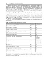
Summary
In this chapter, you learned the fundamentals of IP and its addressing structure. IP can
communicate across any set of interconnected networks, but is not a reliable datagram service; it
is a best-effort delivery. An IP address is 32 bits, which includes a network address and a host
address.
You also learned about subnets, subnet masking, variable-length masking, and why they are
necessary. Subnets provide flexibility to a network by dividing a large network into smaller units,
so that the entire network is not restricted by one network address. Subnet masking is performed
by borrowing bits from the host portion of the assigned network address, so that more routable
network addresses may be assigned within the network address. Variable-length masking is
crucial for preserving valuable address space and to allow continued growth of a network.
57
Another area covered in this chapter is Classless Interdomain Routing. CIDR controls the size of
Internet routing tables. It assists the ISP environment by limiting the number of routes advertised,
which is done by condensing the number of contiguous prefixes that ISP must advertise.
Finally, you were introduced to the two types of major routing processes currently used on the
Internet: Interior Gateway Protocols and Exterior Gateway Protocols. IGPs include RIP, OSPF,
IS-IS and EIGRP; EGPs include only BGP. You will read about each of these in more depth in the
following chapters.
Review Questions
1:
How long is an IP address?
2:
When is the best time to perform subnet masking? When is not good practice to
use it?
3:
What is route aggregation? When should it be utilized?
Answers:
1:
How long is an IP address?
A:
An IP address is 32 bits long and is divided into four octets. Each octet is
separated by a dotted decimal, as in 131.108.1.1.
2:
When is the best time to perform subnet masking? When is not good practice to use it?
A:
Subnet masking is necessary for any IP network, even when you have a single
interface and cannot attach thousands of hosts. If you have a large number of
hosts in your network, you should subnet to separate broadcast domains.
3:
What is route aggregation? When should it be utilized?
A:
Route aggregation deals with groupings of contiguous addresses. You should
perform it as a regular practice whenever you have a contiguous block of
addresses, or major nets that are all behind a certain router. You should remove
unnecessary routing information, so that it is not sent where it is not required.
For Further Reading…
RFC 791
Stevens, W. Richard. TCP/IP Illustrated, Volume 1. Reading, MA: Addison-Wesley,
1994.
58
Chapter 3. Network Technologies
This chapter provides an overview of current local-area network (LAN), wide-area network
(WAN), and metropolitan-area network (MAN) technologies, emphasizing their use in deploying
IP networks. In particular, you will learn about the following:
Packet, circuit, and message switching
This section introduces these three switching paradigms and discusses how they relate to IP
networks.
Local-area networks and technologies
You will read about the difference between token passing and collision-detection technologies.
Then, we describe why Ethernet has become a ubiquitous form of LAN technology. Finally, we
introduce the basic operation of IP over Ethernet.
Wide-area networks and technologies
This section contrasts serial Time Division Multiplexing (TDM) for leased lines, Frame Relay,
ATM, and Packet over SONET. We describe the main benefits and drawbacks of these
technologies, as well as their interaction with the Internet Protocol.
Metropolitan-area networks and technologies
In this section, we briefly introduce various MAN technologies, along with our thoughts on the
future direction of MANs.
Packet, Circuit, and Message Switching
The three switching paradigms that you are likely to encounter with IP networks (packet
switching, circuit switching, and message switching) each have their own characteristics and
requirements that you should consider before deciding which one best suits your network. The
sections that follow define these switching paradigm characteristics and requirements.
Packet-Switched Networks
The Internet, and IP networks in general, are packet-switching networks.This means that all data
is segmented into variable-length IP packets, which are then routed across the network as
discrete entities, as shown in Figure 3-1. Each IP packet contains a source and a destination, as
well as mechanisms to detect packet corruption. Routing in IP networks is usually based on an IP
destination address.
Figure 3-1. Packet Switching
59
Packet routers in IP networks are able to detect IP packet errors, but they do not perform error
correction or provide substantial congestion control (Internet Control Message Protocol [ICMP]
source-quench messages are typically ignored by routers and host). These functions are left to
the Transport Control Protocol (TCP) stack that is implemented on the hosts that connect to the
network. While certain WAN technologies may implement error correction and congestion control
in Layer 2, this process is transparent to the IP router. Many experts argue that performing such
functions in Layer 2 can interfere with the performance of TCP, which causes TCP to degrade.
For large IP networks, therefore, it is not advisable to configure any Layer 2 error correction or
congestion control algorithms.
Sequential IP packets do not necessarily follow the same path through the network, although in
stable routed environments they generally should. For example, the situation depicted in Figure
3-1, in which IP packets 1, 2, and 3, take different routes over the network is undesirable. This is
important because performance of the TCP error correction/congestion control is degraded by the
rapid changes in round trip times when packets take multiple routes—it will look like congestion.
Note that load sharing traffic over multiple parallel WAN links is usually not problematic, if the
propagation delay over each link is similar.
IP packets may be fragmented by IP routers to fit inside the maximum transmission unit (MTU)
associated with particular Layer 2 technologies. The packets are re-assembled by the IP host that
ultimately receives packets, rather than being re-assembled by routers. Fragmentation normally
reduces the efficiency of routers and IP hosts alike. For this reason, it is important to avoid
fragmentation within your network in most cases. Note that most modern TCP applications also
set the Don't Fragment-Bit in the header and are using the Path-MTU-Discovery mechanism
(described in RFC 1191) to automatically detect the maximum possible path MTU size.
Because most host IP implementations usually source IP packets that require routing with a
length of 512 bytes, fragmentation is generally not an issue in networks employing common WAN
or LAN technologies that support much larger frame sizes. It is worth noting that the ATM
Adaptation Layer 5, usually via hardware assisted code, segments the IP packets into cells. It
then re-assembles them in the full IP packet prior to routing to other media. Therefore, IP
fragmentation is not an issue in ATM networks, providing the reassembly buffer at the remote end
of the ATM cloud matches (or is at least smaller than) the MTU sizes used by other WAN or LAN
technologies in the network. Packet over SONET technologies are even more desirable, because
the segmentation function and associated cell tax is completely avoided.
60
NOTE
Cell tax refers to the relatively low ratio of data payload (48 bytes) to header size (5 bytes) in an
ATM cell. Compare this with Ethernet frames, in which the ratio can be as high as 1500:26. While
cell tax may not be in issue for applications that generated data in small discrete quantities, for
applications involving bulk data transfer (such as downloading images), cell tax leads to a
significant decrease in useful data throughput compared with other technologies operating at the
same wire speed.
A packet-switched IP network, in conjunction with careful provisioning and congestion control
techniques that are cognizant of TCP, offers extremely scalable technology for supporting a wide
range of both non-real and real-time applications. This scalability and flexibility is causing the
communications world to focus on the use of IP networks to provide the traditional "Internet"
applications, as well as applications that were traditionally carried by circuit-switched telephone
networks. IP packet switching is necessary for many large corporations and progressive carriers
as the underlying technology for large networks of the future.
Circuit-Switched Networks
Packet-switched networks fundamentally differ from circuit-switched networks. As shown in
Figure 3-2, a connection must first be established between two end hosts in order for them to
communicate in a circuit-switched network. This can be achieved by i n-band signaling
(call_setup) within a circuit—in other words, the end host transmits a set of signals that allows the
circuit to be extended, hop-by-hop, through the network. Alternatively, as in the case of the
Integrated Services Digital Network (ISDN), the circuits can be established with the assistance of
a second "control-plane" network, which is usually a lower-bandwidth, packet-switched network,
and carries only the call setup packets. This requirement for a pre-established circuit prior to
communication is in contrast to IP's "connectionless" paradigm, in which a host can begin
transmitting to any other host on the network at any time.
Figure 3-2. Circuit Switching
Also, unlike packet-switched networks, once the circuit is established, all data flows over the
same path through the network. In Figure 3-1, all data associated with the call passes through
nodes A, B, and C; and follows the symetrical return path. Therefore, the parameters of the
session, such as delay and bandwidth, are fixed—this is both an advantage and a limitation to
61
end-user applications. The advantage of fixed delay for real-time applications is guaranteed
delivery at regular intervals. For example, in telephone calls, this is important for smooth
reproduction of conversations. The limitation, in terms of bandwidth, is that some applications
may use all of the available bandwidth within their circuit, whereas others may use much less.
The application that consumes more bandwidth cannot contribute its spare bandwidth to the
application that requires less bandwidth. The result of this limitation is poor performance in
environments where bandwidth requirements change over time. For example, when you are
downloading or reading Internet Web pages, the process becomes frustratingly slow. However,
given their predictable delay and bandwidth characteristics, circuit-switched networks are a
convenient choice for fixed-bandwidth, real-time applications such as telephone services.
Message-Switched Networks
Message switching is a technology that overlays packet- or circuit-switched networks. The routing
paradigm is one of "store-and-forward." For example, suppose that, as shown in Figure 3-3,
host X (Source) wants to send a message to host Y (Destination). Assume that host X cannot
send the message directly to host Y because of network congestion, security limitations such as a
firewall, or an outage. Instead, host X will pass the message to another node, C, that is closer to
the ultimate destination, host Y. Node C will then store, and, at some later time, forward the
message to host Y. Node C may perform some error-checking or other functions on the message
prior to forwarding it to host Y.
Figure 3-3. Message Switching
Routing e-mail over an IP packet network is an example of message switching. If one host needs
to send an e-mail message to another host that is unreachable, it can use the Domain Name
System (DNS) to find alternative mail-exchangers for the unreachable host. Such hosts will
accept and store the message until the ultimate destination is again on-line. Clearly, message
switching is unsuitable for time-sensitive or real-time applications.
62
Local-Area Networks and Technologies
Local-area network ( LAN) technologies, as the name suggests, are extremely localized, covering
a small geographic area up to only a few thousand meters. For example, they can connect
computers within or between buildings, or within a particular department, such as Accounting or
Marketing. Whenever there is a situation in which you are able to install your own physical media
to connect peripherals, workstations, and terminals, you would employ LAN technologies.
Because of their limited range, LANs will not perform well where there is a large distance
between sites.
LAN technologies usually operate with the assumption of a single physical media shared among
many computers. However, the sharing algorithms are divided into two categories: those sharing
algorithms that use collision detection, such as Ethernet; and those sharing algorithms that
employ a token to arbitrate access to the LAN media, such as Token Ring and Fiber Distributed
Data Interface (FDDI). Most technologies employ error detection; however, the most commonly
used technologies do not provide error correction. The error rate on LANs, compared to WANs, is
low in the "normal" operating environments of offices and other similar environments.
LANs: The Heart of the Internet
It is a little-recognized fact that LAN technologies, because of their low price/speed ratio, still form
the "heart" of the Internet—the place in which large numbers of major providers meet to
exchange traffic with other providers. The original MAE-East and Federal Exchange points were
based on Ethernet until they were later upgraded to FDDI and then switched FDDI, using
Gigaswitches from Digital.
ATM was used at one or two public exchange points. However, more recently, Gigabit Ethernet
switches are looking to be a promising technology. Providers establishing private peering at a co-
location facility may use LAN technologies to connect their routers, rather than using ATM or
Packet over SONET interfaces, which are more expensive in terms of price as well as router slot
space.
Ethernet
Although Ethernet was invented in the 1970s, a commercially available product did not become
widely used until the early to mid-1980s. From that point on, however, Ethernet technology
experienced explosive growth, which continues today.
The operation of Ethernet is relatively simple. A broadcast medium, such as coaxial cable or an
interconnected twisted pair, connects all hosts. A host or a router on an Ethernet LAN may begin
transmitting only if no other messages are currently being transmitted on the media. There is a
period called the collision window, related to the length of the Ethernet media, in which two hosts
may both begin transmitting without hearing each other. Eventually, however, the signals will
collide. Because of signal corruption during reading, both hosts will recognize that a collision has
occurred. Both stations then will execute a back-off algorithm, causing them to reattempt their
transmissions randomly at a later time. All being well, further collisions will be avoided.
Although coaxial cable was Ethernet's original chief support, this has more recently become
optical fiber for links between buildings, and Category 5 unshielded twisted-pair (UTP) within
buildings. As shown in Figure 3-4, a typical installation may consist of a hierarchy of hubs and
switches, with a router at the highest level providing WAN connectivity or LAN segmentation.
Figure 3-4. 10BaseT/100BaseT Ethernet Topology
63
The theoretical data transmission rate of Ethernet is 10 Mbps. In practice, the data rates
observed could vary widely with the number of computers on the LAN, their distribution and
length of the LAN media, and the nature of the data flows. Excessive collision can slow the
usable data rate to a crawl. This has led many users to embrace the 100 Mbps token passing
technology of FDDI. However, with the introduction of Fast Ethernet technologies (100 Mbps) and
Gigabit Ethernet technologies (1000 Mbps), the LAN market has settled on these as the end-user
technologies. In some cases, Asynchronous Transfer Mode (ATM) switches are used to connect
large Ethernet switching hubs.
The interaction between Ethernet and IP is relatively simple. All Ethernet interfaces, which may
be on computers or routers, are assigned a unique six-octet Media Access Control (MAC)
address. When one IP host needs to send an IP packet to another host on a LAN, the ARP
protocol requests the MAC address that corresponds to a particular host. As a result of
standardization, two encapsulations of IP in Ethernet frames are currently being used:
• Ethernet II—
Specified in RFC 984
• IEEE 802.3—
Specified in RFC 1042
Usually, only routers listen to and convert between the two types. Modern Ethernet cards and
Fast Ethernet components use only the latter.
64
Token Passing Technologies, which we'll discuss next, also employ ARP to resolve IP addresses
into MAC addresses.
Token Passing Technologies
The advantage of token passing technologies is predictable degradation as utilization increases.
A token is a small frame containing control information, and is passed from one computer to
another. It allows a network device to transmit data onto the network. Each computer may absorb
the token for a certain maximum period of time, during which it may transmit any packets it may
have. The data packets propagate around a ring until they are read by the destination. Then, they
continue cycling the ring until they are removed from the ring by the original source of the packet.
Figure 3-5 illustrates a typical Token Ring topology. One or more Multistation Access Units
(MAUs) are connected in a ring configuration. Each MAU adds one or more hosts or routers into
the ring. The MAU may detect host failure and remove it from the ring.
Figure 3-5. Token Ring Topology
FDDI, a LAN standard defined by the American National Standards Institute (ANSI) in X3T9.5,
uses dual-ring architecture to provide redundancy. FDDI allows multiple packets plus a token on
the ring at any one time, whereas Token Ring (without the Early-Token Release Feature) allows
only one packet—each station holds the token until it removes any packets it has transmitted
from the ring. By adjusting the token holding time on a per-host basis, it is possible to share
bandwidth fairly equally between all computers, and to intentionally allocate certain hosts more
bandwidth than others. In addition, by using dual physical rings, hosts can "wrap around" physical
breaks in the ring. A host may connect to one (Single Attach Station) or both (Dual Attach
Station), according to reliability requirements. FDDI and variants on FDDI were also proposed as
the basis for MAN technologies.
Figure 3-6 illustrates a typical FDDI topology. The left configuration demonstrates a number of
DASs and a router connected in a physical ring. The right configuration shows a number of SASs
(including a router) connecting to a central switch (or hub).
Figure 3-6. FDDI Topology
65
Ethernet versus Token Passing Technologies
Token Ring, which is a token-passing LAN developed and supported by IBM, enjoyed enormous
popularity during the days of IBM's Systems Network Architecture (SNA) networks, which
developed in the 1970s. FDDI, a 100 Mbps optical fiber-based system, also was briefly popular
due to its substantial speed advantage over the contemporary 10 Mbps Ethernet and its immunity
to electrical interference. FDDI's largest drawback was the high cost of optical components.
However, the lower cost and "plug-and-play" nature of 10 Mbps Ethernet over UTP (10BaseT) led
to a massive foothold in the market, despite its speed limitation. This allowed higher speed
implementations of the Ethernet link layer protocol, and large-scale deployment of "switched"
LAN segments. It became more expedient to connect 10 Mbps and 100 Mbps "Fast Ethernet"
LANs using switches. If UTP was used as the media, both speeds could run on the same media,
and a single switch supported hosts of different speeds through an auto-negotiation process
between switch and host.
Wide-Area Networks and Technologies
Wide-area network ( WAN) technologies are characterized as networks covering a broad
geographical area. These technologies use common carrier facilities. On a seven-layer model,
they operate on the physical, data link layer. WANs are divided into three types of links:
• Point-to-point(leased line)—
There are several common protocols used in these links—the most common are Point-to
Point Protocol (PPP), Synchronous Data Link Control (SDLC), and High-Level Data Link
Control (HDLC). Because point-to-point links and their protocols are the most widely
used, we discuss them in more detail in the sections that follow.
• Packet-switching—
The packet-switching protocol finds the most efficient paths for routing packets, and
multiple connections are allowed to share a communications channel. It uses statistical
multiplexing, ATM, Frame Relay, X.25, and Switched Multimegabit Data Service (SMDS).
Later in this chapter, we will discuss the two most commonly used packet switched
technologies—ATM and Frame Relay.
66
• Circuit-switching—
Circuit-switching protocols are used most often in the telephone industry, in which a
dedicated physical circuit path between sender and receiver is necessary. ISDN is a
commonly used circuit-switching protocol.
Point-to-Point Links
Point-to-point links, as the name indicates, provide a pre-established path between two points.
Connection is established through a carrier network, which is a permanently defined circuit
between two points on the customer network. These circuits are dedicated solely for the private
use of the customer. As mentioned in the preceding list, the most commonly employed protocols
by point-to-point links include SDLC, HDLC, and PPP, as discussed in the sections that follow.
SDLC/HDLC
Other than PPP, there are two types of commonly used protocols for point-to-point links— SDLC
and HDLC. These are synchronous, bit-oriented, full-duplex protocols. HDLC, a derivative of
SDLC, was developed by IBM in the mid-1970s for use in SNA networks. By default, Cisco
employs HDLC framing for synchronous data transfer on point-to-point links.
SDLC supports many link types, and it can be applied in both point-to-point and multipoint
technologies. Two types of nodes are defined—primary and secondary. The primary node
controls the operation of the secondary node, and it polls the secondary nodes with a defined
method. The secondary node can transmit data during this polling process if it has data to be
sent. Figure 3-7 shows the frame format for SDLC.
Figure 3-7. SDLC Frame
67
The frame is bounded by a Flag pattern. The Address field is used for indicating the secondary
node involved for communication. Because primary is always either the source or the destination
of the communication, that is why it is not in the SDLC frame. All the secondaries already know
the primary's address. The Control field in the frame is altered according to the type of SDLC
frame used, as explained in the list that follows.
• Information (I) frames—
Carry upper-layer information and some control information. Send and receive numbers
and poll final (P/F) also does error correction. Send and receive sequences are used to
indicate the frame number being sent and received. The primary node uses the P/F bit to
indicate to the secondary node that it needs immediate response. The secondary node
uses these bits to indicate whether this is the last frame in the response.
• Supervisory (S) frames—
Used to request and suspend the transmission, report on status, and acknowledge the
receipt of I frames. Supervisory frames do not have any data.
• Unnumbered(U) frames—
68
Used for control purposes (that is, to initialize the secondary node, and so forth).
Unnumbered frames are not sequenced.
Because HDLC is a derivative of SDLC, they share the same frame format. HDLC has a few
capabilities that are additional to those in SDLC. For example, SDLC supports only one transfer
mode, whereas HDLC supports three:
• Normal Response Mode (NRM)—
Both HDLC and SDLC use this mode. In this mode of operation, the primary node cannot
communicate unless permitted by the secondary node.
• Asynchronous Response Mode (ARM)—
Unique to HDLC, in this mode, the secondary node can initiate communication without
the permission from the primary node.
• Asynchronous Balanced Mode (ABM)—
Unique to HDLC, in this combined mode, either the primary or the secondary node can
initiate communication without the permission from the other.
Point-to-Point Protocol
Point-to-point links are also connected by using the Point-to-Point Protocol (PPP). Invented in the
1980s, PPP filled the industry's demand for a connection between LAN and WAN. PPP provides
a standard-based protocol to connect point-to-point IP links.
As the name suggests, PPP is used for data transfer across point-to-point serial links. The
protocol has three main components:
• It uses HDLC for the encapsulating datagrams over serial point-to-point links.
• It has an extensible link control protocol to establish, test, and data-link connections.
• It uses several network control protocols for establishing different network layer protocols.
For the operation of PPP connections, the sending station sends Link Control Protocol (LCP)
frames for testing. This configures the data link. After the data link has been established, the
originating station sends Network Control Protocol (NCP) frames for the selection of the network
protocol. After the selected network protocol has been established, packets for the network
protocol can be sent across the link. The link remains active for the protocol unless explicit
messages are sent signaling that the link should be closed.
Packet-Switching Links: Frame Relay
Frame Relay was initially developed by the American National Standards Institute (ANSI) in 1984.
Cisco Systems undertook major redevelopment of Frame Relay in 1990. StrataCom (now part of
Cisco Systems), Northern Telecom, and Digital Equipment Corporation formed a consortium to
focus on the development of Frame Relay technology. This consortium developed some
additional features for the internetworking environment.
Frame Relay is a packet-switching technology that provides a connection between a router and a
packet switch device. A Frame Rely network that provides connection can be either a public
69
network or a privately owned network. To connect a network with a user interface, Frame Relay
creates virtual circuits, which are created by statistically multiplexing many logical connections
over single physical links. Statistical multiplexing provides a more efficient way of using the
available bandwidth.
Frame Relay is capable of managing multiple virtual circuits using HDLC encapsulation between
connected devices. One of the biggest advantages of Frame Relay is its efficient digital design,
unlike its predecessors, such as X.25 (that it essentially replaces), which were developed when
analog technology was used and circuits were unreliable. Instead of having to perform error
corrections, Frame Relay includes the cyclic redundancy check (CRC) called frame check
sequence (FCS), which informs network devices of data corruption so that bad data can be
discarded. This technology leaves error-correction algorithms for the upper-layer protocols.
Because upper-layer protocols are capable of performing explicit flow control per virtual circuit,
this function is not included in Frame Relay. Instead, Frame Relay provides a very simple
notification procedure that signals the user devices when network resources are close to
congestion. This also signals upper-layer protocols to activate the flow control feature when a link
is congested.
Frame Relay provides connection-oriented, data link layer communication. This service is
implemented by using virtual circuits, which are logical, bidirectional connections between the two
end-node devices across the packet-switched network. These virtual circuits are uniquely
identified by a Data Link Connection Identifier (DLCI). A virtual circuit can pass through any
number of switches in a Frame Relay network, as illustrated in Figure 3-8.
Figure 3-8. Frame Relay Connections via Switches
In addition to simplifying the protocol, the consortium specification includes Local Management
Interface (LMI) extensions, which simplified the Frame Relay implementation over large networks.
These extensions deal with number of Frame Relay switches located within a Frame Relay
network. These virtual circuits can be switched virtual circuits (SVCs) or a permanent virtual
circuit (PVC). The LMI extension includes virtual circuit message status, global addressing,
multicasting, and flow control.
70
Packet-Switching Links: ATM
ATM adopts a strategy of segmenting all IP packets into small, 53-byte cells carrying a 48-byte
data payload. The motivation for small cells is based on minimizing packetization delay, which
makes the technology suitable for time-sensitive applications. The motivation for fixed cells is to
allow the switching to occur in hardware, because hardware switching of variably sized frames is
more complex. The choice of small cell size has been a source of debate. Nevertheless, in local
area environments, the low cost/speed ratio of ATM switches makes them attractive. Prior to
Gigabit Ethernet, ATM switches were the only options for LAN operation at hundreds of megabits
per second.
ATM promises scalable bandwidth and quality of service guarantees with minimal cost. It is a cell-
based technology that facilitates development at hardware-level, high-performance switches. An
ATM network consists of ATM switches connected via point-to-point links. ATM supports two
types of interfaces: the User-Network Interface (UNI) and the Network-Node Interface (NNI). The
UNI interface connects the ATM switch with the end system, such as the router or host. The NNI
interface interconnects two ATM switches. Figure 3-9 illustrates a typical ATM network setup.
Figure 3-9. ATM Network Setup via Switches
By nature, ATM networks are connection-oriented, which means that a virtual circuit needs to be
established prior to data transfer. ATM has two basic types of circuit indicators that are used for
setting up the virtual circuit: Virtual Path Identifier (VPI) and Virtual Channel Identifier. Both VPI
and VCI have only local significance across a particular link. ATM operates as follows:
Step 1. The ATM network receives a cell across a particular link on a known VCI or VPI.
Step 2. Switch looks up the connection in the local translation table to determine the outgoing
port and the VCI/VPI value of the connection.
Step 3. Switch sends the cell on the outgoing links.
71
The ATM switch is also relatively simple, due to an external method of organizing the local table
for data transfer. There are two fundamental types of tables: Permanent virtual circuits and
switched virtual circuits.
In WAN environments, in which the "cell tax" is very significant, there is increasing importance
placed on IP Packet Over SONET (POS) solutions.
Circuit-Switching Links: ISDN
Integrated Services Digital Network (ISDN) is used by telephone companies to carry digitized
voice and data over the existing telephone system. ISDN has emerged as one of the leading
technologies for telecommuting and remote office connection into the corporate headquarters.
On the seven layer model, ISDN operates at the physical, data link, and network layers. ISDN
basic rate interface (BRI) provides two barrier channels (commonly referred as B channels). Each
of these B channels carries data at 64 kbps. The D channel coexists along with B channels. The
D channel operates at 16 kbps and is usually used for carrying control information.
The ISDN primary rate interface (PRI) service delivers 23 B channels and one 64-kbps D channel
in the US and Japan with a total bit rate of 1.544 Mbps. In other parts of the world, the PRI
service provides 30 B channels for a total bit rate of 2.048 Mbps.
ISDN consists of three network components: ISDN terminal equipment, termination devices, and
reference points. ISDN terminal equipment has two basic terminal equipment types:
• TE1—
A specialized ISDN terminal that includes computers equipment and phones.
• TE2—
DTE equipment that connects to the ISDN line through a terminal adapter (TA).
ISDN Network Termination Devices are called network termination (NT) devices. There are three
supported NT types:
• NT1—
Treated as a customer premises equipment in North America, elsewhere it is provided by
carrier.
• NT2—
Found in PBXs, this device type provides Layer 2 and Layer 3 functions and
concentration services.
• NT1/2—
Combines the functions of both NT1 and NT2 and is compatible with both NT1 and NT2
devices.
72
ISDN reference points are used for logical interface. Four reference points are defined:
• R reference point—
Defines the logical interface between no-ISDN equipment and TA.
• S reference point—
Defines the reference point user terminal and NT2.
• T reference point—
Located between NT1 and NT2 devices.
• U reference point—
Located between NT1 and line-termination equipment in a carrier network.
Circuit-Switching Links: Synchronous Optical Network
Synchronous Optical Network (SONET) was defined in the 1980s as a standard by which carriers
could build multivendor transport infrastructure. SONET is divided into three areas: Physical,
Payload, and DCC.
SONET uses a frame structure that repeats itself every 125 ms, enables providers to set up a hub
topology rather than just point-to-point connections, and supports a fiber optic ring, which is
created by fiber optics. In case of a failure, a bidirectional ring can be used, which is capable of
rerouting traffic from the affected nodes within a millisecond. This protects providers from service
outages. SONET uses Add-Drop Multiplexers (ADM) to create network protection architectures,
known as Unidirectional Path Switched Rings (UPSR). ADM provides UPSR protection by
multiplexing a tributary onto the two outgoing channels, diversely routed over different fiber paths
to an end node. The UPSR protection system allows multiple elements to be located within a ring.
The UPSR add-and-drop mechanism permits many customers to share traffic across a local-area
network. Many nodes could be added to a UPSR to provide a high level of fiber utilization. Each
remote location can be added or dropped along the path as the ring traverses customer locations.
Metropolitan-Area Networks and Technologies
Around the same time that the IEEE was developing LAN standards and IEEE 802.3, a new
consortium was formed to study metropolitan-area networks (MANs). The consortium's original
intent was to bridge the gap between WAN technologies such as ATM or ISDN, and LAN
technologies such as Ethernet or local ATM. The original design goals were to provide a shared,
fairly high-speed fiber optic network that was optimized to operate over distances from several
city blocks to approximately 30 miles, about the size of large city.
Distributed Queue Dual Bus
The standard resulting from this IEEE study is numbered 802.6, and named Distributed Queue
Dual Bus (DQDB), which essentially describes both the topology used by the technology, and the
media access mechanism.
73
In this technology, illustrated by Figure 3-10, two optical fiber buses carry communications
between all stations. The buses are unidirectional, and a DQDB station needs to attach to both,
either through a passive or active fiber tap. One bus communicates with upstream stations, and
the other communicates with downstream stations. Therefore, over time, the stations must learn
which stations are upstream or downstream. Otherwise, data must be transmitted on both buses
until the necessary upsteam/downstream intelligence is gained. Although the intent of DQDB was
to operate on high-speed optical fiber such as OC3, it is capable of operating on T1 or DS3 cable
infrastructure. In fact, because of its popularity in the US during DQDB development, a detailed
standard for DQDB over DS3 has been established.
Figure 3-10. DQDB Topology
The Distributed Queue access protocol arbitrates access to the Dual Bus media. The protocol
allows each station to reserve time slots, and supports three levels of priority. A station must
honor the reservations of downstream stations. Therefore, the majority of the Distributed Queue
protocol is concerned with communicating reservations from downstream stations to upstream
stations.
DQDB uses the same fixed 53-octet cell size used by ATM. Physical switching between ATM and
DQDB is therefore relatively simple. In addition, DQDB recognizes both 60-bit ISDN and 48-bit
LAN addressing, enabling the technology to carry both local and wide-area data traffic. In the
latter case, ATM-like segmentation and reassembly of LAN frames is necessary.
Limitations of DQDB
The 802.6 DQDB standard never became popular as a means to interconnect LAN or digital
telephony systems. Within the US, DQDB made a brief appearance as a commercial service in
the form of the Switched Multimegabit Data Service (SMDS). However, in terms of tariff or
capabilities, it never held any real advantage over Frame Relay, and had only marginal
advantage over T1. Moreover, in many ways MANs are based upon the assumption that
customers want to connect LANs at Layer 2. As the communications world began converging on
IP, and as routers became an inexpensive data communications commodity, this assumption
became less valid. Designers of IP networks preferred the simplicity of dedicated, point-to-point,
74
Layer 2 services, because this allowed the IP engineer to determine traffic patterns and fail-over
mechanisms via IP routing protocols. The "shared" nature of SMDS translated to "unpredictable"
in the IP engineer's mind. Although there is nothing to stop SMDS from connecting two routers, in
the absence of a highly differentiated cost (over, say, a T1), there was little to recommend the
MAN technology over traditional TDM services. Today, it is common to see Frame Relay, T1, or
even dark fiber filling the application space originally intended for MANs.
Summary
This chapter provided a brief introduction to the switching network paradigms; and LAN, WAN,
and MAN technologies. IP is a connectionless, packet-switching technology, which allows highly
efficient use of network resources for all users. In LANs, Ethernets at 10, 100, and 1000 Mbps
have become the technology of choice. To a lesser extent, ATM is also used, whereas use of
token-passing technologies such as Token Ring and FDDI is rapidly declining.
In WANs, traditional Time Division Multiplexing (TDM) "leased-line" technologies, such as T1, are
still widely deployed. At speeds in the low Mbps and below, Frame Relay is also widely being
deployed. At higher speeds, Packet over SONET is gaining popularity in the US, and ATM is
widely used in other areas of the world.
Finally, in MANs, DQDB was used briefly as the SMDS service. SMDS offered very little
advantage over the available WAN, or the more-recent, dark-fiber services for the connection of
LANs over distances of less than 30 miles.
This chapter merely introduces these networking technologies to provide the reader with basic
contextual knowledge of data link and physical layer services. Unlike large-scale IP routing, the
published literature on LAN and WAN technologies is vast—for additional information on these
areas, there are many excellent references, which are listed at the end of this chapter.
Review Questions
1:
If a router needs to forward a packet to an IP destination on a LAN, how does it
discover the Layer 2 (MAC) address of the destination?
2:
Do you need a router to connect 10 Mbps Ethernet to higher-speed Ethernet
LANs?
3:
What are the two modes used by HDLC that are additional to the mode used by
SDLC?
4:
What is the cell size of ATM?
Answers:
1:
If a router needs to forward a packet to an IP destination on a LAN, how does it discover the
Layer 2 (MAC) address of the destination?
A:
The Address Resolution Protocol (ARP) is used to broadcast a request for the
75
Layer 2 address associated with a particular Layer 3 address.
2:
Do you need a router to connect 10 Mbps Ethernet to higher-speed Ethernet LANs?
A:
A router can be used and may be desirable to provide a "safety barrier" between
two LANs. This can help LANs to scale. However, the benefit of the various
Ethernet technologies is that they may be connected by simple inexpensive
switches. A single switch may support multiple Ethernet speeds.
3:
What are the two modes used by HDLC that are additional to the mode used by SDLC?
A:
Asynchronous Response Mode (ARM) and Asynchronous Balance Mode (ABM).
4:
What is the cell size of ATM?
A:
53 bytes.
For Further Reading …
Alles, Anthony. ATM Internetworking. San Jose, CA: Cisco Systems Inc., 1995.
Alles, Anthony, and Minoli, Dan. LAN, ATM, and LAN Emulation Technologies. Norwood, MA:
Artech House, 1997.
Black, Ulysses. ATM: Foundations for Broadband Networks. Englewood Cliffs, NJ: Prentice-Hall,
1995.
Black, Ulysses, and Waters, Shareen. SONET T1: Architectures for Digital Transport
Networks.Upper Saddle River, NJ: Prentice-Hall, 1997.
Black, Ulysses. Data Link Protocols. Upper Saddle River, NJ: Prentice-Hall, 1993.
Black, Ulysses. Physical Layer Interfaces and Protocols, Second Edition. Los Alamitos, CA: IEEE
Computer Society Press, 1996.
Cisco Systems, Inc. Introduction to WAN. San Jose, CA: Cisco Systems Inc., June 17, 1999.
Cisco Systems, Inc. The Cisco ISR 3303 Integrated SONET Router. San Jose, CA: Cisco
Systems Inc., 1999.
Dorling, Brian et al. Internetworking over ATM—An Introduction. Upper Saddle River, NJ:
Prentice-Hall, 1996.
Kercheval, Berry. TCP/IP over ATM: A No-Nonsense Internetworking Guide. Upper Saddle River,
NJ: Prentice-Hall, 1998.
Kyas, Othmar. ATM Networks. Second Edition. Boston, MA: International Thomson Computer
Press, 1997.