ccna practical cisco routers phần 3 pps
Bạn đang xem bản rút gọn của tài liệu. Xem và tải ngay bản đầy đủ của tài liệu tại đây (4.38 MB, 39 trang )
7 0
Repeaters
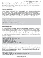
Repeaters take the signal that they receive from network devices and
regenerate the signal so that it maintains its integrity along a longer
media run than is normally possible. Because all media types (copper
cable, fiber optic cable, and wireless media) must deal with attenua-
tion limiting the possible distance between network nodes, repeaters
are a great way to physically enlarge the network.
Because repeaters are Physical layer devices, they don’t examine the
data packets that they receive, nor are they aware of any of the logi-
cal or physical addressing relating to those packets. This means that
placing a repeater on a network doesn’t slow down the flow of infor-
mation on the network to any great degree. The repeater just sits on
the network boosting the data signals received on one particular seg-
ment and passing it back out to another segment on the network as
the data makes its way to its final destination (see Figure 4.2).
PART I Networking Overview
CHAPTER 4 In ternetworking Basics
FIGURE 4.2
Repeaters boost thedata
signal from one network
segment and pass it on
to another network seg-
ment, extending the size
of the network.
7 1
PART I
In tern et working Devices CHAPTER 4
Bridges
Bridges are internetworking devices that operate at the Data Link
layer of the OSI model. This means that they have greater capabili-
ties (networking-wise) than Layer 1 devices like repeaters and hubs.
Bridges are used to segment networks that have grown to a point
where the amount of data traffic on the network media is slowing the
overall transfer of information.
Bridges (which consist of the bridge hardware and some type of
bridge operating system software) have the capability to examine the
MAC address (also known as the hardware address; remember it’s
burned onto the NIC in each computer on the network) on each
data packet that is circulating on the network segments that are con-
nected to the bridge. By learning which MAC addresses are residents
of the various segments on the overall network, the bridge can help
keep data traffic that is local to a particular segment from spreading
to the other network segments that are serviced by the bridge.
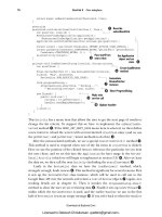
So basically bridges provide a segmentation strategy for recouping
and preserving bandwidth on a larger homogenous network
(homogenous meaning that the entire network consists of a particu-
lar architecture such as Ethernet). For example, you may segment a
larger network using a bridge into three different segments as shown
in Figure 4.3.
Let’s say that a computer on segment A transmits data that is
intended for another computer on segment A. The bridge will exam-
ine these data packets (checking out their source and destination
MAC addresses), determine that they stay on segment A, and discard
the packets. (It doesn’t clear the packets from the network; remem-
ber that Ethernet is a passive architecture where all the nodes on the
network sense the data on the carrier line.) The fact that the bridge
doesn’t forward the packets to the other segments on the network
preserves the bandwidth on those segments (their lines aren’t clut-
tered up by data that isn’t intended for the computers on that partic-
ular segment).
Internetworking with an
Ethernet bent
You will find that as the
various internetworking
devices and internetwork-
ing itself are discussed in
this chapter, much of the
information relates more
directly to Ethernet net-
works than other architec-
tures such as Token Ring
and FDDI. The reason for
this is simple: Ethernet is
the most commonly
employed network architec-
ture, and many internet-
working devices were
devised because of connec-
tivity issues withEthernet
networks. For a wealth of
information on Token Ring
and other LAN technologies
(related to IBM hardware
such as Token Ring and
FDDI NICs), check out the
white papers offered by
IBM on its support Web
site at http://www.
networking.ibm.com/
nethard.html. These
white papers come in
HTML and PDF formats (for
Adobe Acrobat Reader) and
are a great free resource
for network administrators.
A good tutorial on the
basics of FDDI can be
found at http://www.
data.com/tutorials/
boring_facts_about_
fddi.html. Another good
source of networking arti-
cles can be found at
www.cmpnet.com/,
which has links to a large
number of sites that
provide information on LAN
and WAN technologies.
7 2
In another scenario, a computer on segment A transmits data that is
intended for a computer on segment C. Again, the bridge will exam-
ine the MAC addresses of these packets and in this situation it will
forward the packets from segment A to segment C. The bridge is
very specific about where it forwards the packets. No packets will be
forwarded to segment B.
Although bridging might sound like the ultimate answer to maximiz-
ing network throughput, it actually does have some downsides.
Bridges forward broadcast packets from the various nodes on the
network to all the segments (such as NETBIOS and other broad-
casts). Also, in cases in which the bridge is unable to resolve a MAC
address to a particular segment on the network, it forwards the pack-
ets to all the connected segments.
PART I Netwo rking Overview
CHAPTER 4 In ternetworking Basics
FIGURE 4.3
Bridges segmentlarger
networks to keep
segment data traffic
localized.
Repeaters,
concentrators, and
active hubs
Repeaters are also referred
to asconcentrators. Hubs
that have the same signal
boosting capabilities as
repeaters are referred to as
active hubs or multiport
repeaters. All these devices
(no matter what you call
them) operate at the
Physical layer of the OSI
model.
7 3
PART I
In ternet working Devices CHAPTER 4
Switches
Switches are another Layer 2 internetworking device that can be
used to preserve the bandwidth on your network using segmentation.
Switches are used to forward packets to a particular segment using
MAC hardware addressing (the same as bridges). Because switches
are hardware-based, they can actually switch packets faster than a
bridge.
Switches can also be categorized by how they forward the packets to
the appropriate segment. There are store-and-forward switches and
cut-through switches.
Switches that employ store-and-forward switching completely
process the packet including the CRC check and the determination
of the packet addressing. This requires the packet to be stored tem-
porarily before it is forwarded to the appropriate segment. This type
of switching cuts down on the number of damaged data packets that
are forwarded to the network.
Cut-through switches are faster than store-and-forward switches
because they forward the packet as soon as the destination MAC
address is read.
Routers
Routers are internetworking devices that operate at the Network
layer (Layer 3) of the OSI model. Using a combination of hardware
and software (Cisco Routers use the Cisco IOS—Internetwork
Operating System), routers are used to connect networks. These net-
works can be Ethernet, Token Ring, or FDDI—all that is needed to
connect these different network architectures is the appropriate
interface on the router.
Because routers are Layer 3 devices, they take advantage of logical
addressing to move packets between the various networks on the
Internetwork. Routers divide the enterprisewide network into logical
subnets, which keep local traffic on each specific subnet. And because
routers don’t forward broadcast packets from a particular subnet to
all the subnets on the network, they can prevent broadcast storms
from crippling the entire network.
Transparent bridges
build a bridging table
Transparent bridgesare
employed on Ethernet net-
works; they forward pack-
ets (or drop packets that
are part of local segment
traffic) on the network
based on a bridging table.
The bridge builds the table
by sampling the packets
received on its various
ports until it has a com-
plete list of the MAC
addresses on the network
and the particular network
segment that they are pre-
sent on.
Source-routing bridges
Source-routingbridges on
Token Ring networks don’t
work as hard as transpar-
ent bridges on Ethernet
networks. Source-routing
bridges are provided the
path for a particular set of
packets it receives within
the packets themselves.
The bridge only needs to
follow the directions con-
tained in the packets to for-
ward them to the
appropriatesegment.
7 4
Because this book is about routers and routing (specifically Cisco
Routers and the Cisco IOS), the ins and outs of how routers work
and the routing protocols that they use to move packets between
subnets are discussed in more detail in Chapter 5, “How a Router
Works.”
Gateways
Gateways are used to connect networks that don’t embrace the same
network protocol and so protocol translation is necessary between
the two disparate networks. For example, a gateway can be used as
the connection between an IBM AS400 miniframe and a PC-based
LAN.
Gateways function at the upper layers of the OSI model—the
Transport, Session, Presentation, and Application (4, 5, 6, and 7) lay-
ers. Gateways typically consist of an actual computer that runs soft-
ware which provides the appropriate gating software that converts
the data between the two unlike computing environments. In our
example of the gateway between the IBM AS400 and the PC LAN,
the gateway computer might be running Windows NT Server with a
special translation software package installed.
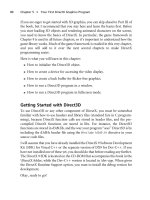
Gateways typically are situated on high-speed backbones such as
FDDI networks, where they connect a mainframe or miniframe to
LANs that are connected to the FDDI backbone via routers (see
Figure 4.4). Although gateways are certainly necessary to connect
networks where data conversion is necessary, they can slow traffic on
the network (especially the data traffic moved between the two con-
nected networks). And because gateways typically connect very dif-
ferent systems, their configuration can be relatively more complex
than other internetworking devices (relatively is the key word; don’t
ever try to tell someone who configures routers that setting up a
gateway is a more difficult task).
PART I Networking Overview
CHAPTER 4 In ternetworking Basics
The horror of broadcast
storms
Because bridges forward
broadcast packets, which
can really flood a network
with data, bridges don’t
protect you against broad-
cast storms.
Malfunctioning NICs and
other devices can generate
a large amount of broad-
cast packets, resulting in a
broadcast storm that can
cripple an entire network.
Email gateways
Another common use of
gateways is as translators
between different email
standards. For example, a
gateway is used to trans-
late between Lotus Notes
Mail server and a
Microsoft Exchange Server
(an email server).
7 5
PART I
Bu ilding a Campus Network CHAPTER 4
Building a Campus Network
Before leaving the subject of internetworking, a few words should be
said about network scale. A Campus network is defined as a portion
of the enterprise network that serves an entire corporation or institu-
tion. Network campuses usually are limited to a building or group of
buildings and primarily use LAN technologies, such as Ethernet,
Token Ring, and FDDI.
Building and maintaining a campus-sized network is really a study in
connecting different LAN architectures (using routers) and taking
advantage of internetworking devices that help relieve congestion on
the network (such as switches and bridges).
Networking the enterprise—connecting the various campus net-
works—requires the use of WAN technologies, which also employ
internetworking devices, particularly routers with the appropriate
WAN interfaces.
The next chapter discusses how a router works. This should help you
take the puzzle pieces that were provided to you in Chapters 1, 3,
and 4 and allow you to better understand how LANs can become
WANs and how networking the enterprise isn’t an insurmountable
task (at least in theory).
FIGURE 4.4
Gateways provide the
connecting point
between high-speed
backbones and main-
frame and miniframe
computers.
I thought routers were
gateways
When you configure a
particular computer on a
network (particularly on a
TCP/IP network), you must
configure the default
gateway for the node. The
default gateway is typically
the logical address of the
router port that the node
(and the rest of its subnet)
connects to. Don’t confuse
routerinterfaces (when
they are referred to as
gateways) with actual
gateways that translate
data between two different
computer systems.
How a Router Wo r k s
Routing Basics
•
Routable Protocols
•
Routing Protocols
•
Routing Protocol Basics
•
Types of Routing Protocols
•
5
c h a p t e r
7 8
Routing Basics
In cases where information needs to be moved between two net-
works, an internetworking device, called a router (you learned a little
bit about routers in Chapter 4, “Internetworking Basics”), is respon-
sible for the movement of this data. Routing data on an internetwork
requires that a couple of different events take place: an appropriate
path for the packets must be determined, and then the packets must
be moved toward their final destination.
Both path determination and routing of packets (or switching as it is
also referred to—packets are switched from an incoming interface to
an outgoing interface on the router) take place at layer 3 (Network
layer) of the OSI model. Another important layer 3 event is the reso-
lution of logical addresses (such as IP numbers when TCP/IP is the
routed protocol) to actual hardware addresses. Additional discussion
related to these three layer 3 events will give you a better idea of the
overall routing process.
SEE ALSO
➤ To review the OSI model before continuing with this chapter, see page 35.
Path Determination
As discussed in Chapter 4, routers enable you to divide a large net-
work into logical subnets; doing so keeps network traffic local on
each subnet, enabling you to take better advantage of the bandwidth
available. It’s then the job of the router to move data packets between
these subnets when necessary. Routers can also serve as the connec-
tive device between your network (all your subnets are viewed by
other enterprise networks as a single network even though you’ve
divided them into logical parts). Routers also can serve as the con-
nective device to other networks to which your network may be
attached. The best example of many different networks connected
for communication purposes is the Internet.
For the purpose of discussion, let’s create a network that contains
subnets that are connected by a router. You will also create a logical
addressing system.
PART I Networking Overview
CHAPTER 5 Ho w a Rout er Wo r k s
Understanding subnets
Creating subnets is an
extremely important part of
implementing routing on a
network. For now, under-
stand that subnets are logi-
cal divisions of a larger
corporate network.
Creating subnets in a
TCP/IP environment will be
discussed in great detail in
Chapter 10, “TCP/IP
Primer.”
7 9
PART I
Rout ing Basics CHAPTER 5
Figure 5.1 shows a network that has been divided into two subnets
using a router. The type of connections between the subnets
(Ethernet, Token Ring, and so on) and the router aren’t important
at this point in our discussion, so just suppose that the appropriate
protocols and interface connections would be used to connect these
subnets to the router.
Don’t try this at home
Be advised that the logical
addresses that you assign
to your nodes and router
interfaces are for our dis-
cussion of how the router
determines when and when
not to forward frames to a
network. These aren’t real
logical addresses. Real log-
ical addresses such as IP
addresses would be used
on a real-world network.
FIGURE 5.1
A network divided into
two logical subnets.
In this example, the router has two network interfaces, Interface 1
and Interface 2, which are connected to Subnet 1 and Subnet 2,
respectively. The logical addressing system that is used to address the
various nodes on the network (logical addresses must be assigned to
each interface on the router as well) is the subnet number followed
by a letter designation. So, Node A on Subnet 1 is assigned the logi-
cal address 1A (subnet designation then node designation).
8 0
Each node on the network will also have a hardware address
(remember that a hardware address is actually assigned to each NIC
when they are built at the factory; router interfaces are also assigned
a burned-in hardware address when they are manufactured). For ease
of discussion, the hardware addresses for each of the nodes is an X
followed by a number. For example, the hardware address for Node
A on Subnet 2 is X4 (remember all hardware addresses are different,
that’s how the cards are manufactured).
Now that you have a small internetwork, let’s take a look at what
happens when one of the computers attempts to send packets to
another computer on the network.
Logical and Hardware Addresses
When you connect networks using a router, you end up with two
different types of data traffic. You end up with local data traffic,
where nodes on the same subnet communicate with each other. You
also have network traffic where nodes on different subnets are com-
municating with each other. This type of traffic must pass through
the router. The next two sections explain how communication within
a subnet and communication between subnets take place.
Communication on the Same Subnet
First, let’s look at a situation in which two computers on the same
subnet communicate. Node A on Subnet 1 must send data to Node
B on Subnet 1. Node A knows that the packets must go to the logical
address 1B and Node A knows that 1B resides on the same subnet
(so in this case the router will not actively be involved in the move-
ment of packets). However, the logical address 1B must be resolved
to an actual hardware address.
Now, Node A might already know that logical address 1B actually
refers to the hardware address X2. Computers actually maintain
small memory caches where they keep this type of logical-to-hard-
ware address-resolution information. If Node A has no idea what the
hardware address of logical address 1B is, it will send a message out
to the network asking for the logical address 1B to be resolved to a
hardware address. When it receives the information, it will send the
packets to Node B, which accepts the packets because they are
tagged with its hardware address—X2.
PART I Networking Overview
CHAPTER 5 Ho w a Rout er Wo r k s
Real-world addresses
To give you an idea of what
the addresses for these
various router interfaces
and nodes would be in a
real IP network, each node
and interface is listed
below with a Class B IP
address:
Subnet 1:130.10.16.0
Node A: 130.10.16.2
Node B: 130.10.16.3
Router Interface 1:
130.10.16.1
Subnet 2: 130.10.32.0
Node A: 130.10.32.2
Router Interface 2:
130.10.32.1
Notice that subnetting has
taken place on the network
and the Subnet 1 nodes
and router interface have
the third octet value of 16
and the Subnet 2 nodes
and router interface have a
third octet value of 32;
these different numbers
identify the different sub-
nets used. You will learn all
about this in Chapter 10,
“TCP/IP Primer.”
8 1
PART I
Rout ing Basics CHAPTER 5
As you can see, node-to-node communication on the same subnet is
pretty straightforward.
Communication Between Different Subnets
Now let’s look at a scenario where a computer wants to send data to
a computer on another subnet.
Node A on Subnet 1 wants to send data to Node A on Subnet 2. So,
Node A on Subnet 1 wants to send the data to logical address 2A.
Node A on Subnet 1 knows that address 2A isn’t on the local subnet,
so it will send the packets to its default gateway, which is the router
interface that is connected to Subnet 1. In this case the logical
address of the Node A (on Subnet 1) gateway is 1C. However, again
this logical address must be resolved to a hardware address—the
actual hardware address of Router Interface 1.
Again, using broadcast messages, Node 1 on Subnet 1 receives the
hardware address information related to logical address 1C (the
hardware address is X3) and sends the packets on to Router 1 via
Router Interface 1. Now that the router has the packets, it must
determine how to forward the packets so that they end up at the des-
tination node. It will take a look at its routing table and then switch
the packets to the interface that is connected to the destination sub-
net.
Packet Switching
After the router has the packets, packet switching comes into play.
This means that the router will move the packets from the router
interface that they came in on and switch them over to the router
interface connected to the subnet they must go out on. However, in
some cases the packets might have to pass through more than one
router to reach the final destination. In our example, only one router
is involved. Router 1 knows that the logical address 2A is on Subnet
2. So the packets will be switched from Router Interface 1 to Router
Interface 2.
Again, broadcast messages are used to resolve logical address 2A to
the actual hardware address X4. The packets are addressed appropri-
ately and then forwarded by the router to Subnet 2. When Node A
on Subnet 2 sees the packets with the Hardware Address X4, it grabs
the packets.
Nodes collect
addressing information
Computers use broadcast
messagesand tables of
information (that they build
from broadcast information
placed out on the network
by other computers) to
determine which addresses
are local and which
addresses are remote on
an internetwork.
8 2
So, you can see that routing involves both the use of logical address-
ing and hardware addressing to get packets from a sending computer
to a destination computer. Each routable protocol (TCP/IP versus
IPX/SPX) uses a slightly different scheme to resolve logical addresses
to hardware addresses, but the overall theory is pretty much the
same as outlined here (TCP/IP addressing was used as the model for
our discussion).
Routing Tables
Before I finish this basic discussion of routing, we should discuss how
the router determines which router port it switches the packets to
(this information will be reviewed when IP routing is discussed in
Chapter 11, “Configuring IP Routing”). Routers use software to cre-
ate routing tables. These routing tables contain information on
which the hardware interface on the router is the beginning route
(for the router) that will eventually get the packets to the destination
address.
Routers, however, aren’t concerned with individual node addresses
when they build their routing tables; they are only concerned with
getting a particular set of packets to the appropriate network. For
example, using your logical addressing system from Figure 5.1, a
router’s routing table would appear as shown in Table 5.1. Notice
that each router interface is mapped to a particular subnet. That way
the router knows that when it examines the logical address of a
packet, it can determine which subnet to forward the packets to.
Table 5.1 A Basic Routing Table for Router 1
Subnet Logical Designation Router Interface
1 1
2 2
Basically, this routing table means that packets that are destined for
any node on Subnet 1 would be routed to the Router 1 Interface on
the router. Any packets destined for Subnet 2 would be switched to
the Router Interface 2 (just as I discussed earlier). Obviously, the log-
ical designation for a subnet on a real-world network would consist
PART I Networking Overview
CHAPTER 5 Ho w a Rout er Wo r k s
Where do routing tables
come from?
Routing tables actually
have two sources. In static
routing, the network admin-
istrator actually types in
the different routes that
are available between seg-
ments on the internetwork.
These network administra-
tor–created routing tables
use a series of router com-
mands to build a table that
looks somewhat like Figure
5.1. Routing tables can also
be built dynamically by
routing protocols such as
RIP and IGRP (which are
discussed later in this
chapter). Dynamic routing
tables also end up looking
like a table (again some-
what like Figure 5.1).
8 3
PART I
Rout ing Basics CHAPTER 5
of something like a network IP address, such as 129.10.1.0, which
designates a class B IP subnetwork. And the router interface would
be designated by the type of network architecture it supports, such as
E0 for the primary Ethernet interface, or S0 for the primary serial
interface on the router.
When multiple routers are involved—on larger networks—the rout-
ing tables become populated with more information. For example,
let’s expand your one router, two-subnet network into five subnets
that employ two routers. Figure 5.2 shows this network.
FIGURE 5.2
A network dividedinto
five logical subnets that
use two routers.
Now, you might be thinking that you see only four subnets. Actually,
any serial connection between two routers is, in effect, a separate
subnet and must be provided with unique logical addresses.
With the size of the network expanded and the number of subnets
increased, Router 1 will have a decidedly different routing table. It
now must potentially pass on packets that go to nodes on Subnets 4
8 4
and 5. However, as I stated earlier, a router doesn’t worry about get-
ting the packets to the actual recipient nodes; it only forwards the
packets so that they get to the correct subnet.
Table 5.2 shows a routing table for Router 1 using your (fictional)
logical addressing system for your subnets. Notice that Router 1 for-
wards packets for Subnets 4 and 5 through the same interface—its
Interface 3. So, Router 1 is content with forwarding packets for
Subnets 4 and 5 (sent from Subnets 1 or 2) to Router 2. Router 2 is
then responsible for switching the packets to the correct interface
that is connected to the appropriate subnet.
Table 5.2 An Expanded Routing Table for Router 1
Subnet Logical Designation Router Interface
1 1
2 2
4 3
5 3
Router 2 would have a similar routing table that would designate
that all packets for Subnets 1 and 2 be routed out of its Interface 1 to
Router 1. Router 1 would then handle the routing of the packets to
the appropriate subnet.
All these routing decisions made by the routers will involve software.
Software that is responsible for network transport (network, or
routable, protocols such as TCP/IP, IPX/SPX, and AppleTalk) and
software that helps the router determine the best path for a set of
packets to the next step in their journey to a final node destination.
This type of software is called a routing protocol. Routable protocols
(network protocols that can be routed) and routing protocols will be
discussed in the next two sections.
SEE ALSO
➤ For more information on IP routing and routing tables, see page 195.
PART I Networking Overview
CHAPTER 5 Ho w a Rout er Wo r k s
8 5
PART I
Routing Protocols CHAPTER 5
Routable Protocols
Before you take a look at the protocols that determine the path for
packets routed through the router (and also maintain the routing
table used by the router to forward the packets), a few words should
be said about routable or routed protocols. Chapter 2, “The OSI
Model and Network Protocols,” discussed commonly used network
protocols: TCP/IP, IPX/SPX, AppleTalk, and NetBEUI. Of these
four protocols only TCP/IP, IPX/SPX, and AppleTalk are routable.
This is because these three protocols all provide enough information
in the Network layer header of their packets for the data to be sent
from sending node to destination node even when the packets must
be forwarded across different networks (by a device such as a router).
SEE ALSO
➤ To review network protocols such as TCP/IP, see page 44.
Routing Protocols
Whereas routable protocols provide the logical addressing system
that makes routing possible, routing protocols provide the mechanisms
for maintaining router routing tables. Routing protocols allow
routers to communicate, which allows them to share route informa-
tion that is used to build and maintain routing tables.
Several different routing protocols exist, such as Routing
Information Protocol (RIP), Open Shortest Path First (OSPF), and
Enhanced Interior Gateway Protocol (EIGRP). And while these dif-
ferent routing protocols use different methods for determining the
best path for packets routed from one network to another, each basi-
cally serves the same purpose. They help accumulate routing infor-
mation related to a specific routed protocol such as TCP/IP (IP is
the routed portion of the TCP/IP stack).
It’s not uncommon in LANs and WANs to find host and server
machines running more than one network protocol to communicate.
For example, an NT server in a NT Domain (an NT Domain is a
network managed by an NT server called the Primary Domain
Controller) may use TCP/IP to communicate with its member
Why isn’t NetBEUI
routable?
NetBEUI does provide a
logical naming system to
deliver packets to comput-
ers; it uses NetBIOS
names, (the name you give
your computer when you
set it up), which are then
resolved to MAC addresses
on computers using a
series of NetBIOS broad-
casts. Unfortunately, the
NetBIOS naming system
doesn’t have a Network
layer logical addressing
system that can be used to
direct packets across a
router on an internetwork.
NetBIOS names just don’t
provide enough information
(no network information at
all) for the packets to be
moved between the various
networks connected by a
router. Plus the
NetBEUI/NetBIOS network
stack doesn’t contain a
routing protocol. So, in
NetBEUI’s case it has two
strikes and no route.
8 6
clients. But it may also serve as a gateway to various printers and file
servers that use the Novell NetWare operating system; meaning that
the NT server will also embrace IPX/SPX as a network protocol.
These protocols basically operate in their own tracks simultaneously
and do not interfere with each other (see Figure 5.3).
This same concept of simultaneously but independently running
protocols is also embraced by routing protocols. Multiple indepen-
dent routing protocols can run on the same router, building and
updating routing tables for several different routed protocols. This
means that the same network media can actually support different
types of networking.
PART I Networking Overview
CHAPTER 5 Ho w a Rout er Wo r k s
FIGURE 5.3
Networks can embrace
multiple network proto-
cols, and routers can
simultaneously route
multiple network proto-
cols using multiple rout-
ing protocols.
SEE ALSO
➤ For a quick look at two theoretical routing tables,see page 82.
➤ For more information on the types of routing protocols and specific routing protocols,see
page 91.
8 7
PART I
Routing Protocol Basics CHAPTER 5
Routing Protocol Basics
Routing protocols must not only provide information for router
routing tables (and be able to adequately update routers when rout-
ing paths change), they are also responsible for determining the best
route through an internetwork for data packets as they move from
the sending computer to the destination computer. Routing proto-
cols are designed to optimize routes on an internetwork and also to
be stable and flexible.
Routing protocols are also designed to use little processing overhead
as they determine and provide route information. This means that
the router itself doesn’t have to be a mega computer with several
processors to handle the routing of packets. The next section dis-
cusses the mechanism that routing protocols use to determine paths.
Routing Algorithms
An algorithm is a mathematical process that is used to arrive at a par-
ticular solution. In terms of routing protocols, you can think of the
algorithm as the set of rules or process that the routing protocol uses
to determine the desirability of paths on the internetwork for the
movement of packets. The routing algorithm is used to build the
routing table used by the router as it forwards packets.
Routing algorithms come in two basic flavors: static and dynamic
algorithms. Static algorithms aren’t really a process at all, but consist
of internetwork mapping information that a network administrator
enters into the router’s routing table. This table would dictate how
packets are moved from one point to another on the network. All
routes on the network would be static—meaning unchanging.
The problem with static algorithms (other than it’s a real pain to
have to manually enter this information on several routers) is that
the router cannot adapt to changes in the network topology. If a par-
ticular route becomes disabled or a portion of the internetwork goes
down, there is no way for the routers on the network to adapt to
these changes and update their routing tables so that data packets
continue to move toward their final destinations.
Routed protocols and
routing protocols are
configured on the router
Although this chapter
delves into the theoretical
aspects of how a router
works and discusses the
relationship between
routed and routing proto-
cols, keep in mind that
these are all issues that
you deal with on the router
when you actually config-
ure it. The Cisco IOS pro-
vides the commands and
functions that enable you
to set the routed and rout-
ing protocols used by a
specific router. More on the
Cisco IOS is discussed in
Chapter 9, “Working with
the Cisco IOS.”
8 8
Dynamic algorithms are built and maintained by routing update
messages. Messages that provide information on changes in the net-
work prompt the routing software to recalculate its algorithm and
update the router’s routing table appropriately.
Routing algorithms (and the routing protocols that employ a certain
algorithm) can also be further classified based on how they provide
update information to the various routers on the internetwork.
Distance-vector routing algorithms send out update messages at a pre-
scribed time (such as every 30 seconds—an example is the Routing
Information Protocol—RIP). Routers using distance-vector algo-
rithms pass their entire routing table to their nearest router neigh-
bors (routers that they are directly connected to). This basically sets
up an update system that reacts to a change in the network like a line
of dominos falling. Each router in turn informs its nearest router
neighbors that a change has occurred in the network.
For example, in Figure 5.4, Router 1 realizes that the connection to
Network A has gone down. In its update message (sent at 30-second
intervals), it sends a revised routing table to Router 2 letting its
neighbor know that the path to Network A is no longer available. At
its next update message, Router 2 sends a revised routing table to
Router 3, letting Router 3 know that Router 2 no longer serves as a
path to Network A. This updating strategy continues until all the
routers on the network know that the Network A line is no longer a
valid path to the computers on that particular part of the entire
internetwork.
The downside of distance-vector routing is that routers are basically
using hearsay information to build their routing tables; they aren’t
privy to an actual view of a particular router’s interface connections.
They must rely on information from a particular router as to the sta-
tus of its connections.
Another strategy for updating routing tables on an internetwork is
the link-state routing algorithm. Link-state routing protocols not
only identify their nearest neighbor routers, but they also exchange
link-state packets that inform all the routers on the internetwork
about the status of their various interfaces. This means that only
information on a router’s direct connections is sent, not the entire
routing table as in distance-vector routing.
PART I Networking Overview
CHAPTER 5 How a Rout er Wo r k s
Convergence is the key
for dynamic routing pro-
tocols
When an internetwork
experiences a downed link
or some other network
problem, it’s very important
for all the routers on the
network to update their
routing tables accordingly.
Convergence is the time it
takes for all the routers on
the network to be up-to-
date in terms of the
changes that have taken
place in the network topol-
ogy (such as the unavail-
ability of a certain route
because of a downed line).
The longer it takes for all
the routers on the internet-
work to converge, the
greater the possibility that
packets will be routed to
routes that are no longer
available on the network.
This type of problem is cer-
tainly not unheard of on the
Internet either, and this is
why email can end up trav-
eling a road to nowhere
and never get toits desti-
nation.
8 9
PART I
Routing Protocol Basics CHAPTER 5
This also means that link-state routers are able to build a more com-
prehensive picture of the entire internetwork and make more intelli-
gent decisions when choosing paths for the routing of packets.
Convergence also takes place more rapidly on a link-state routing
system then it does when distance-vector routing is used.
Routing Metrics
Now that you have learned the different types of routing algorithms
(static versus dynamic) and the two ways that they update their
router tables (distance vector versus link state), you should take a
look at how routing protocols actually determine the best route
between a sending computer and a destination computer when more
than one route is available.
Static versus dynamic
routing
Although you might get the
impression that dynamic
routingis a much better
way to manage the
demands of internetwork-
ing (when compared to sta-
tic routing), dynamic
routing does require more
overhead (in terms of band-
width and processing
power) from internetwork-
ing devices such as routers
because of all the broad -
cast messages and editing
of the routing tables.
Dynamic routing is, obvi-
ously, a much more “fun”
process to monitor.
However, in some cases,
setting up static routing
tables can provide an over-
all faster throughput on the
network as packets are
routed.
FIGURE 5.4
In distance-vector rout-
ing, nearest neighbors
provide updated routing
tables.
9 0
Routing algorithms use a metric to determine the suitability of one
path over another. The metric can be several different things such as
the path length, the actual cost of sending the packets over a certain
route, or the reliability of a particular route between the sending and
receiving computers.
For example, RIP, a distance vector routing protocol, uses hop count
as its metric. A hop is the movement of the packets from one router
to another router. If two paths are available to get the packets from
one location to another, RIP will choose the most desirable path
based on the smallest number of hop counts. Figure 5.5 shows an
internetwork where two paths are possible for the routing of packets
between the sending and receiving computers. Because Route A
requires only one hop, it is considered the optimum route for the
packets.
PART I Networking Overview
CHAPTER 5 Ho w a Rout er Wo r k s
Routing updates are sent
to all nearest neighbors
Although Figure 5.4 is con-
cerned with updates
related to the problem with
the connection to Network
A, remember that the
routers send updates to all
their nearest neighbors. So,
while Router 1 is updating
Router 2, Router 2 also
sends an update to Router
1 as well as Router 3 when
it sends its updated routing
table.
FIGURE 5.5
Routing algorithms use a
metric, such as hop
count, to determine the
optimum path for data
packets.
Hybrid routing protocols
Some routing protocols,
such as OSPF, are consid-
ered hybridsbecause they
use distance-vector and
link-state information to
update routing tables.
9 1
PART I
Typ es of Routing Protocols CHAPTER 5
The problem with routing protocols that use only one metric (such
as hop count) is that they become very single minded in their pursuit
of the best route for a particular set of packets. RIP, for example,
doesn’t take the speed or reliability of the lines into account when it
chooses the best path, just the number of hops. So, as shown in
Figure 5.5, even though Route A is the best path according to the
number of hops (and RIP), you are forced to route your packets over
a slower line (the 56-kilobit leased line). This line is not only slow, it
also costs you money. Route B is actually over wire that the company
owns (part of the network infrastructure) and is actually a faster
medium (fast Ethernet at 100Mbps). However, when you use a
routing protocol that uses hop count as the metric it will choose
Route A.
To overcome the lack of flexibility provided by hop count as a met-
ric, several other routing protocols that use more sophisticated met-
rics are available. For example, the Interior Gateway Routing
Protocol (IGRP) is another distance-vector routing protocol that can
actually use 1 to 255 metrics depending on the number set by the
network administrator. These metrics can include bandwidth (the
capacity of the lines involved), load (the amount of traffic already
being handled by a particular router in the path), and communica-
tion cost (packets are sent along the least expensive route). When
several routing metrics are used together to choose the path for
packets, a much more sophisticated determination is made. For
example, in the case of Figure 5.5 a routing protocol that uses met-
rics other than hop counts (such as communication cost) would
choose the route with more hops but less cost to move the packets to
their destination.
Types of Routing Protocols
Real-world internetworks (particularly those for an entire enterprise)
will consist of several routers that provide the mechanism for moving
packets between the various subnets found on the network. To move
packets efficiently it’s not uncommon to divide several connected
routers into subsets of the internetwork. A subset containing several
member routers is referred to as an area. When several areas are
grouped into a higher-level subset, this organizational level is called a
routing domain.
9 2
Figure 5.6 shows an internetwork divided into areas. Each area is
terminated by a high-end router called a border router (or core
router as mentioned in the sidebar). The two border routers are con-
nected to each other, which, in effect, connects the two routing
domains (or autonomous systems on an IP internetwork).
PART I Networking Overview
CHAPTER 5 Ho w a Rout er Wo r k s
IP internetworks can be
divided into routing
domains
In cases where link-state
routing protocols are used
that require greater mem-
ory and processing capabil-
ities from the routers on
the network, it’s not
uncommon to divide the
internetwork into routing
domains. In IP networks, a
routing domain is referred
to as an autonomous sys-
tem. Routing domains (or if
you prefer, autonomous
systems) are typically con-
nected by a higher-end
router called a border
router or core router.
FIGURE 5.6
Internetworks can be
divided into areas that
are connected by area
border routers.
The fact that internetworks can be divided into logical groupings
such as routing domains (or autonomous systems) gives rise to two
different kinds of routing protocols: routing protocols that provide
the routing of packets between routers in a routing domain and rout-
ing protocols that provide the routing of packets between routing
domains.
Interior Gateway Protocols (IGPs) provide the routing of packets within
the routing domain. IGPs such as RIP or IGRP would be configured
on each of the routers in the router domain.
9 3
PART I
Typ es of Routing Protocols CHAPTER 5
Protocols that move data between the routing domains are called
Exterior Gateway Protocols (EGPs). Examples of EGPs are Border
Gateway Protocol (BGP) and Exterior Gateway Protocol (EGP).
Interior Gateway Protocols
The Interior Gateway Protocols consist of distance-vector and link-
state routing protocols. Several different IGPs are available and vary
on the number of metrics used to determine optimum routing paths.
The oldest IGP is the Routing Information Protocol and is discussed
in the following section, along with some of the other commonly
used IGPs.
Routing Information Protocol
Routing Information Protocol (RIP) is a distance-vector, IP-routing pro-
tocol that uses hop count as its metric. And although it is the oldest
IGP, RIP is still in use.
RIP sends out a routing update message every 30 seconds (by Cisco
default), which consists of the router’s entire routing table. RIP uses
the User Datagram Protocol—UDP—(part of the TCP/IP stack) as
the encapsulation method for the sending of routing advertisements.
RIP is limited, however, in that the maximum number of hops that it
will allow for the routing of specific packets is 15. This means that
RIP is fine for smaller, homogenous internetworks, but doesn’t pro-
vide the metric flexibility needed on larger networks.
SEE ALSO
➤ For information on configuring RIP on a Cisco router, see page 202.
Interior Gateway Routing Protocol
The Interior Gateway Routing Protocol (IGRP) was developed by Cisco
in the 1980s. IGRP is a distance-vector routing protocol.
IGRP uses a composite metric that takes into account several vari-
ables; it also overcomes certain limitations of RIP, such as the hop
count metric and the inability of RIP to route packets on networks
that require more than 15 hops.
A real-world example
If you have a small or
medium-sized company
that has an internetwork,
your entire network could
be considered a routing
domain. It would use
Interior Gateway Protocols
such as RIP or IGRP to
move packets between the
subnets or areas in the
domain. Your connection to
the Internet (the global
internetwork) would be
managed by an Exterior
Gateway Protocol such as
Border Gateway Protocol.
More about these individ-
ual routing protocols is pro-
vided in the remainder of
the chapter.
Implementing RIP
RIP is an IP network routing
protocol. The logical divi-
sion of IP networks is the
subnet. Proper subnetting
and a consistent use of IP
subnet masks is crucial
when using RIP on your
routers. Subnetting and IP
subnetmasks will be dis-
cussed in Chapter 11.
9 4
IGRP (when compared to RIP) also employs a longer time period
between routing updates and uses a more efficient format for the
update packets that are passed between routers. IGRP also supports
the use of autonomous systems (similar to the areas discussed earlier in
the chapter), so routers running IGRP can be sequestered into
domains where the router traffic in a particular domain remains
local. This cuts down on the amount of router broadcast communi-
cations using up valuable bandwidth throughout the entire internet-
work.
IGRP’s metric consists of a composite that takes into consideration
bandwidth, delay, load, and reliability when determining the best
route for data moving from a sending node to a particular destina-
tion node. The following list describes how each of these network
parameters is viewed by IGRP when the routing algorithm is used to
build or update a router’s routing table:
■ Bandwidth is the capacity of a particular interface in kilobits. A
serial interface may have a bandwidth of 100,000 kilobits (this
would be a serial interface connected to an ATM switch, which
typically supplies this amount of bandwidth). Unfortunately, the
bandwidth of a particular interface isn’t measured dynamically
(measuring the actual bandwidth available at a particular time)
but set statically by the network administrator using the band-
width command. More about setting serial interfaces will be dis-
cussed in Chapter 15, “Configuring WAN Protocols.”
■ Delay is the amount of time it takes to move a packet from the
interface to the intended destination. Delay is measured in
microseconds and is a static figure set by the network adminis-
trator using the delay command. Several delays have been com-
puted for common interfaces such as Fast Ethernet and IBM
Token Ring. For example, the delay for a Fast Ethernet interface
is 100 microseconds.
■ Reliability is the ratio of expected-to-received keepalives on a
particular router interface. (Keepalives are messages sent by net-
work devices to tell other network devices, such as routers, that
the link between them still exists.) Reliability is measured
dynamically and is shown as a fraction when the show interface
command is used on the router. For example, the fraction
255/255 represents a 100% reliable link.
PART I Networking Overview
CHAPTER 5 Ho w a Rout er Wo r k s
IGRP is all Cisco
Because IGRP was
developed by Cisco and
remains a Cisco proprietary
protocol, IGRP will only be
available on Cisco routers.
In comparison, RIP is a uni-
versal routing protocol that
you will find on IP networks
whether they are routed
using Cisco boxes or prod-
ucts from another vendor
such as 3Com.
Enhanced IGRP builds
on IGRP’s capabilities
Cisco nowprovides an
enhanced version of IGRP
called Enhanced IGRP
(EIGRP). Although it uses
the same metrics as IGRP,
EIGRP provides updates at
irregular intervals to reflect
that a particular metric
such as load or the network
topology has changed. And
because router updates
only include routing infor-
mation that has changed,
EIGRP is less of a band-
width hog when compared
toIGRP.