ccna study guide by sybex phần 2 pot
Bạn đang xem bản rút gọn của tài liệu. Xem và tải ngay bản đầy đủ của tài liệu tại đây (5.96 MB, 75 trang )
The Cisco Three-Layer Hierarchical Model 33
for instance, hierarchy dictates that you ask your boss, not your subordinate.
That is the person whose role it is to grant (or deny) your request.
Hierarchy has many of the same benefits in network design that it does in
other areas of life. When used properly, it makes networks more predictable.
It helps us define at which levels of hierarchy we should perform certain
functions. Likewise, you can use tools such as access lists at certain levels in
hierarchical networks and avoid them at others.
Let’s face it, large networks can be extremely complicated, with multiple
protocols, detailed configurations, and diverse technologies. Hierarchy helps
us summarize a complex collection of details into an understandable model.
Then, as specific configurations are needed, the model dictates the appropri-
ate manner to apply them.
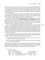
The Cisco hierarchical model can help you design, implement, and main-
tain a scalable, reliable, cost-effective hierarchical internetwork. Cisco defines
three layers of hierarchy, as shown in Figure 1.14, each with specific functions.
FIGURE 1.14 The Cisco hierarchical model
The following are the three layers:
The Core layer
The Distribution layer
The Access layer
Core
layer
Distribution
layer
Access
layer
Copyright ©2000 SYBEX , Inc., Alameda, CA
www.sybex.com
34 Chapter 1
Internetworking
Each layer has specific responsibilities. Remember, however, that the
three layers are logical and are not necessarily physical devices. Consider the
OSI model, another logical hierarchy. The seven layers describe functions
but not necessarily protocols, right? Sometimes a protocol maps to more
than one layer of the OSI model, and sometimes multiple protocols commu-
nicate within a single layer. In the same way, when we build physical imple-
mentations of hierarchical networks, we may have many devices in a single
layer, or we might have a single device performing functions at two layers.
The definition of the layers is logical, not physical.
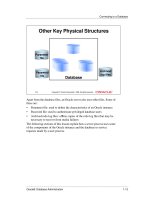
Before you learn about these layers and their functions, consider a com-
mon hierarchical design as shown in Figure 1.15. The phrase “keep local
traffic local” has almost become a cliché in the networking world; however,
the underlying concept has merit. Hierarchical design lends itself perfectly to
fulfilling this concept.
Now, let’s take a closer look at each of the layers.
FIGURE 1.15 Hierarchical network design
Core
layer
Distribution
layer
Access
layer
FDDI Ring
Users’ machines Users’ machines Users’ machines
Workgroups
Copyright ©2000 SYBEX , Inc., Alameda, CA
www.sybex.com
The Cisco Three-Layer Hierarchical Model 35
The Core Layer
The core layer is literally the core of the network. At the top of the hierarchy,
the core layer is responsible for transporting large amounts of traffic both reli-
ably and quickly. The only purpose of the network’s core layer is to switch
traffic as fast as possible. The traffic transported across the core is common to
a majority of users. However, remember that user data is processed at the dis-
tribution layer, which forwards the requests to the core if needed.
If there is a failure in the core, every single user can be affected. Therefore,
fault tolerance at this layer is an issue. The core is likely to see large volumes
of traffic, so speed and latency are driving concerns here. Given the function of
the core, we can now consider some design specifics. Let’s start with some
things we don’t want to do.
Don’t do anything to slow down traffic. This includes using access
lists, routing between virtual local area networks (VLANs), and
packet filtering.
Don’t support workgroup access here.
Avoid expanding the core when the internetwork grows (i.e., adding
routers). If performance becomes an issue in the core, give preference
to upgrades over expansion.
Now, there are a few things that we want to do as we design the core. They
include the following:
Design the core for high reliability. Consider data-link technologies
that facilitate both speed and redundancy, such as FDDI, Fast Ether-
net (with redundant links), or even ATM.
Design with speed in mind. The core should have very little latency.
Select routing protocols with lower convergence times. Fast and
redundant data-link connectivity is no help if your routing tables
are shot!
The Distribution Layer
The distribution layer is sometimes referred to as the workgroup layer and
is the communication point between the access layer and the core. The pri-
mary function of the distribution layer is to provide routing, filtering, and
WAN access and to determine how packets can access the core, if needed.
Copyright ©2000 SYBEX , Inc., Alameda, CA
www.sybex.com
36 Chapter 1
Internetworking
The distribution layer must determine the fastest way that network service
requests are handled; for example, how a file request is forwarded to a
server. After the distribution layer determines the best path, it forwards the
request to the core layer. The core layer then quickly transports the request
to the correct service.
The distribution layer is the place to implement policies for the network.
Here you can exercise considerable flexibility in defining network operation.
There are several items that generally should be done at the distribution
layer. They include the following:
Implementation of tools such as access lists, of packet filtering, and of
queuing
Implementation of security and network policies, including address
translation and firewalls
Redistribution between routing protocols, including static routing
Routing between VLANs and other workgroup support functions
Definitions of broadcast and multicast domains
Things to avoid at the distribution layer are limited to those functions that
exclusively belong to one of the other layers.
The Access Layer
The access layer controls user and workgroup access to internetwork
resources. The access layer is sometimes referred to as the desktop layer. The
network resources most users need will be available locally. The distribution
layer handles any traffic for remote services. The following are some of the
functions to be included at the access layer:
Continued (from distribution layer) access control and policies
Creation of separate collision domains (segmentation)
Workgroup connectivity into the distribution layer
Technologies such as DDR and Ethernet switching are frequently seen in
the access layer. Static routing (instead of dynamic routing protocols) is seen
here as well.
As already noted, three separate levels does not imply three separate routers.
It could be fewer, or it could be more. Remember, this is a layered approach.
Copyright ©2000 SYBEX , Inc., Alameda, CA
www.sybex.com
Assembling and Cabling Cisco Devices 37
Assembling and Cabling Cisco Devices
In this section, I’ll address the corporate environment and the different
types of cabling required to connect an internetwork. To understand
the types of cabling used to assemble and cable Cisco devices, you need to
understand the LAN Physical layer implementation of Ethernet.
Ethernet is a media access method that is specified at the Data Link layer
and uses specific Physical layer cabling and signaling techniques. It is impor-
tant to be able to differentiate between the types of connectors that can be
used to connect an Ethernet network together. I’ll discuss the different
unshielded twisted-pair cabling used today in an Ethernet LAN.
Cabling the Ethernet Local Area Network
Ethernet was first implemented by a group called DIX (Digital, Intel, and
Xerox). They created and implemented the first Ethernet LAN specification,
which the IEEE used to create the IEEE 802.3 committee. This was a
10Mbps network that ran on coax, twisted-pair, and fiber physical media.
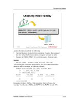
The IEEE extended the 802.3 committee to two new committees known
as 802.3u (FastEthernet) and 802.3q (Gigabit Ethernet). These are both
specified on twisted-pair and fiber physical media. Figure 1.16 shows the
IEEE 802.3 and original Ethernet Physical layer specifications.
FIGURE 1.16 Ethernet Physical layer specifications
When designing your LAN, it is important to understand the different
types of Ethernet media available. It would certainly be great to run Gigabit
Ethernet to each desktop and 10Gbps between switches, and although this
might happen one day, it is unrealistic to think you can justify the cost of that
network today. By mixing and matching the different types of Ethernet
Data Link
(MAC layer)
Physical
Ethernet
802.3
10Base2
10Base5
10BaseT
10BaseF
100BaseTX
100BaseFX
100BaseT4
Copyright ©2000 SYBEX , Inc., Alameda, CA
www.sybex.com
38 Chapter 1
Internetworking
media methods today, you can create a cost-effective network that works
great.
The following bullet points provide a general understanding of where you
can use the different Ethernet media in your hierarchical network:
Use 10Mbps switches at the access layer to provide good performance
at a low price. 100Mbps links can be used for high-bandwidth–
consuming clients or servers. No servers should be at 10Mbps if
possible.
Use FastEthernet between access layer and distribution layer switches.
10Mbps links would create a bottleneck.
Use FastEthernet (or Gigabit if applicable) between distribution layer
switches and the core. Also, you should be implementing the fastest
media you can afford between the core switches. Dual links between
distribution and core switches are recommended for redundancy and
load balancing.
Ethernet Media and Connector Requirements
It’s important to understand the difference between the media access speeds
Ethernet provides. However, it’s also important to understand the connector
requirements for each implementation before making any decision.
The EIA/TIA (Electronic Industries Association and the newer Telecom-
munications Industry Association) is the standards body that creates the
Physical layer specifications for Ethernet. The EIA/TIA specifies that Ether-
net use a registered jack (RJ) connector with a 4 5 wiring sequence on
unshielded twisted-pair (UTP) cabling (RJ-45). The following bullet points
outline the different Ethernet media requirements:
10Base2 50-ohm coax, called thinnet. Up to 185 meters and 30 hosts
per segment. Uses a physical and logical bus with AUI connectors.
10Base5 50-ohm coax called thicknet. Up to 500 meters and 208 users
per segment. Uses a physical and logical bus with AUI connectors. Up to
2500 meters with repeaters and 1024 users for all segments.
10BaseT EIA/TIA category 3, 4, or 5, using two-pair unshielded
twisted-pair (UTP) wiring. One user per segment; up to 100 meters long.
Uses an RJ-45 connector with a physical star topology and a logical bus.
Copyright ©2000 SYBEX , Inc., Alameda, CA
www.sybex.com
Assembling and Cabling Cisco Devices 39
100BaseTX EIA/TIA category 5, 6, or 7 UTP two-pair wiring. One user
per segment; up to 100 meters long. Uses an RJ-45 MII connector with a
physical star topology and a logical bus.
100BaseFX Uses fiber cabling 62.5/125-micron multimode fiber. Point-
to-point topology; up to 400 meters long. Uses an ST or SC connector,
which are duplex media-interface connectors.
1000BaseCX Copper shielded twisted-pair that can only run up to
25 meters.
1000BaseT Category 5, four-pair UTP wiring up to 100 meters long.
1000BaseSX MMF using 62.5 and 50-micron core; uses a 780-nanometer
laser and can go up to 260 meters.
1000BaseLX Single-mode fiber that uses a 9-micron core, 1300-nanometer
laser and can go from 3 km up to 10 km.
100VG-AnyLAN is a twisted-pair technology that was the first 100Mbps LAN.
However, since it was incompatible with Ethernet signaling techniques (it
used a polling media access method), it was not typically used and is essen-
tially dead.
UTP Connections (RJ-45)
The RJ-45 connector is clear so you can see the eight colored wires that con-
nect to the connector’s pins. These wires are twisted into four pairs. Four
wires (two pairs) carry the voltage and are considered tip. The other four wires
are grounded and are called ring. The RJ-45 connector is crimped onto the
end of the wire, and the pin locations of the connector are numbered from
the left, 8 to 1.
Figure 1.17 shows a UTP cable with an RJ-45 connector attached.
The UTP cable has twisted wires inside that eliminate cross talk.
Unshielded cable can be used since digital signal protection comes from the
twists in the wire. The more twists per inch, the farther the digital signal can
supposedly travel without interference. For example, categories 5 and 6 have
many more twists per inch than category 3 UTP does.
Copyright ©2000 SYBEX , Inc., Alameda, CA
www.sybex.com
40 Chapter 1
Internetworking
FIGURE 1.17 UTP wire with an RJ-45 connector attached
Different types of wiring are used when building internetworks. You will
need to use either a straight-through or crossover cable.
Straight-Through
In a UTP implementation of a straight-through cable, the wires on both cable
ends are in the same order. Figure 1.18 shows the pinouts of the straight-
through cable.
FIGURE 1.18 UTP straight-through pinouts
RJ-45 connector
Pin
1
2
3
4
5
6
7
8
Wire Pair
(T Is Tip;
R Is Ring)
Pair 2 T2
Pair 2 R2
Pair 3 T3
Pair 1 R1
Pair 1 T1
Pair 3 R3
Pair 4 T4
Pair 4 R4
1
8
Pin
1
2
3
4
5
6
7
8
Label
RD+
RD–
TD+
NC
NC
TD–
NC
NC
Pin
1
2
3
4
5
6
7
8
Label
TD+
TD–
RD+
NC
NC
RD–
NC
NC
Hub/Switch Server/Router
Copyright ©2000 SYBEX , Inc., Alameda, CA
www.sybex.com
Assembling and Cabling Cisco Devices 41
You can determine that the wiring is a straight-through cable by holding
both ends of the UTP cable side by side and seeing that the order of the wires
on both ends is identical.
You can use a straight-through cable for the following tasks:
Connecting a router to a hub or switch
Connecting a server to a hub or switch
Connecting workstations to a hub or switch
Crossover
In the implementation of a crossover, the wires on each end of the cable are
crossed. Transmit to Receive and Receive to Transmit on each side, for both
tip and ring. Figure 1.19 shows the UTP crossover implementation.
FIGURE 1.19 UTP crossover implementation
Notice that pin 1 on one side connects to pin 3 on the other side, and
pin 2 connects to pin 6 on the opposite end.
You can use a crossover cable for the following tasks:
Connecting uplinks between switches
Connecting hubs to switches
Connecting a hub to another hub
Pin
1
2
3
4
5
6
7
8
Label
RD+
RD–
TD+
NC
NC
TD–
NC
NC
Pin
1
2
3
4
5
6
7
8
Label
RD+
RD–
TD+
NC
NC
TD–
NC
NC
Hub/Switch Hub/Switch
Copyright ©2000 SYBEX , Inc., Alameda, CA
www.sybex.com
42 Chapter 1
Internetworking
Connecting a router interface to another router interface
Connecting two PCs together without a hub or switch
When trying to determine the type of cable needed for a port, look at the port
and see if it is marked with an “X.” Use a straight-through cable when only
one port is designated with an “X.” Use a crossover when both ports are des-
ignated with an “X” or when neither port has an “X.”
Cabling the Wide Area Network
To connect your wide area network (WAN), you need to understand the
WAN Physical layer implementation provided by Cisco as well as the differ-
ent WAN serial connectors. In this section, I will give you that information,
along with the cabling requirements for ISDN BRI connections.
Cisco serial connections support almost any type of WAN service. The
typical WAN connections are dedicated leased lines using High-Level Data
Link Control (HDLC), Point-to-Point Protocol (PPP), Integrated Services
Digital Network (ISDN), and Frame Relay. Typical speeds are anywhere
from 2400bps to 1.544Mbps (T1).
All of these WAN types are discussed in detail in Chapter 10.
HDLC, PPP, and Frame Relay can use the same Physical layer specifica-
tions, but ISDN has different pinouts and specifications at the Physical layer.
Serial Transmission
WAN serial connectors use serial transmission, which is one bit at a time,
over a single channel. Parallel transmission can pass at least 8 bits at a time.
All WANs use serial transmission.
Cisco routers use a proprietary 60-pin serial connector, which you must
buy from Cisco or a provider of Cisco equipment. The type of connector
you have on the other end of the cable depends on your service provider
or end-device requirements. The different ends available are EIA/TIA-232,
EIA/TIA-449, V.35 (used to connect to a CSU/DSU), X.21 (used in X.25),
and EIA-530.
Copyright ©2000 SYBEX , Inc., Alameda, CA
www.sybex.com
Assembling and Cabling Cisco Devices 43
Serial links are described in frequency or cycles-per-second (hertz). The
amount of data that can be carried within these frequencies is called band-
width. Bandwidth is the amount of data in bits-per-second that the serial
channel can carry.
Data Terminal Equipment and Data
Communication Equipment
Router interfaces are, by default, Data Terminal Equipment (DTE) and con-
nect into Data Communication Equipment (DCE), for example, a Channel
Service Unit/Data Service Unit (CSU/DSU). The CSU/DSU then plugs into a
demarcation location (demarc) and is the service provider’s last responsibil-
ity. Typically, the demarc is a jack that has an RJ-45 female connector
located close to your equipment. If you report a problem to your service pro-
vider, they’ll always tell you it tests fine up to the demarc and that the prob-
lem must be the CPE, or Customer Premise Equipment, which is your
responsibility.
The idea behind a WAN is to be able to connect two DTE networks
together through a DCE network. The DCE network includes the CSU/DSU,
through the provider’s wiring and switches, all the way to the CSU/DSU
at the other end. The network’s DCE device provides clocking to the DTE-
connected interface (the router’s serial interface).
Fixed and Modular Interfaces
Some routers Cisco sells have fixed interfaces, while others are modular. The
fixed routers, such as the 2500 series, have set interfaces that can’t be
changed. The 2501 router has two serial connections and one 10BaseT AUI
interface. If you need to add a third serial interface, then you need to buy a
new router—ouch! However, the 1600, 1700, 2600, 3600, and higher rout-
ers have modular interfaces that allow you to buy what you need now and
add almost any type of interface you may need later. The 1600 and 1700 are
limited and have both fixed and modular ports, but the 2600 and up provide
many serials, FastEthernet, and even voice-module availability.
Integrated Services Digital Network (ISDN) Connections
Integrated Services Digital Network (ISDN) Basic Rate Interface (BRI) is
two B (Bearer) channels of 64k each and one D (Data) channel of 16k for sig-
naling and clocking.
Copyright ©2000 SYBEX , Inc., Alameda, CA
www.sybex.com
44 Chapter 1
Internetworking
ISDN BRI routers come with either a U interface or what is known as an
S/T interface. The difference between the two is that the U interface is
already a two-wire ISDN convention that can plug right into the ISDN local
loop. The S/T interface is a four-wire interface and needs a Network Termi-
nation type 1 (NT 1) to convert from a four-wire to the two-wire ISDN
specification.
ISDN is covered in depth in Chapter 10.
The U interface has a built-in NT 1 device. If your service provider uses an
NT 1 device, then you need to buy a router that has an S/T interface. Most
Cisco router BRI interfaces are marked with a U or an S/T. When in doubt,
ask Cisco or the salesperson you bought it from.
Primary Rate Interface (PRI) provides T1 speeds (1.544Mbps) in the U.S. and
E1 speeds (2.048) in Europe. PRI is not discussed further in this course.
The ISDN BRI interface uses an RJ-45, category 5, straight-through cable.
It is important to avoid plugging a console cable or other LAN cable into a
BRI interface on a router, because it will probably ruin the interface. Cisco
says it will ruin it, but I have students do it every week and haven’t lost one
yet (I probably shouldn’t have said that…now I will probably lose one
next week).
Console Connections
All Cisco devices are shipped with console cables and connectors, which allow
you to connect to a device and configure, verify, and monitor it. The cable used
to connect between a PC is a rollover cable with RJ-45 connectors.
The pinouts for a rollover cable are as follows:
1–8
2–7
3–6
4–5
5–4
Copyright ©2000 SYBEX , Inc., Alameda, CA
www.sybex.com
Selecting Cisco Products 45
6–3
7–2
8–1
You can see that you just take a straight-through RJ-45 cable, cut the end
off, flip it over, and reattach a new connector.
Typically, you will use the DB9 connector to attach to your PC and use a
com port to communicate via HyperTerminal. Most Cisco devices now sup-
port RJ-45 console connections. However, the Catalyst 5000 series switch
still uses a DB25 connector.
Set up the terminal emulation program to run 9600bps, 8 data bits, no
parity, 1 stop bit, and no flow control. On some routers, you need to verify
that the terminal emulation program is emulating a VT100 dumb-terminal
mode, not an auto-sense mode, or it won’t work.
Most routers also have an aux port, which is an auxiliary port used to
connect a modem. You can then dial this modem and connect the router to
the aux port. This will give you console access to a remote router that might
be down and that you cannot telnet into. The console port and aux port are
considered out-of-band management since you are configuring the router
“out of the network.” Telnet is considered in-band.
Selecting Cisco Products
You can use the Cisco three-layer model to determine what type
of product to buy for your internetwork. By understanding the services
required at each layer and what functions the internetworking devices per-
form, you can then match Cisco products to your business requirements. To
select the correct Cisco products for your network, start by gathering infor-
mation about where devices need to operate in the internetworking hierar-
chy, and then consider issues like ease of installation, port-capacity
requirements, and other features.
If you have remote offices or other WAN needs, you need to first find out
what type of service is available. It won’t do you any good to design a large
Frame Relay network only to discover that Frame Relay is only supported
in half the locations you need. After you research and find out about the
Copyright ©2000 SYBEX , Inc., Alameda, CA
www.sybex.com
46 Chapter 1
Internetworking
different options available through your service provider, you can choose the
Cisco product that fits your business requirements.
You have a few options, typically: dial-up asynchronous connections,
leased lines up to 1.544Mbps, Frame Relay, and ISDN, which are the most
popular WAN technologies. However, xDSL is the new front-runner to take
over as the fastest, most reliable, cheapest WAN technology. You need to
consider your usage before buying and implementing a technology. For
example, if your users at a remote branch are connected to the corporate
office more than three to four hours a day, then you need either Frame Relay
or a leased line. If they connect infrequently, then you might get away with
ISDN or dial-up connectivity.
The next sections discuss the different types of Cisco hubs, routers, and
switches you can use to build a hierarchical network.
Cisco Hubs
It is hard for me to imagine that you would call Cisco and ask to buy a hub,
but I suppose it does happen or they wouldn’t be selling them. Cisco actually
has an extensive listing of hubs that address an amazing variety of selection
issues.
Before you buy any hub, you need to know—not think you know, but
actually know—which users can use a shared 10Mbps or shared 100Mbps
network. The lower-end model of hubs Cisco offers supports only 10Mbps,
while the middle-of-the-road one offers both 10- and 100Mbps auto-sensing
ports. The higher-end hubs offer network-management port and console
connections. If you are going to spend enough to buy a high-end hub, you
should consider just buying a switch. Figure 1.20 shows the different hub
products Cisco offers. Any of these hubs can be stacked together to give you
more port density.
These are the selection issues you need to know:
Business requirements for 10- or 100Mbps
Port density
Management
Ease of operation
Copyright ©2000 SYBEX , Inc., Alameda, CA
www.sybex.com
Selecting Cisco Products 47
FIGURE 1.20 Cisco hub products
Cisco Routers
When you think of Cisco, what do you think of first? Hubs? I don’t think so.
You think of routers, of course. Cisco makes the best routers in the world.
Everyone knows this, and it is also one of the reasons you are even reading
this book.
It seems as though Cisco comes out with a new router almost every
month. It is hard to keep up with their new offerings. A key criterion when
selecting router products is knowing what feature sets you need to meet your
business requirements. For example, do you need IP, Frame Relay, and VPN
support? How about IPX, AppleTalk, and DECnet? Cisco has it all.
The other features you need to think about when considering different
product-selection criteria are port density and interface speeds. As you get
into the higher-end models, you see more ports and faster speeds. For exam-
ple, the new 12000 series model is Cisco’s first gigabit switch and has enor-
mous capability and functionality.
Cisco 1500
Micro Hub
Cisco 1528
Micro Hub 10/100
Cisco
FastHub100
Cisco
FastHub200
Cisco
FastHub300
Cisco
FastHub400
Copyright ©2000 SYBEX , Inc., Alameda, CA
www.sybex.com
48 Chapter 1
Internetworking
You can tell how much a product is going to cost by looking at the model
number. A stripped-down 12000 series switch with no cards or power sup-
plies starts at about $12,000. The price can end up at well over $100,000 for
a loaded system. Seems like a loaded 12000 series system would be great for
my little home network.
You also need to think about WAN support when buying a router. You
can get anything you want in a Cisco router, but you just have to be familiar
with the service provided for your area.
Figure 1.21 shows some of the router products Cisco sells.
FIGURE 1.21 Cisco router products
Cisco
700/800
series
Cisco
1600/1700
series
Cisco
2500
series
Cisco
2600
series
Cisco
3600
series
Cisco
4000
series
Cisco
7000
series
Cisco
12000 GSR
series
AS
5000
series
Home office solutions
Small office solutions
Branch office solutions
Central site solutions
Copyright ©2000 SYBEX , Inc., Alameda, CA
www.sybex.com
Selecting Cisco Products 49
The Cisco 800 series router has mostly replaced the Cisco 700 series
because the 700 series does not run the Cisco IOS. In fact, I hope Cisco will
soon stop selling the 700 series routers altogether. They are difficult to con-
figure and maintain.
The main selections involved in choosing Cisco routers are listed below:
Scale of routing features needed
Port density and variety requirements
Capacity and performance
Common user interface
Cisco Switches
It seems like switch prices are dropping almost daily. I just received an
e-mail from Cisco announcing that the Catalyst 2900 series switches have
dropped in price 30 percent. About four years ago a 12-port 10/100 switch
card for the Catalyst 5000 series switch was about $15,000. Now you can
buy a complete Catalyst 5000 with a 10/100 card and supervisor module
for about $7500 or so. My point is that with switch prices becoming rea-
sonable, it is now easier to install switches in your network. Why buy hubs
when you can use switches? I think every closet should have at least one
switch.
Cisco has a huge assortment of switches to meet absolutely every busi-
ness need. You must consider whether you need 10/100 or 1000Mbps for
each desktop or to connect between switches. ATM (asynchronous trans-
fer mode) is also a consideration; however, with Gigabit Ethernet out and
10Gbps links just around the corner, who needs ATM? The next criteria
to consider are port density. The lower-end models start at 12 ports, and
the higher-end models can provide hundreds of switched ports per
switch.
Figure 1.22 shows the Cisco-switch product line.
Copyright ©2000 SYBEX , Inc., Alameda, CA
www.sybex.com
50 Chapter 1
Internetworking
FIGURE 1.22 Cisco Catalyst switch products
The selection issues you need to know when choosing a Cisco switch are
listed below:
Business requirements for 10,100 or even 1000Mbps
Need for trunking and interswitch links
Workgroup segmentation (VLANs)
Port density needs
Different user interfaces
Desktop/workgroup
solutions
Wiring
closet/backbone
solutions
Cisco 1548 Micro
Switch 10/100
Catalyst
1900/2820 series
Catalyst 2900
series XL
Catalyst 2900
series
Catalyst
3000 series
Catalyst
8500 series
Catalyst
5000 series
Copyright ©2000 SYBEX , Inc., Alameda, CA
www.sybex.com
Summary 51
Summary
This chapter began with a discussion of the OSI model, which is a
seven-layer model used to help application developers design applications
that can run on any type of system or network. I provided complete details
of each layer and discussed how Cisco views the specifications of the model
Different types of devices are specified at each of the OSI model’s layers.
This chapter discussed the different types of devices, cables, and connectors
used at each layer.
Also, I provided an introduction to the Cisco hierarchical network model,
which was created to help administrators design and understand hierarchical
networks. By using the Cisco three-layer model, you can effectively design,
implement, and maintain any size network.
Cisco makes a large range of router, hub, and switch products. I discussed
the different products Cisco creates and sells so that you can make more
informed decisions when building your internetwork.
Key Terms
Before taking the exam, be sure you’re familiar with the following terms.
access layer core layer
Application layer Data Communication Equipment
(DCE)
Application-Specific Integrated
Circuits (ASICs)
data frame
Basic Rate Interface (BRI) Data Link layer
bridges Data Terminal Equipment (DTE)
broadcast domain distribution layer
buffer encapsulation
Carrier Sense Multiple Access with
Collision Detect (CSMA/CD)
Ethernet
Channel Service Unit/Data Service
Unit (CSU/DSU)
flow control
Copyright ©2000 SYBEX , Inc., Alameda, CA
www.sybex.com
52 Chapter 1
Internetworking
frame Protocol Data Units (PDUs)
full duplex registered jack (RJ) connector
half duplex router
hierarchical addressing Session layer
hubs simplex
Integrated Services Digital
Network (ISDN)
state transitions
layered architecture switch
Media Access Control (MAC)
address
thicknet
Network layer thinnet
Organizationally Unique
Identifier (OUI)
Transport layer
OSI (Open Systems
Interconnection) model
unshielded twisted-pair (UTP)
Physical layer wide area network (WAN)
Presentation layer windowing
Copyright ©2000 SYBEX , Inc., Alameda, CA
www.sybex.com
Written Labs 53
Written Labs
In this section, you will complete the following labs:
Lab 1.1: OSI Questions
Lab 1.2: Defining the OSI Layers and Devices
Lab 1.3: Identifying Collision and Broadcast Domains
Lab 1.1: OSI Questions
Answer the following questions about the OSI model:
1. Which layer chooses and determines the availability of communicat-
ing partners, along with the resources necessary to make the connec-
tion; coordinates partnering applications; and forms a consensus on
procedures for controlling data integrity and error recovery?
2. Which layer is responsible for converting data packets from the Data
Link layer into electrical signals?
3. At which layer is routing implemented, enabling connections and path
selection between two end systems?
4. Which layer defines how data is formatted, presented, encoded, and
converted for use on the network?
5. Which layer is responsible for creating, managing, and terminating
sessions between applications?
6. Which layer ensures the trustworthy transmission of data across a
physical link and is primarily concerned with physical addressing, line
discipline, network topology, error notification, ordered delivery of
frames, and flow control?
7. Which layer is used for reliable communication between end nodes
over the network and provides mechanisms for establishing, maintain-
ing, and terminating virtual circuits; transport-fault detection and
recovery; and controlling the flow of information?
Copyright ©2000 SYBEX , Inc., Alameda, CA
www.sybex.com
54 Chapter 1
Internetworking
8. Which layer provides logical addressing that routers will use for path
determination?
9. Which layer specifies voltage, wire speed, and pin-out cables and
moves bits between devices?
10. Which layer combines bits into bytes and bytes into frames, uses MAC
addressing, and provides error detection?
11. Which layer is responsible for keeping different applications’ data sep-
arate on the network?
12. Which layer is represented by frames?
13. Which layer is represented by segments?
14. Which layer is represented by packets?
15. Which layer is represented by bits?
16. Put the following in order of encapsulation:
packets
frames
bits
segments
17. Put the following in order of de-encapsulation:
packets
frames
bits
segments
Copyright ©2000 SYBEX , Inc., Alameda, CA
www.sybex.com
Written Labs 55
Lab 1.2: Defining the OSI Layers and Devices
Fill in the blanks with the appropriate layer of the OSI or hub, switch, or
router device.
Description Device or OSI Layer
Logical port numbers are used at
this layer.
This device sends and receives
information about the Network
layer.
This layer creates a virtual circuit
before transmitting between two
end stations.
This layer uses service access points.
This device uses hardware addresses
to filter a network.
Ethernet is defined at these layers.
This layer supports flow control
and sequencing.
This device can measure the
distance to a remote network.
Logical addressing is used at this
layer.
Hardware addresses are defined at
this layer.
This device creates one big
collision domain and one large
broadcast domain.
This device creates many smaller
collision domains, but the network
is still one large broadcast domain.
This device breaks up collision
domains and broadcast domains.
Copyright ©2000 SYBEX , Inc., Alameda, CA
www.sybex.com
56 Chapter 1
Internetworking
Lab 1.3: Identifying Collision and Broadcast Domains
In Figure 1.23, identify the amount of collision domains and broadcast
domains in each network.
FIGURE 1.23 Identifying the amount of collision and broadcast domains
ABCD
Collision domains:
Broadcast domains:
C
D
AB
Copyright ©2000 SYBEX , Inc., Alameda, CA
www.sybex.com
Review Questions 57
Review Questions
1. Which Cisco layer is responsible for breaking up collision domains?
A. Physical
B. Access
C. Core
D. Network
E. Distribution
F. Data Link
2. PDUs at the Network layer of the OSI are called what?
A. Core
B. Frames
C. Packets
D. Segments
E. Access
F. Distribution
G. Transport
3. At which Cisco layer would broadcast domains be defined?
A. Core
B. Network
C. Physical
D. Distribution
E. Access
F. Transport
Copyright ©2000 SYBEX , Inc., Alameda, CA
www.sybex.com