cwna certified wireless network administrator official study guide phần 8 doc
Bạn đang xem bản rút gọn của tài liệu. Xem và tải ngay bản đầy đủ của tài liệu tại đây (844.72 KB, 38 trang )
239 Chapter 9 –Troubleshooting Wireless LAN Installations
If you do co-locate three access points in this manner, it is recommended that you
implement the co-location using the same manufacturer's hardware for all three access
points. It has been noted in many lab scenarios that using differing vendors' equipment
for co-location has a negative effect on throughput of one or more of the access points.
This negative effect could be simply due to differing output power and proximity
between access points, but could be related to many other factors as well.
Solutions for Co-location Throughput Problems
As a wireless LAN installer or administrator, you really have two choices when
considering access point co-location. You can accept the degraded throughput, or you
can attempt a workaround. Accepting the fact that your users will not have 5 Mbps of
actual throughput to the network backbone on each access point may be an acceptable
scenario. First, however, you must make sure that the users connecting to the network in
this situation can still be productive and that they do not actually require the full 5 Mbps
of throughput. The last thing you want to be responsible for as a wireless LAN
administrator is a network that does not allow the users to do their jobs or achieve the
connections that they require. An administrator's second option in this case is to attempt
a workaround. Below, we describe some of the alternatives to co-location problems.
Use Two Access Points
One option, which is the easiest, is to use channels 1 and 11 with only 2 access points, as
illustrated in Figure 9.11. Using only these two channels will ensure that you have no
overlap between channels regardless of proximity between systems, and therefore, no
detrimental effect on the throughput of each access point. By way of comparison, two
access points operating at the maximum capacity of 5.5 Mbps (about the best that you can
expect by any access point), give you a total capacity of 11 Mbps of aggregate
throughput, whereas three access points operating at approximately 4 Mbps each
(degraded from the maximum due to actual channel overlap) on average yields only 12
Mbps of aggregate throughput. For an additional 1 Mbps of throughput, an administrator
would have to spend the extra money to buy another access point, the time and labor to
install it, and the continued burden of managing it.
FIGURE 9.11 Using two access points instead of three
2.401 GHz 2.473 GHz
Channel 1 Channel 6 Channel 11
f
P
Remove this access point
allowing more channel separation
between access points for greater
throughput
CWNA Study Guide © Copyright 2002 Planet3 Wireless, Inc.
Chapter 9 –Troubleshooting Wireless LAN Installations 240
In certain instances, the extra 1 Mbps of bandwidth might still be advantageous, but in a
small environment, it might not be practical. Don't forget that this scenario applies only
to access points located in the same physical space serving the same client base, but using
different, non-overlapping channels. This configuration does not apply to channel reuse,
where cells on different non-overlapping channels are alternately spread throughout an
area to avoid co-channel interference.
Use 802.11a Equipment
As a second option, you could use 802.11a compliant equipment operating in the 5 GHz
UNII bands. The 5 GHz UNII bands, which are each wider than the 2.4 GHz ISM band,
have three usable bands, and each band allows for four non-overlapping channels. By
using a mixture of 802.11b and 802.11a equipment, more systems can be co-located in
the same space without fear of interference between systems. With two (or three) co-
located 802.11b systems and up to 8 co-located 802.11a systems, there is the potential for
an incredible amount of throughput in the same physical space. The reason that we
specify 8 instead of 12 co-located access points with 802.11a is that only the lower and
middle bands (with 4 non-overlapping channels each) are specified for indoor use.
Therefore, indoors, where most access points are placed, there's normally only the
potential for up to 8 access points using 802.11a compliant devices.
Issues with 802.11a Equipment
802.11a equipment is now available from only a few vendors, and is more expensive than
equipment that uses the 2.4 GHz frequency band. However, the 5 GHz band has the
advantage of many more non-overlapping channels than the 2.4 GHz band (8 vs. 3),
allowing you to implement many more co-located access points.
You must keep in mind that while the 2.4 GHz band allows for less expensive gear, the
2.4 GHz band is much more crowded, which means you are more likely to encounter
interference from other nearby wireless LANs. Remember that 802.11a devices and
802.11b devices are incompatible. These devices do not see, hear, or communicate with
one another because they utilize different frequency bands and different modulation
techniques.
Summary
Why do "non-overlapping" channels overlap? There could be many answers to this
question; however, it seems that the greatest cause is access points being located too
close together. By separating the access points by a greater distance, the overlap between
theoretically non-overlapping channels is reduced. Watching this configuration on a
spectrum analyzer, you can see that for close-quarters co-location, there needs to be a
channel separation larger than 3 MHz; however, since that is what we, as administrators,
have to work with, we have to find a workaround.
We can either physically separate the radios by a further distance or we can use channels
further than 3 MHz apart (hence the suggestion of using channels 1 & 11 only for close-
quarters co-location). It also seems that co-location of different vendors' equipment
makes a difference as well. Using the same vendor's equipment for close-quarters co-
CWNA Study Guide © Copyright 2002 Planet3 Wireless, Inc.
241 Chapter 9 –Troubleshooting Wireless LAN Installations
location has less severe overlapping than does using multiple vendors' equipment.
Whether this phenomenon is due to inaccuracies in the radios, or just due to each
vendor's implementation of hardware around the radio, is unknown.
Idiosyncrasies like non-overlapping channels overlapping one will not be tested on the
CWNA exam. For the exam it is important to know the theory of how co-channel
throughput is theoretically supposed to work.
Types of Interference
Due to the unpredictable behavioral tendencies of RF technology, you must take into
account many kinds of RF interference during implementation and management of a
wireless LAN. Narrowband, all-band, RF signal degradation, and adjacent and co-
channel interference are the most common sources of RF interference that occur during
implementation of a wireless LAN. In this section, we will discuss these types of
interference, how they affect the wireless LAN, how to locate them, and in some cases
how to work around them.
Narrowband
Narrowband RF is basically the opposite of spread spectrum technology. Narrowband
signals, depending on output power, frequency width in the spectrum, and consistency,
can intermittently interrupt or even disrupt the RF signals emitted from a spread spectrum
device such as an access point. However, as its name suggests, narrowband signals do
not disrupt RF signals across the entire RF band. Thus, if the narrowband signal is
primarily disrupting the RF signals in channel 3, then you could, for example, use
Channel 11, where you may not experience any interference at all. It is also likely that
only a small portion of any given channel might be disrupted by narrowband interference.
Typically, only a single carrier frequency (a 1 MHz increment in an 802.11b 22 MHz
channel) would be disrupted due to narrowband interference. Given this type of
interference, spread spectrum technologies will usually work around this problem without
any additional administration or configuration.
FIGURE 9.12 Picture of a handheld digital spectrum analyzer showing a narrowband signal
CWNA Study Guide © Copyright 2002 Planet3 Wireless, Inc.
Chapter 9 –Troubleshooting Wireless LAN Installations 242
To identify narrowband interference, you will need a spectrum analyzer, shown above in
Figure 9.12. Spectrum analyzers are used to locate and measure narrowband RF signals,
among other things. There are even handheld, digital spectrum analyzers available that
cost approximately $3,000. That may seem like quite a bit of money to locate a
narrowband interference source, but if that source is disabling your network, it might be
well worth it.
As an alternative, some wireless LAN vendors have implemented a software spectrum
analyzer into their client driver software. This software uses a FHSS PCMCIA card to
scan the useable portion of the 2.4 GHz ISM band for RF signals. The software
graphically displays all RF signals between 2.400 GHz and 2.4835 GHz, which gives the
administrator a way of "seeing" the RF that is present in a given area. An example of the
visual aid provided by such a spectrum analyzer is shown in Figure 9.13.
FIGURE 9.13 Screenshot of a spectrum analyzer showing narrowband interference
In order to remedy a narrowband RF interference problem, you must first find where the
interference originates by using the spectrum analyzer. As you walk closer to the source
of the RF signal, the RF signal on the display of your spectrum analyzer grows in
amplitude (size). When the RF signal peaks on the screen, you have located its source.
At this point, you can remove the source, shield it, or use your knowledge as a wireless
network administrator to configure your wireless LAN to efficiently deal with the
narrowband interference. Of course, there are several options within this last category,
such as changing channels, changing spread spectrum technologies (DSSS to FHSS or
802.11b to 802.11a), and others that we will discuss in later sections.
CWNA Study Guide © Copyright 2002 Planet3 Wireless, Inc.
243 Chapter 9 –Troubleshooting Wireless LAN Installations
All-band Interference
All-band interference is any signal that interferes with the RF band from one end of the
radio spectrum to the other. All-band interference doesn't refer to interference only
across the 2.4 GHz ISM band, but rather is the term used in any case where interference
covers the entire range you're trying to use, regardless of frequency. Technologies like
Bluetooth (which hops across the entire 2.4 GHz ISM band many times per second) can,
and usually do, significantly interfere with 802.11 RF signals. Bluetooth is considered
all-band interference for an 802.11 wireless network. In Figure 9.14 a sample screen shot
of a spectrum analyzer recording all-band interference is shown.
FIGURE 9.14 Screenshot of a software spectrum analyzer showing all-band interference
A possible source of all-band interference that can be found in homes and offices is a
microwave oven. Older, high-power microwave ovens can leak as much as one watt of
power into the RF spectrum. One watt is not much leakage for a 1000-watt microwave
oven, but considering the fact that one watt is many times as much power as is emitted
from a typical access point, you can see what a significant impact it might have. It is not
a given that a microwave oven will emit power across the entire 2.4 GHz band, but it is
possible, depending on the type and condition of the microwave oven. A spectrum
analyzer can detect this kind of problem.
When all-band interference is present, the best solution is to change to a different
technology, such as moving from 802.11b (which uses the 2.4 GHz ISM band) to 802.11a
(which uses the 5 GHz UNII bands). If changing technologies is not feasible due to cost
or implementation problems, the next best solution is to find the source of the all-band
interference and remove it from service, if possible. Finding the source of all-band
CWNA Study Guide © Copyright 2002 Planet3 Wireless, Inc.
Chapter 9 –Troubleshooting Wireless LAN Installations 244
interference is more difficult than finding the source of narrowband interference because
you're not watching a single signal on the spectrum analyzer. Instead, you are looking at
a range of signals, all with varying amplitudes. You will most likely need a highly
directional antenna in order to locate the all-band interference source.
Weather
Severely adverse weather conditions can affect the performance of a wireless LAN. In
general, common weather occurrences like rain, hail, snow, or fog do not have an adverse
affect on wireless LANs. However, extreme occurrences of wind, fog, and perhaps smog
can cause degradation or even downtime of your wireless LAN. A radome can be used
to protect an antenna from the elements. If used, radomes must have a drain hole for
condensation drainage. Yagi antennas without radomes are vulnerable to rain, as the
raindrops will accumulate on the elements and detune the performance. The droplets
actually make each element look longer than it really is. Ice accumulation on exposed
elements can cause the same detuning effect as rain; however, it stays around longer.
Radomes may also protect an antenna from falling objects such as ice falling from an
overhead tree.
2.4 GHz signals may be attenuated by up to 0.05 dB/km (0.08 dB/mile) by torrential rain
(4 inches/hr). Thick fog produces up to 0.02 dB/km (0.03 dB/mile) attenuation. At 5.8
GHz, torrential rain may produce up to 0.5 dB/km (0.8 dB/mile) attenuation, and thick
fog up to 0.07 dB/km (0.11 dB/mile). Even though rain itself does not cause major
propagation problems, rain will collect on the leaves of trees and will produce attenuation
until it evaporates.
Wind
Wind does not affect radio waves or an RF signal, but it can affect the positioning of
outdoor antennas. For example, consider a wireless point-to-point link that connects two
buildings that are 12 miles apart. Taking into account the curvature of the Earth (Earth
bulge), and having only a five-degree vertical and horizontal beam width on each
antenna, the positioning of each antenna would have to be exact. A strong wind could
easily move one or both antennas enough to completely degrade the signal between the
two antennas. This effect is called "antenna wind loading", and is illustrated in Figure
9.15.
CWNA Study Guide © Copyright 2002 Planet3 Wireless, Inc.
245 Chapter 9 –Troubleshooting Wireless LAN Installations
FIGURE 9.15 Antenna Wind Loading on Point-to-point networks
No Wind
Beam arrives
at receiver
Beam misses
receiver
Wind moves
antenna
Other similarly extreme weather occurrences like tornadoes or hurricanes must also be
considered. If you are implementing a wireless LAN in a geographic location where
hurricanes or tornadoes occur frequently, you should certainly take that into account
when setting up any type of outdoor wireless LAN. In such weather conditions, securing
antennas, cables, and the like are all very important.
Stratification
When very thick fog or even smog settles (such as in a valley), the air within this fog
becomes very still and begins to separate into layers. It is not the fog itself that causes
the diffraction of RF signals, but the stratification of the air within the fog. When the RF
signal goes through these layers, it is bent in the same fashion as visible light is bent as it
moves from air into water.
Lightning
Lightning can affect wireless LANs in two ways. First, lightning can strike either a
wireless LAN component such as an antenna or it may strike a nearby object. Lightning
strikes of nearby objects can damage your wireless LAN components as if these
components are not protected by a lightning arrestor. A second way that lightning affects
wireless LANs is by charging the air through which the RF waves must travel after
striking an object lying between the transmitter and receiver. The affect of lightning is
similar to the way that the Aurora Borealis Northern Lights provide problems for RF
television and radio transmissions.
Adjacent Channel and Co-Channel Interference
Having a solid understanding of channel use with wireless LANs is imperative for any
good wireless LAN administrator. As a wireless LAN consultant, you will undoubtedly
CWNA Study Guide © Copyright 2002 Planet3 Wireless, Inc.
Chapter 9 –Troubleshooting Wireless LAN Installations 246
find many wireless networks that have many access points, all of them configured for the
same channel. In these types of situations, a discussion with the network administrator
that installed the access points will divulge that he or she thought it was necessary for all
access points and clients to be on the same channel throughout the network in order for
the wireless LAN to work properly. This configuration is very common, and often
incorrect. This section will build on your knowledge of how channels are used;
explaining how multiple access points using various channels can have a detrimental
impact on a network.
Adjacent Channel Interference
Adjacent channels are those channels within the RF band being used that are, in essence,
side-by-side. For example, channel 1 is adjacent to channel 2, which is adjacent to
channel 3, and so on. These adjacent channels overlap each other because each channel
is 22 MHz wide and their center frequencies are only 5 MHz apart. Adjacent channel
interference happens when two or more access points using overlapping channels are
located near enough to each other that their coverage cells physically overlap. Adjacent
channel interference can severely degrade throughput in a wireless LAN.
It is especially important to pay attention to adjacent channel interference when co-
locating access points in an attempt to achieve higher throughput in a given area. Co-
located access points on non-overlapping channels can experience adjacent channel
interference if there is not enough separation between the channels being used, as
illustrated in Figure 9.16.
FIGURE 9.16 Adjacent channel Interference
Channel
1
Channel
3
Adjacent Channel
Interference
2.401 GHz
f
P
In order to find the problem of adjacent channel interference, a spectrum analyzer will be
needed. The spectrum analyzer will show you a picture of how the channels being used
overlap each other. Using the spectrum analyzer in the same physical area as the access
points will show the channels overlapping each other.
There are only two solutions for a problem with adjacent channel interference. The first
is to move access points on adjacent channels far enough away from each other that their
cells do not overlap, or turn the power down on each access point enough to where the
cells do not overlap. The second solution is to use only channels that have no overlap
CWNA Study Guide © Copyright 2002 Planet3 Wireless, Inc.
247 Chapter 9 –Troubleshooting Wireless LAN Installations
whatsoever. For example, using channels 1 & 11 in a DSSS system would accomplish
this task.
Co-channel Interference
Co-channel interference can have the same effects as adjacent channel interference, but is
an altogether different set of circumstances. Co-channel interference as seen by a
spectrum analyzer is illustrated in Figure 9.17 while how a network configuration would
produce this problem is shown in Figure 9.18.
FIGURE 9.17 Co-channel Interference
Ch1/Ch1 Co-channel Interference
f
P
2.401 GHz
FIGURE 9.18 Co-channel Interference in a network
Co-channel Interference
Physical configuration
Channel 1
Channel 1
To illustrate co-channel interference, assume a 3-story building, with a wireless LAN on
each floor, with the wireless LANs each using channel 1. The access points’ signal
ranges, or cells, would likely overlap in this situation. Because each access point is on
CWNA Study Guide © Copyright 2002 Planet3 Wireless, Inc.
Chapter 9 –Troubleshooting Wireless LAN Installations 248
the same channel, they will interfere with one another. This type of interference is
known as co-channel interference.
In order to troubleshoot co-channel interference, a wireless network sniffer will be
needed. The sniffer will be able to show packets coming from each of the wireless LANs
using any particular channel. Additionally, it will show the signal strength of each
wireless LAN's packets, giving you an idea of just how much one wireless LAN is
interfering with the others.
The two solutions for co-channel interference are, first, the use of a different, non-
overlapping channel for each of the wireless LANs, and second, moving the wireless
LANs far enough apart that the access points’ cells do not overlap. These solutions are
the same remedy as for adjacent channel interference.
In situations where seamless roaming is required, a technique called channel reuse is used
in order to alleviate adjacent and co-channel interference while allowing users to roam
through adjacent cells. Channel reuse is the side-by-side locating of non-overlapping
cells to form a mesh of coverage where no cell on a given channel touches another cell on
that channel. Figure 9.19 illustrates channel reuse.
FIGURE 9.19 Channel reuse
Channel 1
Channel 1
Channel 1
Channel 11Channel 11
Channel 6
Range Considerations
When considering how to position wireless LAN hardware, the communication range of
the units must be taken into account. Generally, three things will affect the range of an
RF link: transmission power, antenna type and location, and environment. The
maximum communication range of a wireless LAN link is reached when, at some
distance, the link begins to become unstable, but is not lost.
CWNA Study Guide © Copyright 2002 Planet3 Wireless, Inc.
249 Chapter 9 –Troubleshooting Wireless LAN Installations
Transmission Power
The output power of the transmitting radio will have an effect on the range of the link. A
higher output power will cause the signal to be transmitted a greater distance, resulting in
a greater range. Conversely, lowering the output power will reduce the range.
Antenna Type
A noisy or unstable environment can cause the range of a wireless LAN link to be
decreased. The packet error rate of an RF link is greater at the fringes of coverage due to
a small signal to noise ratio. Also, adding interference effectively raises the noise floor,
lessening the likelihood of maintaining a solid link.
The type of antenna used affects the range either by focusing the RF energy into a tighter
beam transmitting it farther (as a parabolic dish antenna does); or by transmitting it in all
directions (as an omni-directional antenna does), reducing the range of communication.
Environment
The range of an RF link can also be influenced by the frequency of the transmission.
Though not normally a concern within a wireless LAN implementation, frequency might
be a consideration when planning a bridge link. For example, a 2.4 GHz system will be
able to reach further at the same output power than a 5 GHz system. The same holds true
for an older 900 MHz system: it will go further than a 2.4 GHz system at the same output
power. All of these bands are used in wireless LANs, but 2.4 GHz systems are by far the
most prevalent.
CWNA Study Guide © Copyright 2002 Planet3 Wireless, Inc.
Chapter 9 –Troubleshooting Wireless LAN Installations 250
Key Terms
Before taking the exam, you should be familiar with the following terms:
adjacent channel Interference
all-band interference
antenna diversity
co-channel Interference
downfade
free space path loss
narrowband interference
nulling
spectrum analyzer
stratification
upfade
CWNA Study Guide © Copyright 2002 Planet3 Wireless, Inc.
251 Chapter 9 –Troubleshooting Wireless LAN Installations
Review Questions
1. Which of the following are solutions to the hidden node problem? Choose all that
apply.
A. Using RTS/CTS
B. Increasing the power to the hidden nodes
C. Decreasing the power to the hidden node
D. Increasing the power on the access point
2. Antenna diversity is a solution to which one of the following wireless LAN
problems?
A. Near/Far
B. Hidden Node
C. Co-location throughput
D. Multipath
3. When objects in the Fresnel Zone absorb or block some of the RF wave, which one
of the following might result?
A. Signal fading
B. A surge in signal amplitude
C. A change in signal frequency
D. A change in modulation
4. What is the period of time between the main wave's arrival at the receiver and the
reflected wave's arrival at a receiver called?
A. SIFS
B. Delay spread
C. PIFS
D. Signal spread
5. Which of the following could be used to remedy a near/far problem? Choose all that
apply.
A. Decrease the power of the near nodes
B. Increase the power of the closer nodes
C. Decrease the power of the distant node
D. Increase the power of the far node
CWNA Study Guide © Copyright 2002 Planet3 Wireless, Inc.
Chapter 9 –Troubleshooting Wireless LAN Installations 252
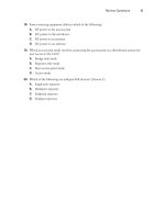
6. Which of the following channels on three co-located access points will result in the
greatest co-channel interference?
A. 1, 1, 1
B. 1, 2, 3
C. 1, 6, 11
C. Access points use two antennas to overcome multipath
D. 1, 11
7. Which one of the following can cause all-band interference?
A. Metal roof
B. Lake
C. Bluetooth
D. HiperLAN
8. Why are most access points built with two antennas?
A. Access points are half-duplex devices that send on one antenna and receive on
the other
B. Access points use one antenna as a standby for reliability
D. Access points use two antennas to transmit on two different channels
9. Using RTS/CTS can solve the hidden node problem and will not affect network
throughput
A. This statement is always true
B. This statement is always false
C. Depends on the manufacturer’s equipment
10. Which of the following can cause RF interference in a wireless LAN? Choose all
that apply.
A. Wind
B. Lightning
C. Smog
D. Clouds
CWNA Study Guide © Copyright 2002 Planet3 Wireless, Inc.
253 Chapter 9 –Troubleshooting Wireless LAN Installations
11. Multipath is defined as which one of the following?
A. The negative effects induced on a wireless LAN by reflected RF signals
arriving at the receiver along with the main signal.
B. Surges in signal strength due to an RF signal taking multiple paths between the
sending and receiving stations
C. The condition caused by a receiving station having multiple antennas which
causes the signal to take multiple paths to the CPU
D. The result of using a signal splitter to create multiple signal paths between
sending and receiving stations
12. Multipath can cause signals to increase above the power of the signal that was
transmitted by the sending station. This statement is:
A. Always true
B. Always false
C. True, when the signal is transmitted in clear weather
D. False, unless a 12 dBi or higher power antenna is being used
13. Multipath is caused by which one of the following?
A. Multiple antennas
B. Wind
C. Reflected RF waves
D. Bad weather
14. When can the hidden node problem occur?
A. Only when a network is at full capacity
B. When all users of a wireless LAN are simultaneously transmitting data
C. Anytime, even after a flawless site survey
D. Every time a wireless LAN client roams from one access point to another
15. Which one of the following is NOT a solution for correcting the hidden node
problem?
A. Using the RTS/CTS protocol
B. Increasing power to the node(s)
C. Removing obstacles between nodes
D. Moving the hidden node(s)
CWNA Study Guide © Copyright 2002 Planet3 Wireless, Inc.
Chapter 9 –Troubleshooting Wireless LAN Installations 254
16. How is the threshold set when using RTS/CTS in "On with Threshold" mode on a
wireless LAN?
A. Automatically by the access points only
B. Manually by the user of the hidden node
C. Manually on the clients and access points by the wireless LAN administrator
D. Automatically by the clients only
D. 802.11a equipment is backwards compatible with 802.11g equipment
17. A situation that results in the client(s) that are farther away from the access point and
using less power to not be heard over the traffic from the closer, high-powered
clients, is known as:
A. Hidden Node
B. Near/Far
C. Degraded throughput
D. Interference
18. Why should an administrator be able to co-locate 3 DSSS access points in the same
area using the 2.4 GHz ISM band?
A. Each access point will transmit on one band and receive on another.
B. Each access point will use co-channel interference to stop the others from
transmitting data when it is ready to send
C. The access points will use channels that do not overlap or cause adjacent
channel interference
D. There are up to five non-overlapping DSSS channels in the ISM bands.
19. How many channels in the 2.4 GHz spectrum are designated for use in the United
States?
A. 3
B. 14
C. 10
D. 11
20. Which one of the following is an advantage of 5 GHz (802.11a) equipment over
802.11b equipment?
A. The lower 5 GHz UNII band is wider than the 2.4 GHz ISM band
B. The 802.11a equipment is less expensive than 802.11b
C. The 5 GHz UNII bands allows for more non-overlapping channels than the 2.4
GHz ISM band
CWNA Study Guide © Copyright 2002 Planet3 Wireless, Inc.
255 Chapter 9 –Troubleshooting Wireless LAN Installations
Answers to Review Questions
1. A, B. Sometimes increasing the power on the nodes is enough to transmit through
or around the obstacle blocking the RF signals from stations and sometimes it is not.
When increasing the power is not enough, the best course of action is use of the
RTS/CTS protocol in order that stations broadcast their intention to transmit data on
the network.
2. D. By having two antennas and supporting antenna diversity, most access points can
overcome multipath problems. Antenna diversity works by separating the two
antennas by a distance greater than the wavelength of the frequency in use thereby
reducing the changes that both spots will have exactly the same detrimental effects
from reflected waves.
3. A. Signal fading can refer to upfade, downfade, or nulling of an RF transmission.
This type of fading is sometimes referred to as Rayleigh fading, but most often it is
simply deemed fading. No matter what type of fading happens, it's generally
detrimental to the main RF wave.
4. B. The delay spread is the amount of time between the arrival at the receiver of the
main RF wave and the arrival of the last reflected wave. This amount of time is
typically 4 nanoseconds or less.
5. A, D. The near/far problem is normally remedied by the wireless protocols in use
such as CSMA/CA. When these protocols are ineffective, increasing power to
remote nodes, moving the remote nodes closer to the local nodes, or decreasing
power to the local nodes are some available remedies.
6. A. Co-channel interference is the interference experienced between systems using
the same channel. In this question, only answer 'A' meets the criteria of all access
points being on the same channel.
7. C. All band interference is interference that spans the width of the frequency band
in use. This type of interference cannot be avoided by a wireless LAN system,
leaving the administrator one option: a different frequency band must be used, which
often means use of a different set of wireless LAN technologies. Bluetooth spans
the width of the 2.4 GHz ISM band disrupting 802.11, 802.11b, and 802.11g data
transmissions.
8. C. Access points use two antennas in order to implement antenna diversity to
overcome multipath. The radios used in wireless LANs are half duplex meaning
they can either transmit or receive at any given time. Multipath is an effect caused
by reflected RF waves and can disrupt or corrupt data transmissions. Access points
sample inputs from both antennas and use the best signal. Access points normally
transmit on the antenna last used for receiving.
9. B. Use of the RTS/CTS protocol always adds overhead to the network, decreasing
throughput. Use of the RTS/CTS protocol, when used appropriately, can help
reduce a high rate of collisions on a wireless network, but does not solve the hidden
node problem. Solving the hidden node problem would consist of all nodes being
able to hear one another’s transmissions.
CWNA Study Guide © Copyright 2002 Planet3 Wireless, Inc.
Chapter 9 –Troubleshooting Wireless LAN Installations 256
10. A, B, C. Wind can load antennas, breaking RF links or at least causing degraded
throughput. Lightning can destroy wireless LAN equipment and can introduce high
levels of RF interference due to power surges around the transmission path between
the transmitter and receiver. Smog can have intermittent effects on wireless LANs
depending on the severity and makeup of the smog. Generally smog causes
degraded throughput for a long-distance RF link.
11. A. Multipath is the set of negative effects that multiple RF signals arriving at the
same destination at almost the same time from the same source has on a wireless
LAN. These reflected signals can have numerous effects on the main signal.
Multipath is especially disruptive when there are many reflective objects in area
around the signal path from transmitter to receiver.
12. B. Due to Free Space Path Loss, an RF wave arriving at a receiver will never be as
strong as the transmitted wave. Multipath can cause an increase in the received
signal over what it would have been had there been no multipath due to reflected
waves being in phase with the main wave, but the main signal will never be
increased in amplitude beyond the transmission power.
13. C. If there were no reflective objective near the signal path between transmitter and
receiver, multipath would not exist. The lack of any reflective object is rarely the
case since anything metal and many smooth things (like a body of water or a flat
stretch of earth) reflect RF waves. Multipath almost always exists in any wireless
LAN connection; hence, the use of dual antennas on most access points.
14. C. The causes of the hidden node problem are numerous. Typical causes are
obstructions through which RF waves cannot penetrate and low power on client
stations. A good site survey might help in reducing the occurrences of hidden node
problems, but eliminating them would only be possible in an unchanging
environment. The main use and advantage of a wireless LAN is mobility, which
creates an ever-changing environment.
15. A. The RTS/CTS protocol is not a cure for the hidden node problem, but a tool used
to reduce the negative effects that hidden nodes have on the network: collisions.
16. C. The network administrator must manually configure the access points and clients
for use of RTS/CTS regardless of the setting. The three settings are Off, On, and On
with Threshold. The Off setting is used by default to reduce unnecessary overhead
on the network.
17. B. The near/far problem is one that is addressed by the access protocols used by
wireless networks. This problem is seen in both cellular and wireless LAN
networks. When the problem is severe, it might be necessary to move distant nodes
closer, increase power to distant nodes, or to decrease power to closer nodes.
18. C. There are three non-overlapping DSSS channels specified by the FCC in the 2.4
GHz ISM band. Each of these bands is separated by 5 MHz. These channels are 1,
6, & 11 as numbered by the FCC.
19. D. The FCC specifies 14 channels for use with wireless LANs, 11 of which can be
used in the United States. Each channel is 22 MHz wide, and the channel is
specified as a center frequency +11 MHz and -11 MHz.
CWNA Study Guide © Copyright 2002 Planet3 Wireless, Inc.
257 Chapter 9 –Troubleshooting Wireless LAN Installations
20. C. The lower 5 GHz UNII band and the 2.4 GHz ISM band are the same width -
100 MHz. 802.11a equipment is new and significantly more expensive than 802.11b
equipment and is not compatible with 802.11b or 802.11g equipment in any
capacity. The UNII bands (all three of them) allow for a larger useable portion than
does the 2.4 GHz ISM band, yielding a maximum of 4 non-overlapping DSSS
channels.
CWNA Study Guide © Copyright 2002 Planet3 Wireless, Inc.
CWNA Study Guide © Copyright 2002 Planet3 Wireless, Inc.
Wireless LAN Security
CWNA Exam Objectives Covered:
Identify the strengths, weaknesses and appropriate uses of the
following wireless LAN security techniques
WEP
AES
Filtering
Emerging security techniques
Describe the following types of wireless LAN security attacks,
and explain how to identify and prevent them
Passive attacks (eavesdropping)
Active attacks (connecting, probing, and configuring the network)
Jamming attacks
Man-in-the-middle attacks
Given a wireless LAN scenario, identify the appropriate security
solution from the following available wireless LAN security
solutions
WEP key solutions
Wireless VPN
Key hopping
AES based solutions
Wireless gateways
802.1x and EAP
Explain the uses of the following corporate security policies and
how they are used to secure a wireless LAN
Securing sensitive information
Physical security
Inventory and audits
Using advanced solutions
Public networks
Identify how and where the following security precautions are
used to secure a wireless LAN
WEP
Cell sizing
Monitoring
User authentication
Wireless DMZ
CHAPTER
5
CHAPTER
10
In This Chapter
WEP
Filtering
Attacks
Emerging Solutions
Corporate Security Policy
Security Recommendations
Chapter 10 – Wireless LAN Security 260
Wireless LANs are not inherently secure; however, if you do not take any precautions or
configure any defenses with wired LAN or WAN connections, they are not secure either.
The key to making a wireless LAN secure, and keeping it secure, is educating those who
implement and manage the wireless LAN. Educating the administrator on basic and
advanced security procedures for wireless LANs is essential to preventing security
breaches into your wireless LAN.
In this very important chapter, we will discuss the much-maligned 802.11 specified
security solution known as Wired Equivalent Privacy, or WEP. As you may already
know, WEP alone will not keep a hacker out of a wireless LAN for very long. This
chapter will explain why, and offer some steps for how WEP can be used with some level
of effectiveness.
We will explain the various methods that can be used to attack a wireless LAN so that as
an administrator you will know what to expect and how to prevent it. Then we will
discuss some of the emerging security solutions that are available, but not yet specified
by any of the 802.11 standards. Finally, we will offer some recommendations for
maintaining wireless LAN security and discuss corporate security policy as it pertains
specifically to wireless LANs.
This chapter on wireless LAN security is by no means the end of knowledge on the
subject. Rather, this chapter should serve the CWNA candidate as a basic introduction to
the inherent weaknesses of wireless LANs and the available solutions for compensating
for these weaknesses.
Wired Equivalent Privacy (WEP) is an encryption algorithm used by the Shared Key
authentication process for authenticating users and for encrypting data payloads over only
the wireless segment of the LAN. The IEEE 802.11 standard specifies the use of WEP.
WEP is a simple algorithm that utilizes a pseudo-random number generator (PRNG) and
the RC4 stream cipher. For several years this algorithm was considered a trade secret and
details were not available, but in September of 1994, someone posted the source code in
the cypherpunks mailing list. Although the source code is now available, RC4 is still
trademarked by RSADSI. The RC4 stream cipher is fast to decrypt and encrypt, which
saves on CPU cycles, and RC4 is also simple enough for most software developers to
code it into software.
Wired Equivalent Privacy
When WEP is referred to as being simple, it means that it is weak. The RC4 algorithm
was inappropriately implemented in WEP, yielding a less-than-adequate security solution
for 802.11 networks. Both 64-bit and 128-bit WEP (the two available types) have the
same weak implementation of a 24-bit Initialization Vector (IV) and use the same flawed
process of encryption. The flawed process is that most implementations of WEP
initialize hardware using an IV of 0 - thereafter incrementing the IV by 1 for each packet
sent. For a busy network, statistical analysis shows that all possible IVs (2
24
) would be
exhausted in half a day, meaning the IV would be reinitialized starting at zero at least
once a day. This scenario creates an open door for determined hackers. When WEP is
CWNA Study Guide © Copyright 2002 Planet3 Wireless, Inc.
261 Chapter 10 – Wireless LAN Security
used, the IV is transmitted in the clear with each encrypted packet. The manner in which
the IV is incremented and sent in the clear allows the following breaches in security:
Active attacks to inject new traffic- Unauthorized mobile stations can inject
packets onto the network based on known plaintext
Active attacks to decrypt traffic - Based on tricking the access point
Dictionary-building attacks - After gathering enough traffic, the WEP key can be
cracked using freeware tools. Once the WEP key is cracked, real-time
decryption of packets can be accomplished by listening to broadcasts packets
using the WEP key
Passive attacks to decrypt traffic - Using statistical analysis, WEP traffic can be
decrypted.
Why WEP Was Chosen
Since WEP is not secure, why was it chosen and implemented into the 802.11 standard?
Once the 802.11 standard was approved and completed, the manufacturers of wireless
LAN equipment rushed their products to market. The 802.11 standard specifies the
following criteria for security:
Exportable
Reasonably Strong
Self-Synchronizing
Computationally Efficient
Optional
WEP meets all these requirements. When it was implemented, WEP was intended to
support the security goals of confidentiality, access control, and data integrity. What
actually happened is that too many early adopters of wireless LANs thought that they
could simply implement WEP and have a completely secure wireless LAN. These early
adopters found out quickly that WEP wasn't the complete solution to wireless LAN
security. Fortunately for the industry, wireless LAN hardware had gained immense
popularity well before this problem was widely known. This series of events led to many
vendors and third party organizations scrambling to create wireless LAN security
solutions.
The 802.11 standard leaves WEP implementation up to wireless LAN manufacturers, so
each vendor’s implementation of WEP keys may or may not be the same, adding another
weakness to WEP. Even WECA's Wi-Fi interoperability standard tests include only 40-
bit WEP keys. Some wireless LAN manufacturers have chosen to enhance (fix) WEP,
while others have looked to using new standards such as 802.1x with EAP or Virtual
Private Networks (VPN). There are many solutions on the market addressing the
weaknesses found in WEP.
CWNA Study Guide © Copyright 2002 Planet3 Wireless, Inc.
Chapter 10 – Wireless LAN Security 262
WEP Keys
The core functionality of WEP lies in what are known as keys, which are the basis for the
encryption algorithm discussed in the previous section of this chapter. WEP keys are
implemented on client and infrastructure devices on a wireless LAN. A WEP key is an
alphanumeric character string used in two manners in a wireless LAN. First, a WEP key
can be used to verify the identity of an authenticating station. Second, WEP keys can be
used for data encryption.
When a WEP-enabled client attempts to authenticate and associate to an access point, the
access point will determine whether or not the client has the correct WEP key. By
“correct”, we mean that the client has to have a key that is part of the WEP key
distribution system implemented on that particular wireless LAN. The WEP keys must
match on both ends of the wireless LAN connection.
As a wireless LAN administrator, it may be your job to distribute the WEP keys
manually, or to setup a more advanced method of WEP key distribution. WEP key
distribution systems can be as simple as implementing static keys or as advanced as using
centralized encryption key servers. Obviously, the more advanced the WEP system is,
the harder it will be for a hacker to gain access to the network.
WEP keys are available in two types, 64-bit and 128-bit. Many times you will see them
referenced as 40-bit and 104-bit instead. This reference is a bit of a misnomer. The
reason for this misnomer is that WEP is implemented in the same way for both
encryption lengths. Each uses a 24-bit Initialization Vector concatenated (linked end-to-
end) with a secret key. The secret key lengths are 40-bit or 104-bit yielding WEP key
lengths of 64 bits and 128 bits.
Entering static WEP keys into clients or infrastructure devices such as bridges or access
points is quite simple. A typical configuration program is shown in Figure 10.1.
Sometimes there is a checkbox for selecting 40- or 128-bit WEP. Sometimes no
checkbox is present, so the administrator must know how many characters to enter when
asked. Most often, client software will allow inputting of WEP keys in alphanumeric
(ASCII) or hexadecimal (HEX) format. Some devices may require ASCII or HEX, and
some may take either form of input.
There are many HEX-ASCII conversion charts on the Internet that can be found with a
simple search engine. You might have to reference such a chart if using mixed vendor
hardware across your network. Some vendors include this conversion chart in their
client software's HELP section.
CWNA Study Guide © Copyright 2002 Planet3 Wireless, Inc.
263 Chapter 10 – Wireless LAN Security
FIGURE 10.1 Entering WEP keys on client devices
The number of characters entered for the secret key depends on whether the configuration
software requires ASCII or HEX and whether 64-bit or 128-bit WEP is being used. If
your wireless card supports 128-bit WEP, then it automatically supports 64-bit WEP as
well. If entering your WEP key in ASCII format, then 5 characters are used for 64-bit
WEP and 13 characters are used for 128-bit WEP. If entering your WEP key in HEX
format, then 10 characters are used for 64-bit WEP and 26 characters are used for 128-bit
WEP.
Static WEP Keys
If you choose to implement static WEP keys, you would manually assign a static WEP
key to an access point and its associated clients. These WEP keys would never change,
making that segment of the network susceptible to hackers who may be aware of the
intricacies of WEP keys. For this reason, static WEP keys may be an appropriate basic
security method for simple, small wireless LANs, but are not recommended for enterprise
wireless LAN solutions.
When static WEP keys are implemented, it is simple for network security to be
compromised. Consider if an employee left a company and "lost" their wireless LAN
card. Since the card carries the WEP key in its firmware, that card will always have
access to the wireless LAN until the WEP keys on the wireless LAN are changed.
Most access points and clients have the ability to hold up to 4 WEP keys simultaneously,
as can be seen in Figure 10.2. One useful reason for having the ability to enter up to 4
WEP keys is network segmentation. Suppose a network had 100 client stations. Giving
out four WEP keys instead of one could segment the users into four distinct groups of 25.
CWNA Study Guide © Copyright 2002 Planet3 Wireless, Inc.