Optimizing and Testing WLANs phần 6 docx
Bạn đang xem bản rút gọn của tài liệu. Xem và tải ngay bản đầy đủ của tài liệu tại đây (1.04 MB, 26 trang )
Protocol Testing
117
Secondly, there are four distinct encryption modes (none, WEP, TKIP, and AES-CCMP).
Again, if the test equipment and DUT permit, the four modes can be set up and run in turn
without operator involvement. However, most WLAN APs require manual intervention to
switch them from one encryption mode to another, so it is possible that the four modes will be
tested in sequence (i.e., treated as four separate test runs). This source of manual overhead can
be avoided if the DUT itself can be confi gured from the same script that drives the tester.
Finally, the test must be performed with traffi c fl owing in the wireless-to-Ethernet,
the Ethernet-to-wireless, and both directions. There are hence a very large number of
combinations (1455 ϫ 4 ϫ 3 ϭ 17460 in all). After all of this has been comprehended, the
sheer number of combinations will usually cause the QA department to realize that this is an
excellent candidate for a scripted, automated test.
The script that is created should perform a traffi c forwarding test at each of the combinations
of test conditions (referred to as a trial). Basically, the script sets up the test equipment to
generate traffi c having the desired frame size, encryption mode, and traffi c direction, and
then starts the traffi c fl owing; after a specifi c trial duration or a pre-set number of transmitted
frames, the script stops the traffi c and measures the difference between the number of frames
transmitted to the DUT and the number of frames received from the DUT, which should be
zero if the trial has succeeded. Once the trial has completed, a new set of test conditions –
frame size, encryption mode, and traffi c direction – is selected and the equipment set up
accordingly, and the next trial is run.
A single functional test like the above can take quite a long time to complete, even if it is
scripted. However, by the same token it also exercises a great deal of DUT functionality in
a single test, and can therefore expose many bugs and issues before the product is released.
Many such functional tests are grouped to create a vendor’s QA test plan, which is run on
every product version prior to making it available to customers. As can be imagined, the time
taken to complete a test plan for a product such as an AP can range from several weeks to
several months, depending on the complexity of the product and the level of quality required.
5.3 Interoperability Testing
Interoperability testing is diametrically opposed to both functional and performance testing.
The latter is normally carried out with specialized test equipment, and tests the DUT in
isolation; that is, the test equipment strives as far as possible to avoid affecting either the test
results or the behavior of the DUT. Interoperability testing, however, is done using the actual
peer devices that the DUT will work with in the customer’s environment. For example, an
AP manufacturer would carry out interoperability testing with all of the client adapters (or
at least as many as possible) that are expected to interwork with his or her AP. Conversely, a
client chipset vendor would try to test their chipset reference design against as many different
commercially available APs as made sense.
Ch05-H7986.indd 117Ch05-H7986.indd 117 6/28/07 10:16:22 AM6/28/07 10:16:22 AM
Chapter 5
118
Obviously, both the DUT and the peer device will affect the test results; in fact, sometimes
the behavior of the peer device can have a greater impact on the results than the DUT
itself. Hence, the results of an interoperability test performed against one peer device
frequently do not have any relationship to the results of the identical interoperability test
performed against another peer device. Thus, when quoting the results of an interoperability
test, it is necessary to describe not only the DUT but also the peer device against which it is
tested.
5.3.1 Why Test Interoperability?
One might expect that a suffi ciently detailed set of functional and conformance tests would
be enough to fully qualify a DUT. After all, if the DUT completely conforms to the IEEE
802.11 standard, and also fi lls all the requirements of the datasheet, why is it necessary to test
it against other commercial devices?
Much of the wired LAN world in fact does operate this way; instead of performing ever more
exhaustive interoperability tests on ever increasing combinations of Ethernet devices, the
Ethernet industry simply requires that all vendors verify compliance to the Ethernet (IEEE
802.3) standard. As the Ethernet standard is simple and well-understood, it is relatively
straightforward to guarantee interoperability in this fashion. The fact that Ethernet “just
works” is a testament to a single-minded focus on interoperability and simplicity by the IEEE
802.3 standards committee.
The WLAN protocol suite, however, is a different animal altogether. The WLAN MAC and
security protocols are quite a bit more complex than Ethernet, and contain a very large number
of moving parts. (As a comparison, the 802.3 standard requires just 66 pages to fully specify
the Ethernet MAC, but the corresponding portion of the 802.11 standard, including security
and Quality of Service (QoS), occupies more than 400!) Further, there is considerable latitude
for implementers to introduce their own “creativity” and – in some cases – misinterpretations.
All of this conspires against interoperability.
Wireless LAN manufacturers therefore have little choice but to verify interoperability by
experiment. All vendors maintain large collections of peer devices – client adapters in the
case of AP vendors, APs in the case of client vendors – against which each of their products is
extensively tested.
5.3.2 Interoperability vs. Performance
It has been noted previously that functional tests are often confused for performance tests
and vice versa. In the same vein, interoperability tests sometimes masquerade as performance
tests, particularly when the test results are quantitative measures of things like traffi c
forwarding rate that are of intense interest to the marketing department.
Ch05-H7986.indd 118Ch05-H7986.indd 118 6/28/07 10:16:22 AM6/28/07 10:16:22 AM
Protocol Testing
119
One of the most crucial requirements of a successful performance test is that the test
equipment and test setup should have as little infl uence as possible on the measured results.
(One could regard this as a sort of Heisenberg principle of testing; if tester imperfections
affect the measurement to a perceptible degree, then it is unclear as to whether it is the DUT
or the test equipment that is being tested.) Designers of commercial protocol test equipment
go to extreme lengths to ensure that their equipment is as close to being “invisible” to the
DUT as permitted by the protocol standard. The test results are hence valid in the absolute
sense, in that they represent a physical property of the DUT as a stand-alone device.
This is certainly not the case for interoperability tests, which have a quite different underlying
philosophy and purpose. A traffi c forwarding rate test performed between a specifi c AP and
a specifi c client produces a result that is only valid for that particular combination of AP
and client; substituting a different client but keeping the AP the same, is highly unlikely to
produce the same result. Therefore, any test involving a “real” AP and a “real” client must be
regarded as an interoperability test, and the results should be treated as being valid for only
that combination. It is a mistake to assume that the results are valid for the AP in isolation;
interoperability tests should be used only in a relative sense.
5.3.3 The Wi-Fi® Alliance Interoperability Tests
Interoperability tests are not the sole province of WLAN equipment vendors; the Wi-Fi®
Alliance, an industry marketing and certifi cation group, maintains and performs a large set
of what are basically interoperability tests before certifying a WLAN chipset or device as
“Wi-Fi® certifi ed”. A standardized set of four reference clients is used to test AP devices, and
another standardized set of four reference APs is used for clients.
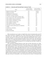
Wi-Fi® Alliance interoperability tests cover many different areas: basic performance, security
(WPA and WPA2), QoS (WMM and WMM-SA), Voice over IP (VoIP), hot-spots, etc. Most of
them are intended to be conducted with a low cost and fairly standardized test setup, shown in
the fi gure below.
For each subject area, the Wi-Fi® Alliance builds a set of compliance and interoperability
test procedures around the above setup, in order to verify basic standards compatibility of the
equipment as well as to determine if one vendor’s equipment will communicate with another.
Originally, the Wi-Fi® Alliance was concerned solely with ensuring equipment
interoperability. (In fact, it was formerly known as the Wireless Ethernet Compatibility
Alliance, or WECA, refl ecting this intended role.) However, as 802.11 WLANs have increased
in both market size and capability, the Wi-Fi® Alliance has correspondingly expanded its
charter. It now includes such activities as marketing and “802.11 public relations”, defi ning
profi les – subsets of planned or current 802.11 MAC protocol functionality – to be used by
early implementations, and sometimes even creating new 802.11 MAC protocols in advance
of the actual standardization by the IEEE.
Ch05-H7986.indd 119Ch05-H7986.indd 119 6/28/07 10:16:23 AM6/28/07 10:16:23 AM
Chapter 5
120
5.3.4 The Interoperability Test Process
Unlike functional or performance tests, interoperability testing involves two DUTs – in the
case of WLANs, this is typically an AP and a client device such as a laptop or handheld. It
is not particularly useful to single out either one of the devices. Instead, the pair of DUTs is
treated as a single system under test.
Apart from the DUTs, the test setup requires some means of generating traffi c, and some
means of analyzing it. In the case of the Wi-Fi® Alliance tests, a software traffi c generator
such as Chariot is used, along with a software traffi c analyzer such as AirMagnet or Airopeek.
In addition, an isolated environment (a conducted setup, a chamber or a screened room) is
strongly recommended for repeatability’s sake. However, as the test results are not
particularly precise, engineers performing interoperability tests frequently conduct them in the
open air.
WIRELESS
ACCESS
POINT
WIRELESS
ACCESS
POINT
WIRELESS
ACCESS
POINT
WIRELESS
ACCESS
POINT
Reference AP
#1
Reference AP
#2
Reference AP
#3
Reference AP
#4
Replaced
by DUT
when AP
is being
tested
Reference
client #1
Reference
client #2
Reference
client #3
Reference
client #4
Wireless
Sniffer
Switched
Ethernet
Backbone
Chariot
Test
Software
Server
RADIUS
Security
Server
Ethernet
Sniffer
Interoperability Matrix
Replaced by
DUT when
client is
being tested
Figure 5.3: Wi-Fi® Alliance Interoperability Test Setup
Ch05-H7986.indd 120Ch05-H7986.indd 120 6/28/07 10:16:23 AM6/28/07 10:16:23 AM
Protocol Testing
121
The test process is quite simple. The two DUTs are confi gured into the desired mode,
associated with each other, and then the traffi c generator is used to inject a stream of test
traffi c into one of the DUTs. The sniffer or traffi c analyzer captures the resulting output traffi c
from the other DUT. A post-analysis phase yields test results, such as the packet forwarding
rate of the DUT combination, that indicate interoperability. If the test is performed with
several combinations of DUTs (as in the case of the Wi-Fi® Alliance test suites) then a large
matrix of results is produced, representing the different combinations.
5.4 Performance Testing
Performance testing is valued more highly than any other form of measurement within the
networking industry (and in others as well, notably microprocessor technology). Most LAN
users are not particularly concerned about whether their equipment meets the standard as
long as it generally works, but almost all of them are deeply interested in how well it works.
Performance tests are designed to answer that question.
The performance of networking gear may be measured along many different axes; some
are purely objective (such as “throughput”), while others are subjective (such as
“manageability”). For obvious reasons, this book will concern itself only with objective
performance metrics. Examples of such metrics are throughput, latency, client capacity,
roaming delay, etc.
In addition, note that PHY layer performance has a signifi cant impact on the perceived
capabilities of equipment. As an example, a WLAN client adapter with a signifi cantly better
radio will obviously provide a higher range than other adapters. However, these metrics have
already been dealt in Chapter 4 (see Section 4.5). This chapter focuses on performance metrics
that are relevant to the MAC and other packet processing layers.
5.4.1 Performance Test Setups
Performance test setups are not unlike functional test setups, in that in their simplest form they
can be reduced to two elements: a DUT and a tester. However, users rarely have the luxury of
confi ning themselves to something so uncomplicated. Actual performance test setups involve
additional equipment, particularly if the tests are carried out in the open air.
Open air performance test setups involve little in the way of RF plumbing, and are closest
to the normal “use model” (i.e., how a consumer or end-user would use the DUT) and hence
are quite widely used. However, the caveats in Section 3.3 apply, and should be religiously
observed. It is very easy for a poorly managed open-air test to produce utterly useless results
when unsuspected interference or adjacent WLANs are present. At a minimum, the use of a
good wireless “sniffer” to detect co-located networks and form a rough estimate of the local
noise level is mandatory. Adding a spectrum analyzer to the mix is also highly recommended;
Ch05-H7986.indd 121Ch05-H7986.indd 121 6/28/07 10:16:23 AM6/28/07 10:16:23 AM
Chapter 5
122
a spectrum analyzer can detect and display non-coherent interference sources (e.g., the
proverbial microwave oven) that can seriously affect the test results.
One factor in open-air testing that is often overlooked is the need to account for the
antenna radiation patterns of both the DUT and the tester. For example, the DUT
(particularly if it is an AP) may be equipped with a supposedly omnidirectional vertical
antenna; however, unless this antenna is located in the center of a large fl at horizontal
sheet of metal, it is unlikely to have an omnidirectional radiation pattern. (A laptop or
handheld does not even pretend to have an omnidirectional pattern!) Some directions will
therefore provide higher gain than others; a side-mounted or rear-mounted vertical antenna
can have up to 10 dB of variation between minimum and maximum gain directions (i.e.,
front-to-back or front-to-side ratio). Further, coupling to power or network cables can produce
further lobes in the radiation pattern in all three dimensions. What this effectively translates
to is that rotating the DUT or the tester even slightly, or translating it in the horizontal or
vertical directions, can cause relatively large variations in signal strength and hence affect the
performance.
To eliminate the antenna radiation patterns as a source of uncertainty (at least in the horizontal
direction), turntables are used. The DUT and tester are placed on turntables and rotated in
small steps, typically 10º or 15º increments. The performance measurements are repeated at
each step, and the fi nal result is expressed as the average of all the measurements. This leads
to a much more repeatable measurement result.
Conducted test setups are more complex and require RF plumbing. The key factors here
are obtaining adequate isolation, while at the same time ensuring that the right levels of RF
signals are fed to the various devices. Frequently, more than just the DUT and the tester
are involved; for example, additional sniffers to capture and analyze wireless traffi c, power
meters to determine the exact transmit signal levels from the DUT, vector signal analyzers to
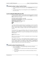
Figure 5.4: Typical Performance Test Setups
Open-Air Test Area
Spectrum
Analyzer
Traffic
Generator and
Analyzer (TGA)
DUT
Measurement
Antenna
WIRELESS
ACCESS POINT
Probe
Antenna
Traffic Generator and Analyzer (TGA)
WIRELESS
ACCESS POINT
Isolation
Chamber
DUT
Filtered Ethernet
Data Connection
Filtered Serial
Control
Connection
Host Computer with
Test Software
RF
Over-the-air (open-air) Performance Test Setup
Conducted Performance Test Setup
Attenuator
(20–30dB)
2:1 Splitter
Host Computer with
Test Software
Ch05-H7986.indd 122Ch05-H7986.indd 122 6/28/07 10:16:23 AM6/28/07 10:16:23 AM
Protocol Testing
123
measure the signal quality from the DUT, variable attenuators for signal level adjustment, and
so on, may be used in the same test setup. Fixed attenuators, high-quality RF cables, properly
terminated splitters, and good shielded enclosures are all essential components of a conducted
test setup. The reader is referred to Section 3.5 for more details.
5.4.2 Goals of Performance Testing
Performance tests, if carried out properly, seek to quantify certain specifi c performance
metrics. The goal of a performance test is therefore to use a test plan to measure and report a
metric. It should thus be obvious that there are two essential components to every performance
test: a well-defi ned metric, and a well-executed test plan to quantify that metric. Missing one
or the other generally results in a lot of wasted effort.
A “metric” refers to the quantity or characteristic that is being measured. More time and
energy is wasted on a poorly defi ned metric than on any other cause. The importance of
knowing exactly what is to be measured, and being able to describe all of the test conditions
that must be set up before measuring it, cannot be overstated. An additional requirement that
is often overlooked is the need to form an abstract “model” of how the DUT affects the metric
being measured. Without such a model, the test conditions cannot be properly defi ned, and the
fi nal measurement cannot be sanity-checked.
To take a specifi c example, consider the problem of measuring the latency through the DUT.
The fi rst task is defi ning “latency”. On the face of it, this seems quite simple: latency is merely
the delay through the DUT – basically, transmit a packet to the DUT and have the tester
measure the time taken before the same packet is received.
However, there are some issues. Firstly, a packet contains a number of data bits, and thus takes
a fi nite amount of time to transfer. Do we measure the delay starting from the fi rst bit of the
transmitted packet, or the last bit? The same dilemma applies to the received packet. In fact,
there are four measurements possible: fi rst transmitted bit to fi rst received bit, fi rst transmitted
bit to last received bit, last transmitted bit to fi rst received bit, and last transmitted bit to last
received bit. Which one is correct?
For this, we turn to RFC 1242 (which deals with benchmarking terminology), which states
that for store-and-forward devices, which includes WLAN equipment, the latency is measured
from the last bit of the transmitted frame to the fi rst bit of the received frame.
Another important question to answer for the latency measurement is: at what rate should we
transmit packets to the device? If the rate of transmission is low (e.g., 1 packet per second),
then the DUT may turn in an artifi cially low latency number; after all, real networks do not
have such low traffi c loads. On the other hand, if the packet rate is too high, then the internal
buffers in the DUT will fi ll up (and possibly overfl ow), in which case we will wind up
Ch05-H7986.indd 123Ch05-H7986.indd 123 6/28/07 10:16:25 AM6/28/07 10:16:25 AM
Chapter 5
124
measuring the buffer occupancy delays in the DUT, not the intrinsic packet forwarding delay.
The proper selection of a traffi c load level for a latency test is thus quite signifi cant. Typically,
a throughput test is performed on the DUT, and the traffi c load is set to 50% to 90% of the
measured throughput.
Clearly, even the simplest tests can involve a number of factors, along with some knowledge
of how the DUT is constructed. Forming a model of the DUT and applying it to the metric
in order to properly specify and control the test conditions is one of the key challenges of
performance measurement.
Once the metric has been defi ned and the test conditions have been specifi ed, the next issue is
creating a suitable test plan. In essence, the performance test plan is a recipe – it specifi es the
equipment that will be used, shows how the equipment will be connected, defi nes the various
settings for both the DUT and the test equipment, and then gives the procedure for actually
conducting the test. (Most good test plans, like most good recipes, also contain instructions for
how to present the results.) It is important to write all this down and follow it exactly, in order
to produce repeatable results.
A little-understood detail in the process of constructing a performance test plan is
quantifying the error bounds for the test. The error bounds basically defi ne the uncertainty
of the test results; for instance, if the error bounds for a latency test were ϩ/Ϫ5%, then a
measured latency value of 100 μs could be as much as ϩ/Ϫ5 μs in error (i.e., the true latency
value could be anywhere between 95 and 105 μs). Error bounds are very useful in
determining if the test results are valid; for example, if the calculated error bounds for a
test are ϩ/Ϫ5%, but the actual run-to-run measurements vary by ϩ/Ϫ20%, then clearly
something is wrong. The process of determining the error bounds for most protocol
performance tests is, unfortunately rather cumbersome, especially due to the complex
interactions involved between DUT and tester. Nevertheless, an effort should be made to
quantify it, if at all possible.
5.4.3 Performance Test Categories
Protocol-level performance tests can be generally categorized into three types: rate-based
metrics, time-based metrics, and capacity metrics. All three types are of interest when
measuring the performance of WLAN devices.
Rate-based metrics measure parameters such as throughput, that are essentially the rates
at which events occur. Time-based metrics, on the other hand, measure in terms of time
intervals; packet latency is an example of a time-based metric. Capacity metrics, along various
dimensions, measure amounts; for example, the buffer capacity of a WLAN switch measures
the number of packets that the switch can store up during congestion situations before it is
forced to drop one.
Ch05-H7986.indd 124Ch05-H7986.indd 124 6/28/07 10:16:25 AM6/28/07 10:16:25 AM
Protocol Testing
125
5.4.4 Rate-based Metrics
Rate-based metrics are the most well-known performance metrics, as they relate directly to
things such as network bandwidth that interest end-users the most. Rate-based metrics include:
• throughput,
• forwarding rate (both unicast and multicast),
• frame loss rate,
• association rate.
The difference between throughput and forwarding rate is subtle and often mistaken (or
misrepresented!). The best defi nition of “throughput” may be found in RFC 1242: to quote,
it is the maximum traffi c rate at which none of the offered frames are dropped by the device.
Thus the frame loss rate must be zero when the traffi c rate is equal to the throughput.
Forwarding rate, on the other hand, as defi ned in RFC 2285, does not have the “zero loss”
requirement; the forwarding rate is merely the number of frames per second that the device is
observed to successfully forward, irrespective of the number of frames that it dropped (i.e., did
not successfully forward) in the process. A variant of this metric is the maximum forwarding
rate, which is the highest forwarding rate which can be measured for the device. The basic
difference between whether a metric represents throughput or represents forwarding rate
therefore lies in whether frames were dropped or not.
Another source of confusion in rate-based testing stems from the terms “intended load” and
“offered load”. The intended load is the traffi c rate that the tester tried to present to the DUT;
typically, this is the traffi c rate that the user requested, or that the test application confi gured.
Offered load, however, is the packet rate that the tester was actually able to transmit to the
DUT. The offered load can never be greater than the intended load, but may be less. If the
tester is functioning properly, a lower offered load results only from physical medium limits –
that is, the PHY layer is simply not capable of transmitting any more packets than the
measured offered load.
Throughput, forwarding rate and frame loss rate are common metrics, applicable to both wired
and wireless DUTs. Association rate, however, is specifi c to WLAN DUTs; it measures the
rate at which one or more clients can associate with an AP.
5.4.5 Time-based Metrics
Time-based metrics are less signifi cant for data applications (after all, few people are
concerned with whether it takes 1 or 2 ms to download an e-mail message), but are far more
signifi cant for voice and video traffi c. In fact, for voice traffi c, the level of bandwidth is
relatively unimportant (as a voice call occupies only a fraction of the 20 Mb/s capacity of a
Ch05-H7986.indd 125Ch05-H7986.indd 125 6/28/07 10:16:25 AM6/28/07 10:16:25 AM
Chapter 5
126
WLAN link), but the delay and jitter of the traffi c has a huge impact on the perceived quality
of the call.
Time-based metrics include, among many others:
• latency,
• jitter,
• reassociation time.
As WLAN APs and switches are universally store-and-forward devices, latency is
normally measured from the last bit of the frame transmitted to the DUT to the fi rst bit
of the corresponding frame received from the DUT (see Section 5.4.2). It is typical to
measure latencies by specially marking individual packets in the transmitted traffi c from
the tester (referred to as timestamping the traffi c, and often accomplished by inserting a
proprietary signature into the packet payloads containing identifi cation fi elds) and then
measuring the time difference between transmit and receive. It is common to average the
measured latency over a large number of packets in order to obtain a better estimate of the
DUT performance.
Jitter is a measure of the variation in the latency, and is of great interest for real-time traffi c
such as video and voice. Different jitter metrics have been defi ned: peak-to-peak jitter, RMS
jitter, interarrival jitter, etc. The jitter metric commonly used in LAN testing is defi ned in RFC
3550 (the Real Time Protocol specifi cation), and is referred to as smoothed interarrival jitter.
It is, in essence, the variation in delay from packet to packet, averaged over a small window of
time (16 packet arrivals).
Reassociation time is unique to WLANs; this is the time required for a WLAN client to
reassociate with an AP after it has disconnected (or disassociated) from it, or from another AP.
This is important measure of the time required for a network to recover from a catastrophic
event (e.g., the loss of an AP, requiring that all clients switch over to a backup AP).
5.4.6 Capacity Metrics
Capacity metrics deal with amounts, and are mostly applicable only to WLAN infrastructure
devices such as switches and APs. A classical example of a capacity metric is the association
database capacity of an AP. APs need to maintain connection state for all of the clients that
are associated with them; the upper bound on the number of clients that can connect to the
same AP is therefore set by its association database capacity. (Of course, other factors such as
bandwidth and packet loss also kick in when sizeable amounts of traffi c are generated.)
Other capacity metrics include burst capacity and power-save buffer capacity. Burst capacity
is the ability of an AP or switch to accept back-to-back bursts of frames and buffer them up
Ch05-H7986.indd 126Ch05-H7986.indd 126 6/28/07 10:16:25 AM6/28/07 10:16:25 AM
Protocol Testing
127
for subsequent transmission; this is important because LAN traffi c exhibits highly bursty
characteristics, and it is essential to be able to deal with traffi c bursts and ensure that frames
are not lost. Power-save buffer capacity is a similar metric, measuring the APs ability to
buffer frames destined for its clients, but in this case involves WLAN clients that are
alternating between sleep and wake modes and thus have periods where they cannot accept
traffi c. (Sleep mode is used for conserving battery life in laptops, handsets, and Personal
Digital Assistants (PDAs).)
5.4.7 Scalability Testing
Large enterprises usually require correspondingly large WLAN installations. For instance,
a typical large offi ce building might serve a thousand users, using two to three hundred
APs and perhaps a half-dozen WLAN switches. Both the IT staff and their equipment
vendors are interested in ensuring that such a large network stays up and performs well under
all kinds of traffi c loads, sometimes on a 24-hour-a-day, 7-days-a-week basis. A variation
of performance testing is performed to ensure this, falling under the category of scalability
testing.
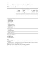
Scalability testing basically involves building out a substantial network topology – in
many cases using exactly the same devices that are expected to be deployed in the actual
“production” network – and subjecting it to a variety of performance and stress tests. For
example, a network vendor, in order to prove to a customer that their equipment will not
fall down, might create a full-blown LAN: 50–100 APs, 5–6 WLAN switches, 2–3 Ethernet
routers, DHCP servers, Remote Authentication Dial-In User Service (RADIUS) authentication
servers, fi le servers, WAN gateways, VoIP call servers, etc. The LAN is then subjected to
simulated traffi c to exercise its functionality and capacity. (Obviously, packing a thousand
users into a building in order to test the LAN with “live” traffi c is not very feasible!) Various
performance tests – throughput, latency, client capacity – are run on the entire LAN, to verify
that the scaled-up LAN works as well as its individual components.
Scalability testing gets particularly important when WLANs are applied to “mission critical”
applications. For example, having a WLAN in the lobby go down is merely a nuisance.
However, if a WLAN is serving the corporate phone system and carrying traffi c from VoIP/
WLAN handsets, it becomes a disaster. Scalability testing is essential for avoiding such
disasters.
It is usually not necessary to reserve an entire building for scalability tests (i.e., in order to
physically deploy the APs and the traffi c simulators in an over-the-air environment). Over-
the-air scalability tests become rapidly more expensive and impractical as the size of the
network is increased. Instead, scalability testing is most easily performed with a fully cabled
setup. As the performance of the infrastructure is being measured, rather than the behavior
of the RF channel or the coverage of the APs, there is very little loss in terms of “realism” or
Ch05-H7986.indd 127Ch05-H7986.indd 127 6/28/07 10:16:26 AM6/28/07 10:16:26 AM
Chapter 5
128
network stress. Obviously, realizing the measured performance in actual practice is dependent
on proper deployment installation practices (covered in a later section), but with modern
equipment and good site planning this is no longer an issue.
5.4.8 Roaming performance
A unique characteristic of WLANs (and, in fact, one that endears them to users in the fi rst
place) is that their users are not static, tethered to desks by cables. Instead, they move about
from place to place. Mobility testing in various forms is a key component to quantifying the
performance of WLAN equipment.
A clarifying note is necessary here, for the benefi t of those familiar with terminology in the
cellular industry. The WLAN industry refers to the process of clients moving from one AP
to another in the same LAN as “roaming”. However, this is equivalent to cellular handsets
moving from one basestation to the next, within the network of the same service provider – a
process which the cellular industry refers to as “handoff” or “handover”. Roaming, as used in
the cellular industry, refers instead to the process of connecting to the network of a different
service provider – i.e. a different network altogether. Roaming in WLANs is therefore
equivalent to handover in cellular networks.
Figure 5.5: Large-Scale Performance Testing
System Under Test
Traffic Generator
and Analyzer (TGA)
Host
Computer
with Test
Software
APs in
Isolation
Chambers
Security
Servers
DHCP
Servers
VoIP
Servers
WLAN
Switches
WLAN
Switches
WLAN
Switches
Switched
Ethernet LAN
Infrastructure
Switched
Ethernet LAN
Infrastructure
Switched
Ethernet LAN
Infrastructure
Traffic Generator
and Analyzer (TGA)
Traffic Generator
and Analyzer (TGA)
Routers
AP
AP
AP
AP AP AP AP AP
AP AP AP AP AP AP AP
Ch05-H7986.indd 128Ch05-H7986.indd 128 6/28/07 10:16:26 AM6/28/07 10:16:26 AM
Protocol Testing
129
Roaming performance is characterized by several metrics:
• average roaming delay,
• packet loss during roaming,
• dropped connections.
The average roaming delay is simply the time required for the client to disconnect from
one of the APs and reconnect to another one. The roaming delay is typically measured in
terms of the arrival times of specially marked or timestamped data packets, so as to establish
exactly when the client disconnected or reconnected. Roaming delays can range from the
small (10–20 ms) to quite large values (several hundred milliseconds) depending on the
security mode employed. In fact, a roaming test is a fairly strenuous test of the security
infrastructure.
Measuring the packet loss during roaming is of interest because it quantifi es the DUT’s ability
to hide roaming artifacts from upper-layer (i.e., TCP/IP) protocols. A typical roaming delay
of 50 ms can represent a considerable number of TCP segments, if the roaming process occurs
in the middle of a fi le transfer. The ability of the client or the WLAN switch to hide the delay
and prevent packet loss from triggering large-scale retransmissions and slowdowns at the TCP
layer is fairly important to good end-user experience.
The most catastrophic outcome of a botched roaming process (at least, from the user’s point
of view) is a dropped connection or failed roam. This manifests itself as the complete failure
to resume normal data transfer after reconnecting to the new AP, and is indicative of either
system overload or some deep-rooted bug. The end result of failed roams is an abruptly
terminated voice call or e-mail download, so such events should be recorded and reported
carefully.
Either clients or APs can serve as the DUT; if the roaming performance of the client is to
be measured, only one client is required, but if the roaming performance of an AP is to be
measured, then two (or more) APs of the same make and model are needed. Typically these
APs will be connected to a WLAN switch of some sort, so in reality the roaming performance
of the entire setup – APs and switch – will be measured as a unit.
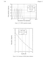
The basic test setup for roaming measurements comprises a DUT (a client, or two or more
APs, as mentioned above) together with a tester that serves as the counterpart device, as
shown in the following fi gure.
Different methods of inducing the roaming event exist in the industry today. One approach is
to use a pair of variable attenuators, adjusted so as to shut off one AP and enable the other AP;
the client will automatically roam from the fi rst to the second APs, at which point the roaming
metrics can be measured. The same setup is generally used for measurements on both clients
Ch05-H7986.indd 129Ch05-H7986.indd 129 6/28/07 10:16:27 AM6/28/07 10:16:27 AM
Chapter 5
130
and APs, the choice of the DUT being a matter of viewpoint rather than setup. As neither
APs nor clients are designed to be test equipment, the actual roaming measurements are made
by post-processing packet captures (“sniffer traces”) obtained from nearby wireless sniffers
during the roaming process.
Another approach, which is used for roaming measurements on APs and WLAN switches
when the clients are emulated and hence are under the control of the test system, is to
programmatically cause the emulated clients to roam, and make measurements during the
process. This avoids the repeatability and uncertainty issues caused by the use of off-the-shelf
clients (many of which have severe problems with stability and controllability), and allows
the roaming test to be performed rapidly and automatically. In addition, the need for wireless
sniffers or post-processing of sniffer traces is completely eliminated, and much higher-density
test setups are possible.
5.4.9 QoS Metrics
The IEEE 802.11e QoS standard is widely adopted for supporting VoIP traffi c over WLANs.
(Actually, the subset defi ned by the Wi-Fi® Alliance – Wi-Fi® Multimedia or WMM – is the
more common implementation, as the full IEEE 802.11e standard far exceeds what is typically
required for simple VoIP applications.)
SUT
Test AP In
Isolation
Chamber
(DUT or
Wireless
Counterpart)
Test AP In
Isolation
Chamber
(DUT or
Wireless
Counterpart)
Test Client In
Isolation
Chamber
(DUT or
Wireless
Counterpart)
Wireless
Sniffer
Ethernet
Switch
Security
Server
Typical Variable-Attenuator Roaming Test Setup Typical High-Density Roaming Test Setup
Variable
Attenuator
Variable
Attenuator
Splitter
Traffic
Generator
Traffic Generator
and Analyzer (TGA)
Host
Computer
with Test
Software
AP
AP AP
AP AP
AP
Security
Server
WLAN
Switch
Ethernet
Switch
WIRELESS
ACCESS
POINT
WIRELESS
ACCESS
POINT
Figure 5.6: Roaming Test Setup
Ch05-H7986.indd 130Ch05-H7986.indd 130 6/28/07 10:16:27 AM6/28/07 10:16:27 AM
Protocol Testing
131
QoS adds another dimension to performance testing of WLANs. In addition to standard
performance tests such as throughput and latency, QoS-specifi c metrics that are directly aimed
at quantifying how well the WLAN supports the needs of voice and video traffi c streams
become interesting.
Typical QoS performance metrics can be divided into two categories:
1. Low-level measurements that focus on how well an AP or client implements the 802.11e
protocol, especially the prioritization of traffi c.
2. Application-level measurements that try to determine the effi ciency of the QoS
implementation as a whole, and how it improves service quality for real-time traffi c.
Low-level QoS measurements are fairly limited, confi ning themselves to determining whether
traffi c streams in various priority classes are isolated from each other, and also whether QoS
mappings are preserved when transitioning between the wired and wireless media. These
are done by simply generating and mixing multiple traffi c streams assigned to different QoS
priority levels, and determining the level at which higher priority traffi c is affected by lower
priority traffi c. Note that QoS priority levels do not have much effect until some degree of
oversubscription or congestion occurs. Therefore, a typical test setup would ensure that the
aggregate offered load of all the traffi c streams presented to a WLAN device exceeded the
medium capacity, and then compare the loss, latency, and jitter of the high-priority streams
with that of the low-priority streams. If the high-priority streams remain unaffected even
though some portion of the low-priority streams are being dropped due to oversubscription,
then the QoS performance of the WLAN device is good.
Application-level QoS measurements are more interesting from an end-user point of view,
as end-users are rarely concerned about individual links but instead look at end-to-end
performance. Application-level QoS performance tests may be divided into two types:
capacity metrics and service assurance metrics.
Capacity metrics seek to determine the total capacity of a WLAN or device when carrying
delay or loss sensitive traffi c. For example, in a VoIP application, it is essential to determine
the maximum number of concurrent voice streams that can be carried before the QoS
guarantees break down; this aids the end-users (either enterprises or service providers) in
provisioning their network to deal with the maximum expected load. Capacity metrics are
usually measured in the presence of some fi xed amount of background traffi c. For example,
a capacity test could inject 1 Mb/s of best-efforts data traffi c into a WLAN switch, and then
measure the maximum number of voice calls that could be carried by that switch before the
voice quality dropped below a minimum threshold.
Service assurance metrics look at the ability of a WLAN or device to prevent delay and loss
sensitive traffi c from being affected by the bursts of data packets that are encountered in
Ch05-H7986.indd 131Ch05-H7986.indd 131 6/28/07 10:16:28 AM6/28/07 10:16:28 AM
Chapter 5
132
heavily loaded LANs. Once a voice call is established, maintaining call quality requires that
the network give priority to the VoIP traffi c carrying the call at the expense of best-efforts data
such as e-mail and fi le transfers. (A separate mechanism – referred to as call admission control
or CAC – is used to limit the number of voice calls to the capacity of the network.) A service
assurance measurement is therefore made by setting up a pre-defi ned number of voice calls,
and then gradually increasing the amount of best-efforts data traffi c until the voice quality
drops below a minimum threshold.
Determining the application-level quality of a delay or loss sensitive traffi c stream is an art in
itself. For voice streams, well-defi ned metrics exist, such as the R-factor (also called the R-value)
defi ned in ITU-T G.107; the R-factor attempts to measure call quality in terms of the predicted
satisfaction level of humans listening to the voice call. More accurate, but also more complex,
perceptual speech quality metrics (PESQ and PSQM) have also been defi ned for quantitative
measurements of VoIP traffi c. Video stream quality measurement is, however, still in its infancy.
To date, video quality metrics have been subjective (i.e., relying on human viewers to rate the
quality of video streams) rather than objective. Organizations such as the Video Quality Experts
Group (VQEG) and even some companies such as Intel and IneoQuest are attempting to defi ne
objective video quality metrics, but this is a research topic as of the writing of this book.
5.4.10 An Alternative Classifi cation
The same performance metrics can also be classifi ed into two categories: data-plane metrics
and control-plane metrics. This classifi cation becomes useful when trying to understand which
portion of a DUT is affected by a specifi c metric, and, by extension, where to start looking if a
test produces a poor result.
Data-plane metrics pertain to the performance of the basic frame processing and forwarding
functions within the DUT (i.e., what is commonly referred to as the DUT datapath). For
example, a throughput test directly measures the ability of a DUT to receive, classify, switch,
buffer, and retransmit frames; low results on a throughput test usually indicate some issue
in one of these areas, such as packets being lost due to a poorly selected buffer management
algorithm.
Control-plane metrics apply to the state and context management functions within the DUT,
such as those related to client state update when handling mobile clients. An example of
a control-plane metric is roaming delay. Roaming is usually quite stressful on the control
functions within the DUT, because the client context at the original location of the client must
be torn down and new context established at the new location, all within as short a time as
possible. The impact of the DUT forwarding path is at best second order; a DUT with poor
throughput may still be able to offer superior roaming performance, provided that careful
attention has been paid to the design of the control software that maintains client context and
manages security.
Ch05-H7986.indd 132Ch05-H7986.indd 132 6/28/07 10:16:28 AM6/28/07 10:16:28 AM
Protocol Testing
133
The following table summarizes a non-exhaustive set of data-plane and control-plane metrics:
Data-Plane Metrics Control-Plane Metrics
Throughput Association rate
Forwarding rate Reassociation time
Frame loss rate Association database capacity
Latency Roaming delay
Jitter Dropped connections
Burst capacity Reset recovery
Power-save buffer capacity
QoS capacity
5.5 Standardized Benchmark Testing
There is probably no area of protocol testing that rouses as much interest – and controversy! –
as standardized benchmark measurements. Benchmarking brings together QA engineers,
marketing people, magazine publishers and even end-users, all of whom are attempting to
answer one question: which equipment is better? It is in fact the one time when the activities
of the QA department can actually make it to the top of the CEO’s priority list.
5.5.1 Lies, Damned Lies, and Benchmarks
Benchmark testing is not merely a LAN or even networking phenomenon; standardized
benchmark tests are used throughout the computer industry. (For example, the Linpack
benchmark originated by Jack Dongarra measures the computational performance of
supercomputers.) The ostensible purpose of a benchmark test is to quantitatively rank
equipment, usually from different vendors, based on some objective quality metrics.
Unfortunately benchmarks, like statistics, can be structured and twisted to support any
arbitrary point of view, particularly if the metric is poorly defi ned or the test is poorly executed
(see Section 5.4.2 on performance testing).
A good benchmark test needs to bear some correlation to a non-trivial part of the end-user’s
experience. There is little point in testing some aspect of a networking device that may be
interesting to an engineer but does not substantially affect the ultimate end-user. The nature of
benchmark testing in fact indicates the maturity of an industry; initially, benchmark numbers
tend to focus on whizz-bang capabilities that are of interest to technophiles, but as the industry
matures the focus shifts to metrics that the end-user can actually utilize in order to better
design and deploy the equipment.
Another hallmark of a good benchmark test is simplicity. It should be easy to explain to an
end-user why he or she should be interested in the results of the benchmark. Not only should
Ch05-H7986.indd 133Ch05-H7986.indd 133 6/28/07 10:16:28 AM6/28/07 10:16:28 AM
Chapter 5
134
the benchmark itself be simple, but it should be intuitively obvious (when presented with two
sets of test results) which results are better and why. The more complicated and contrived a
benchmark, the less likely it is that it will have much correlation to end-user experience.
5.5.2 Comparative Testing
Virtually all benchmarks are relative in nature, even though their test results may yield
absolute performance numbers. That is, benchmark test results on a given piece of equipment
have little value (i.e., as benchmarks) unless they can be compared with the results of similar
tests performed on other equipments of the same type. Benchmark testing is thus highly
comparative in nature. In fact, most benchmark testing campaigns are performed with
equipment from different vendors being tested at the same time, or at least in the same test
campaign. The results are usually presented side-by-side for easy comparison.
This highlights one aspect of benchmarking, namely, the competitive nature of benchmark
testing. Understandably, marketing departments usually spend a good deal of time attempting
to make benchmark test results of their company’s equipment look better than that of their
competitors’. It is therefore essential to ensure that benchmark tests are performed the same
way on all equipments; to facilitate this, a well-designed benchmark test will specify virtually
all aspects of the test setup, the test conditions and the equipment confi guration parameters,
down to the MAC and IP addresses to be used and the time allowed between test trials.
Comparative benchmarking has become such an institution in the networking industry
that there are even institutions (such as the Tolly Group, and Network Test) that have been
established with the purpose of performing independent comparative tests on different
vendors’ equipment.
5.5.3 Typical Benchmarked Metrics
Benchmark tests are almost without exception a subset of the normal performance tests that
are typically carried out by manufacturer or user QA labs on WLAN equipment or systems.
The same metrics are used, and similar test procedures are followed. The primary difference
is that the level of rigor, documentation, and scrutiny is much higher – QA performance tests
are not usually carried out with several marketing departments breathing down the neck of the
person conducting them!
The most common benchmark tests for WLAN equipment are the usual suspects:
• throughput,
• forwarding rate and packet loss,
• latency,
• scalability in terms of number of clients and APs,
Ch05-H7986.indd 134Ch05-H7986.indd 134 6/28/07 10:16:28 AM6/28/07 10:16:28 AM
Protocol Testing
135
• roaming measurements,
• QoS measurements.
Functional and conformance tests should obviously not be made the subject of benchmark
testing. Not only are they frequently specifi c to the equipment, they are of little interest to an
end-user.
5.5.4 Dos and Don’ts of Benchmark Testing
A properly conducted benchmark test campaign can yield results that are both useful and
interesting to the end-user community. However, there are plenty of pitfalls along the way to
trip up the unwary or the careless. Some of them are:
• Testing a modifi ed DUT. Benchmark campaigns are usually accompanied by several
engineers and marketing people from the companies selling the equipment, who are
usually all too anxious to “tweak” the DUT in order to get better test results. In many
cases these “tweaks” can render the DUT useless in a production network, though
they produce excellent results when running benchmark tests. Good benchmark
testers resist such pressures, and insist instead that the DUT should be set up exactly
according to the instructions provided to the end-user.
• Selecting a proper benchmark traffi c load. Random mixes of traffi c lead to wildly
varying and often unrepeatable results. Also, failure to control all aspects of the test
traffi c can produce quite a bit of variation, independent of DUT characteristics. The
traffi c injected into the DUT needs to be well-controlled and well-defi ned; otherwise the
benchmark campaign can degenerate into a test of the patience of the person running the
benchmarks.
• Recording all results. Not all equipment can score equally well on a benchmark test.
In fact, if they did so, then the benchmark test would be quite uninteresting. It is not
unusual for the marketing or engineering departments of the low-scoring equipment
to violently challenge the quality of the test equipment, the veracity of the tester, the
nature of the test traffi c – everything, in fact, except their own LAN gear. (In some
cases there may even be legal liabilities.) To defend against this, it is essential to save
everything pertaining to each and every benchmark test until the test has passed out of
the public eye.
• Misbehaving DUTs. A non-compliant DUT can make the results of performance
tests very puzzling indeed. For example, a DUT that does not implement the
802.11-mandated protocol timers and inter-frame spacing can appear to have higher
than possible throughput numbers. If possible, a conformance test should be conducted
on the DUT before embarking on an extensive benchmark test campaign to smoke out
such devices, or at least understand what could be causing strange test results.
Ch05-H7986.indd 135Ch05-H7986.indd 135 6/28/07 10:16:29 AM6/28/07 10:16:29 AM
This page intentionally left blank
137
Application-Level Measurements
Application-level measurements resonate well with end-users; they provide a sense that there
is some correlation to the ultimate end-user experience, rather than being merely some abstract
property of the infrastructure devices. In some situations, such as in the case of the WLAN
industry of 2006 or before, the lack of more advanced test tools drives the manufacturers and
vendors themselves to make application-level measurements, because such measurements can
be made with little more than the actual applications themselves, or a simulacrum thereof. As
a consequence, much of the WLAN industry today still relies on application-level metrics and
measurements to indirectly determine the capabilities of the underlying WLAN hardware and
software. This chapter covers some of the key application-level tests and setups used in current
practice. The focus is on system-level testing for enterprise and multimedia applications.
6.1 System-level Measurements
Application-level measurements are also referred to as system-level measurements, because
they attempt to characterize the performance of a system as a whole, rather than any piece or
subset of it. Much more than simply wireless clients and access points (APs) are involved
by necessity in transporting traffi c from its source to its sink, particularly when dealing with
real-time traffi c such as voice and video. A packet voice circuit usually comprises, from
start to fi nish: a microphone, an audio encoder (codec), a packetizer, a wireless client, an AP,
a wired network infrastructure (switches and routers), a call server or Voice over IP (VoIP)
gateway, another AP, another wireless client, a depacketizer, an audio decoder (another
codec), and a speaker or earphone. Each element of the chain has an impact on the perceived
quality of the delivered audio. Thus obtaining a true picture of the complete packet voice
system necessitates end-to-end measurements, which are obviously best done at the
application level.
6.1.1 Your Mileage May Vary
Application-level measurements are of immediate interest to both end-users and enterprise
IT people because they appear to directly quantify the anticipated user experience. Making
measurements of the underlying parameters of a local area network (LAN) connection such
as latency and packet loss is all well and good, but nothing can match the immediacy of a
direct measurement of voice quality (preferably using actual audio samples, or even human
CHAPTER 6
Ch06-H7986.indd 137Ch06-H7986.indd 137 6/28/07 1:14:43 PM6/28/07 1:14:43 PM
Chapter 6
138
listeners). Measurements at the application layer are thus appealing to virtually all network
managers and users, even technically sophisticated ones.
There is one substantial caveat, though: being end-to-end measurements, application-level
metrics are affected by more than just the wireless equipment that carries the traffi c. For
instance, while voice quality is certainly impacted by loss and jitter in the wireless LAN, it
is just as much a function of the type of codec used, the quality of the call server or gateway,
and in fact the fi rmware (OS and drivers) running on the handsets. This necessitates a certain
amount of care when using application-layer metrics to quantify the performance of WLAN
equipment; poor test results do not necessarily imply that the WLAN devices are at fault,
unless all other elements along the entire end-to-end path have been considered and ruled out.
A second, less well-understood problem with application-level measurements is repeatability.
Almost by defi nition, the application layer in any protocol suite is complex and somewhat
unpredictable. It is extremely diffi cult to set up the same initial conditions twice when
running a real application, because the state of the application is determined by a myriad of
software and hardware interactions as well as an operating system. Most application-level
measurements rely on running many iterations of a particular test over long periods of time
to average out the uncertainties in the initial state of the application layer and the random
interactions with the rest of the system. In spite of this, application-layer metrics usually have
to settle for a higher level of uncertainty and a lower degree of repeatability than any other
kind of measurement.
Thus, one should not take small differences in measured results too seriously when conducting
application-layer testing. By the same token, one should not expect more than a fi rst-order
approximation to the actual performance of the WLAN when installed in the live network.
6.1.2 Enterprise WLAN
Before plunging into how application-level measurements are performed, it is worth taking
another look at the architecture of a WLAN with different types of end-user devices. Figure
6.1 depicts a simplifi ed view of a typical enterprise WLAN setup.
A modern enterprise WLAN integrates a wide variety of equipment and technologies. The
actual mix is dependent on the nature of the enterprise as well as the choices made by users
and administrators; the fi gure only shows what is possible:
• The most ubiquitous WLAN clients are, of course, laptops. The most common data
applications on these clients are e-mail, fi le service, and Web browsing, but other
applications such as VoIP (e.g., Skype), conferencing, and video are also prevalent.
Personal Digital Appliances (PDAs) are basically cut-down versions of laptops.
• VoIP handsets (basically, phones using WLAN interfaces) are also present, though less
prevalent at the moment.
Ch06-H7986.indd 138Ch06-H7986.indd 138 6/28/07 1:14:43 PM6/28/07 1:14:43 PM
Application-Level Measurements
139
• More esoteric devices such as bar-code readers and radio-frequency identifi cation
(RFID) tags are coming into use for asset tracking and inventory purposes.
• The above WLAN clients are provided access to the wired infrastructure by means of
APs. There is usually only one wireless hop between a client and the nearest wired
node; occasionally there may be more, as in the case of wireless bridges or wireless
mesh networks.
• The AP connects directly to an Ethernet port on a switch; the latter is increasingly
becoming a “wireless-aware” device that is capable of fi nding and managing APs
directly.
• Various pieces of wired Ethernet gear such as switches and routers make up the
rest of the wired LAN infrastructure. Most enterprises also have interfaces to an
Internet Service Provider (ISP) or WAN transport links to remote sites, which require
additional Ethernet or non-Ethernet equipment to support.
• Connected to the wired LAN infrastructure are several different types of servers
(servers are almost never connected using wireless links – there is little use in having a
server that could be picked up and moved away without warning).
All of the traffi c to and from the WLAN clients invariably terminates on one or the other
servers; it is extremely unusual to fi nd packets that originate on a WLAN client and terminate
Barcode Readers and RFID Tags in
Warehouse
Phones (Handsets) and PDAs in Mobile
Areas
Laptops in Workspaces
Data Center
Switches, Routers, Servers
Switched Ethernet
LAN Infrastructure
AP AP AP AP AP AP AP AP AP AP
APAP APAPAP
RADIUS
Authentication
Servers
DHCP
Servers
WLAN
Switches
APs mounted on walls and ceilings
Routers
Wiring
Closet
Switches
Wiring
Closet
Switches
Wiring
Closet
Switches
Data
Center
Switches
To Branch
Offices
Internet
Access
PBX
VoIP
Servers
Figure 6.1: Enterprise WLAN Topology
Ch06-H7986.indd 139Ch06-H7986.indd 139 6/28/07 1:14:44 PM6/28/07 1:14:44 PM
Chapter 6
140
on another WLAN client, without a server of some kind in the middle. Even voice packets must
traverse a VoIP server before reaching their destination. Typical examples of servers are fi le
servers, e-mail servers, Web servers, VoIP call servers (or PBX gateways), video servers, and
so on. Most network applications are written specifi cally with a client-server model in mind, so
that each client application usually corresponds to a server somewhere on the LAN or Internet.
6.1.3 Enterprise vs. Consumer
While the equipment used in consumer situations is conceptually similar to that in
enterprises – after all, a WLAN reduced to its most basic form consists of an AP, a client
and a wired infrastructure – the application traffi c encountered is completely different.
Further, enterprise WLANs tend to be fairly homogeneous, but consumer networks are often
aggressively heterogeneous.
Enterprise applications have less emphasis on real-time requirements and much more need for
high bandwidth, scalability, robustness, and security. By contrast, consumer applications of
WLANs stress real-time functions to a much greater degree. Multimedia traffi c, multiplayer
games (another intensively real-time situation) and VoIP are found to a much higher degree in
consumer settings, while fi le servers are usually not. In fact, the goal towards which consumer
equipment vendors are working is a home network that enables seamless integration of home
computers, entertainment devices and the Internet (see Figure 6.2).
Internet
Access
Satellite
TV
APAP
Video
Security
HD Monitor
Portable
Video
Player
Home Entertainment
System
HD Video
Camera
Set-Top Box
and Recorder
Music System
Media Server
Home Computer
Figure 6.2: The Consumer WLAN Utopia
Ch06-H7986.indd 140Ch06-H7986.indd 140 6/28/07 1:14:44 PM6/28/07 1:14:44 PM
Application-Level Measurements
141
Traffi c and test procedures that quantify the end-user experience with consumer equipment
are thus quite different from those for enterprise equipment. Scalability is obviously not a
concern at all – it is hard to imagine a home network with hundreds of clients – and a greater
degree of uncertainty in the measurements is acceptable. Instead, coverage area, resistance to
interference, support for real-time applications, and interoperability are the prime foci.
6.1.4 Vertical Applications
Wireless LANs are somewhat unique in the networking industry in terms of the rate at which
they have penetrated specialized “vertical” applications. An example of a vertical application
is warehousing. The use of WLANs in warehouses is common; by contrast, wired LANs have
had little or no impact here. WLANs are routinely used to provide the infrastructure for bar-
code readers, RFID devices, asset location and tracking systems, and automated inventory
management. Other examples of vertical applications for WLANs are hospitals (everything
from miniature VoIP phones to patient monitors), factories, aircraft maintenance hangars, and
retail stores.
Each vertical application offers unique challenges in testing, not the least of which is generating
the traffi c required for driving the wireless infrastructure. For example, a WLAN-based RFID
system may be required to track thousands of tags, each representing a “client”; however,
testing the system by actually using such tags (and then moving them about from place to
place) is clearly very expensive and not very practical. At the same time, the traffi c encountered
in an RFID system does not resemble that in common enterprise or consumer scenarios, so
using test equipment and procedures used for the latter is not a very realistic method of testing.
Testing WLANs in vertical applications continues to be a fairly challenging problem.
6.1.5 Usage Cases
Maintaining the end-user orientation of application-level measurements, we can categorize the
metrics being measured into usage cases. A usage case is an attempt to narrow the focus of a
measurement scenario; each usage case represents a typical end-user activity, and is associated
with a set of metrics that quantify the end-user experience. For example, all metrics related
to voice calls can be grouped into a “VoIP usage case”, while measurements pertaining to fi le
transfer could be categorized in a “data usage case”.
The IEEE 802.11.2 draft standard (see Appendix A) has conveniently specifi ed three usage
cases that cover virtually all end-user applications currently known to exist on a WLAN:
• A latency-sensitive usage case that encompasses applications that are highly sensitive
to latency, jitter and packet loss, but much less demanding of bandwidth. The most
obvious example of an application that falls into this usage case is packet voice, but
network conferencing is also covered.
Ch06-H7986.indd 141Ch06-H7986.indd 141 6/28/07 1:14:45 PM6/28/07 1:14:45 PM