cisco press router security strategies phần 3 pps
Bạn đang xem bản rút gọn của tài liệu. Xem và tải ngay bản đầy đủ của tài liệu tại đây (6.36 MB, 67 trang )
Further Reading 113
Further Reading
Behringer, M., and M. Morrow. MPLS VPN Security. Cisco Press, 2005. ISBN:
1-58705-183-4.
Bellovin, S. “A Look Back at ‘Security Problems within the TCP/IP Protocol.’”
20th Annual Computer Security Applications Conference. (Dec. 2004): 229-249.
/>Bellovin, S. “Routing Threats.” Columbia University, April 10, 2006.
http://72.14.209.104/search?q=cache:cLj6O5bgUNQJ:
www.cs.columbia.edu/~smb/talks/routesec-arin.ps+routing+
security+attacks&hl=en&gl=us&ct=clnk&cd=10.
Bellovin, S. “Towards a TCP Security Option.” draft-bellovin-tcpsec-00. IETF,
Oct. 15, 2006.
Clark, D. “Vulnerability’s of IPsec: A Discussion of Possible Weaknesses in IPsec
Implementation and Protocols.” SANS Institute, March 14, 2002.
/>760.php?portal=a207e10e552a50dba6f2fd8079afd772.
Dubrawsky, I. “Safe Layer 2 Security In-depth – Version 2.” Cisco white paper.
March 2004. />Fang, L. Security Framework for Provider-Provisioned Virtual Private Networks
(PPVPNs). RFC 4111. IETF, July 2005. />Gont, F. “Increasing the Payload of ICMP Error Messages.” draft-gont-icmp-payload-
00. IETF, Aug. 2, 2004. />Gont, F. “ICMP Attacks Against TCP.” draft-ietf-tcpm-icmp-attacks-01. IETF,
Oct. 23, 2006. />Greene, B. R., and P. Smith. ISP Essentials. Cisco Press, 2002. ISBN: 1-58705-041-2.
Halpern, J., S. Convery, and R. Saville. “SAFE: VPN IPsec Virtual Private Networks
in Depth.” Cisco white paper. March 2004.
/>Householder, A., and B. King. “Securing an Internet Name Server.” CERT/CC,
Aug. 2002. />Lam, K., D. LeBlanc, and B. Smith. Assessing Network Security. Microsoft Press,
2004. ISBN: 0-73562-033-4.
Longstaff, T. A., J. T. Ellis, S. V. Hernan, H. F. Lipson, R. D. McMillan, L. H. Pesante,
and D. Simmel. “Security of the Internet.” CERT/CC, Aug. 2002. />encyc_article/tocencyc.html.
114 Chapter 2: Threat Models for IP Networks
May, C., J. Hammerstein, J. Mattson, and K. Rush. “Defense in Depth: Foundations
for Secure and Resilient IT Enterprises.” CERT/CC, Sept. 2006. />archive/pdf/Defense_in_Depth092106.pdf.
Ramaiah, A., R. Stewart, and M. Dalal. “Improving TCP’s Robustness to Blind
In-Window Attacks.” draft-ietf-tcpm-tcpsecure-06. IETF, Nov. 7, 2006.
/>Retana, A. “Routing Protocols Security.” Cisco Systems. Cisco Networkers 2005.
Las Vegas. June 19, 2005.
Singh, B., and S. S. Sofat. “Future of Internet Security – IPSec.” SecurityDocs.com,
Jan. 26, 2005. />Tanase, M. “IP Spoofing: An Introduction.” SecurityFocus, March 11, 2003.
/>Touch, J. “Defending TCP Against Spoofing Attacks.” draft-ietf-tcpm-tcp-antispoof-
04. IETF, May 15, 2006. />Tulloch, M. “DHCP Server Security (Part 1).” WindowSecurity.com, Oct. 27, 2006.
/>Tulloch, M. “DHCP Server Security (Part 2).” WindowSecurity.com. Oct. 27, 2006.
/>Watson, P. A. “Slipping in the Window: TCP Reset Attacks.” OSVDB, Dec. 25, 2003.
/>White, R., A. Retana, and D. Slice. Optimal Routing Design. Cisco Press, 2005.
ISBN: 1-58705-187-7.
Willman, M. “NTP Security.” GIAG, Aug. 2002. />certified_professionals/practicals/gsec/2115.php.
“ICMP Parameters.” IANA. />“IP Parameters.” IANA. />“Managed VPN – Comparison of MPLS, IPSec, and SSL Architectures.” Cisco white
paper. />networking_solutions_white_paper0900aecd801b1b0f.shtml.
“Network Security Policy: Best Practices White Paper.” (Doc. ID: 13601.) Cisco
white paper. />Further Reading 115
“Securing IP Multicast Services in Triple-Play and Mobile Networks.” Cisco white
paper. />products_white_paper0900aecd80557fd4.shtml.
“VLAN Security White Paper.” Cisco white paper.
/>products_white_paper09186a008013159f.shtml.
“VPN Architectures—Comparing MPLS and IPSec.” Cisco white paper.
/>networking_solutions_white_paper09186a008009d67f.shtml.
In this chapter, you will learn about the following:
• The principles of defense in depth and breadth, and how these principles apply to IP
network traffic plane security
• IP network element interface concepts and how these apply to IP network traffic plane
security
• IP network edge and core security concepts, how these differ for enterprise and SP
environments, and how these apply to IP network traffic plane security
C HAPTER
3
IP Network Traffic Plane
Security Concepts
IP traffic plane concepts provide the mechanisms from which comprehensive IP network
security strategies can be implemented. Before discussing detailed security techniques and
implementations for each of the four IP network traffic planes, which occur in Chapters 4
through 7, it is useful to look at how cohesive, integrated security policies based on IP
network traffic plane concepts can be developed. The first important concept is that of
defense in depth and breadth, and specifically, how the principles of defense in depth and
breadth apply to IP traffic plane security. The next concept involves the special relationships
between the network edge and core and the ability to classify packets and enforce security
policies.
Principles of Defense in Depth and Breadth
The concepts of “defense in depth” or, more appropriately, “defense in depth and breadth”
are often used by network security professionals to operationalize “layered defense”
techniques for protecting network assets. Defense in depth became popularized in the late
1990s under research conducted by military and intelligence organizations as well as by
various universities. Knowing that the concepts of defense in depth were formalized in a
military environment aids in the understanding of how these techniques arose. Military
strategies are typically defined to counter specific adversaries, weapons, and objectives. In
the networking world, these concepts were adopted for cyber adversaries under certain
attack scenarios and led to the development of various defensive strategies.
Initially, defense in depth applied multiple layers of defense technologies—including
network-based techniques such as access lists and encryption, security appliances such as
firewalls and intrusion detection systems (IDS), and software programs such as antivirus,
host-based intrusion detection, and personal firewalls—throughout an enterprise network
to protect sensitive information and business-critical resources. In theory, greater security
is provided by forcing the attacker to penetrate these multiple layers, devices, or software
elements, often of different implementations (for example, a hardware-based firewall and
then a software-based personal firewall), such that if one layer is compromised, secondary
layers are available to mitigate the attack. This approach is predicated on the expectation
that adding multiple layers increases the difficulty and skills required to successfully attack
the target. Defense in depth was later expanded to encompass more than hardware and
software systems by incorporating personnel and operational requirements as well.
118 Chapter 3: IP Network Traffic Plane Security Concepts
Defense in depth is often illustrated through the use of analogies taken from the physical
world and then (oftentimes inappropriately) extended to the cyber world. One of the most
popular examples describes a high-security facility with fences (perhaps multiple,
separated by some distance), locked doors, guards inside the doors, and video surveillance
cameras. Although this seems appealing as an analogy, these physical concepts do not
necessarily translate well in the cyber world. Most obvious of course is the physical aspect
of the analogy. IP reachability and connectivity to the Internet means that anyone with a
networked personal computer (PC) located anywhere in the world can target any other
Internet-connected device. Conversely, in the real world, you must be physically proximate
to the target to attack it. Less obvious, perhaps, is the “asymmetry” afforded attackers in the
cyber world. A single PC or a single person who has organized a “zombie army” of
compromised PCs (that is, a roBOT NETwork or botnet as it is commonly referred to) may
cause great damage with little or no active involvement of others or expenditures of funds.
In the real world, a single person is limited in destructive capability and generally requires
the active cooperation of others to launch a large-scale attack.
Perhaps least translatable is the notion of spectrum. In the physical world, visible, thermal,
acoustic, and seismic sensors, all guarding the same valuable object, provide the ability to
measure parameters in different spectra, which improves the protection capabilities over a
single spectrum sensor. In the networking world, most security revolves around scrutinizing
and controlling IP packets. It is often difficult to find a measurable analog to spectrum in
the cyber world. Monitoring parameters such as CPU and memory utilization of devices
and enforcing application behaviors may be useful for detecting (and preventing) some
types of attack. Finally, it is not often that a protection mechanism in the physical world
actually becomes a liability to defense, but this happens often in the cyber world,
specifically with respect to DoS attacks. (This concept is discussed in more detail in the
“What Are Defensive Layers” section.)
Understanding Defense in Depth and Breadth Concepts
When properly understood and implemented, defense in depth and breadth techniques are
very useful for constructing and deploying network security policies from an IP network
traffic plane perspective. This requires a clear understanding of the most important defense
in depth and breadth concepts. This can be accomplished by addressing the following
questions in the context of IP network traffic planes:
• What needs to be protected?
• What are defensive layers?
• What is the operational envelope of the network?
• What is your organization’s operational model?
Let’s look at these important questions separately.
Principles of Defense in Depth and Breadth 119
What Needs to Be Protected?
Determining what needs to be protected is not necessarily as straightforward as it seems.
Some organizations may need to protect assets such as trade (or military) secrets and other
intellectual property. Others need to protect e-commerce site access (which could be
bandwidth or server resources or both), credit card or customer databases, and health care
records. Service providers (SP), on the other hand, often have very different needs because
their value is in the network and services they provide. Ensuring network and service
availability is paramount for SPs, so they need to protect network assets, including IP routers,
switches, VoIP gateways, security appliances, and other network assets such as DNS servers,
Internet peering links, and billing servers.
As is most often the case, you will need to expend some effort to deploy security measures,
and when they are deployed, you will incur a level of administrative overhead and operational
inconvenience, and may also find that there is an impact to network performance. Not
everything can be protected equally, and you will need to make trade-offs that fully consider
the risk and the cost of applying the security measures needed to mitigate the risk to
acceptable levels.
In addition, orthogonal linkages between high-value assets and peripheral or relatively
obscure services or devices may expose vulnerabilities that enable indirect attacks. These
indirect attacks can cause substantially the same kind of impacts against a target that has only
been protected against direct attack. DNS is a classic example from the e-commerce world.
You may expend significant resources and money protecting your web servers but give little
consideration to the DNS servers, leaving them vulnerable to any number of malicious
attacks. Without DNS, the availability of the web site that itself was the primary focus of
your security efforts will be severely impacted. ARP tables and routing tables are good
examples of control plane elements that are often attacked not for the direct impact but
for the indirect, collateral damage effects that these attacks cause on surrounding systems.
In summary, the key concepts when determining what needs to be protected are:
• Understand where the value is in the network and how this translates to the primary
services and devices that must be protected.
• Understand the interrelationships between various network services and devices and
how each may be leveraged to indirectly target the high-value resource.
What Are Defensive Layers?
Defense in depth and breadth describes the use of multiple layers, which are often
implemented as distinct devices such as routers, firewalls, and intrusion protection systems
(IPS), or as software such as antivirus or personal firewall applications. In most cases, this
granularity is too coarse, because within each of these devices or applications themselves,
multiple operations may be considered as providing some layer of protection. When
considering a router, for example, packets ingressing an interface are affected by a number
120 Chapter 3: IP Network Traffic Plane Security Concepts
of hard-coded and configurable processes both before and after the routing function occurs.
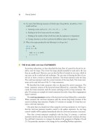
Figure 3-1 illustrates the typical packet processing “order of operation” that Cisco IOS
routers employ. (Some variations in feature ordering may occur in specific router platforms
and IOS software releases.)
Figure 3-1 Cisco IOS Feature Order of Operations
Each of these features, when implemented, must be considered as a layer because each may
potentially impact the forwarding of the packet (permit, deny, rate-limit, mark/color), and in
fact each operation may impact the performance of the router (CPU and memory, throughput,
and so on). It is also important to note that each upstream layer may also have an impact on
the effectiveness and performance of other downstream layers in the overall system.
Layers are selected to protect against specific attack vectors. By considering each feature
as an individual layer rather than considering the entire device as a layer, you can clearly
distinguish the purpose that each layer fulfils. This enables you to develop a security
architecture that addresses both depth and breadth aspects, as required. But what are these
concepts of depth and breadth? Depth and breadth can be described as follows:
• Depth—When considering a single service, if one layer is added to protect against a
particular attack vector, and then a second layer is added to protect against the same
attack vector, the second layer provides depth against that specific attack vector.
Depth is generally used to provide redundant layers such that if one is compromised,
the target remains protected by the secondary layers. An example of depth principles
Egress
Routing
Ingress
Egress Features
1. WCCP Redirect
2. NAT Inside-to-Outside
3. Network Based Application Recognition (NBAR)
4. BGP Policy Accounting
5. Output QoS Classification
6. Output ACL check
7. Output Flexible Packet Matching (FPM)
8. DoS Tracker
9. Output Stateful Packet Inspection (IOS FW)
10. TCP Intercept
11. Output QoS Marking
12. Output Policing (CAR)
13. Output MAC/Precedence Accounting
14. IPsec Encryption
15. Egress NetFlow
16. Egress Flexible NetFlow
17. Egress RITE
18. Output Queuing (CBWFQ, LLQ, WRED)
1. IP Traffic Export (RITE)
2. QoS Policy Propagation through BGP (QPPB)
3. Ingress Flexible NetFlow
4. Network Based Application Recognition (NBAR)
5. Input QoS Classification
6. Ingress NetFlow
7. IOS IPS Inspection
8. Input Stateful Packet Inspection (IOS FW)
9. Input ACL
10. Input Flexible Packet Matching (FPM)
11. IPsec Decryption (if encrypted)
12. Unicast RPF check
13. Input QoS Marking
14. Input Policing (CAR)
15. Input MAC/Precedence Accounting
16. NAT Outside-to-Inside
17. Policy Routing
Ingress Features
Principles of Defense in Depth and Breadth 121
would be using a router-based ACL to permit traffic only to TCP port 80 of a web
server, and then deploying a host-based ACL on the web server that also restricts
inbound traffic to only TCP port 80.
• Breadth—When considering a single service, if one layer is added to protect against one
specific attack vector that could compromise the service, and then a second layer is
added to protect against a completely different attack vector against that same service,
these layers are considered as providing breadth for attacks against that service. For
example, consider the BGP service. One layer might configure MD5 authentication on
each BGP peer to mitigate the risk of router advertisement spoofing. Adding an edge
ACL to permit only valid BGP peers from communicating protects the BGP service
from the separate and distinct attack vector by preventing non-BGP peers from reaching
the service. (For more information on ACLs and MD5 authentication, refer to Chapter 4,
“Data Plane Security,” and Chapter 5, “Control Plane Security,” respectively.)
When combined, defense in depth and breadth aim to mitigate as many potential attack
vectors as practical, while at the same time providing backup protection if any one
defensive layer is compromised.
A single layer may also provide protection against multiple attack vectors. When viewed
from an IP network traffic plane perspective, a single layer may be effective in protecting
(or have an impact on) multiple traffic planes. In IOS, for example, features such as interface
ACLs and Unicast Reverse Path Forwarding (uRPF) affect every packet ingressing an
interface and therefore have an impact on all four traffic planes. Other features such as Control
Plane Policing (CoPP) or Receive ACLs (rACL) apply to punted traffic only and therefore
affect only control plane and management plane traffic. (For more information on ACLs
and uRPF, refer to Chapter 4. For more information on CoPP and rACL, refer to Chapter 5.)
It is critical to note that simply adding more layers is not always beneficial. Each layer,
although intended to provide protection against a specific attack vector, may also enable
additional attack vectors that previously did not exist without that layer having been
deployed. That is, adding a protection layer against an attack vector in one domain may also
create a new attack vector that may be exploitable in another domain. Stateful security
devices such as firewalls and IPS systems often have this effect when improperly sized for
different attack conditions, potentially enabling a DoS attack vector where one previously
did not exist. The entire system must be considered when developing a layered strategy.
In addition, adding one type of security layer may negate the effectiveness of another type
of security layer. For example, encryption is often added to provide confidentiality and
integrity protection for data traversing unsecured networks. However, this same encryption
layer negates the effectiveness (against certain attack vectors) of intrusion detection and
protection systems (IDS/IPS) by making payload inspection impossible.
In summary, the key concepts regarding defensive layers are as follows:
• Understand which layers are available per device.
• Understand what attack vectors each layer is effective against.
122 Chapter 3: IP Network Traffic Plane Security Concepts
• Understand how adding layers impacts each IP network traffic plane.
• Understand how layers can be combined to provide depth and breadth as a system.
• Understand the implications and interactions each layer has on other layers and the
system as a whole.
Chapters 4 through 7 provide details on how different techniques may provide distinct
layers of protection for each of the IP traffic planes.
What Is the Operational Envelope of the Network?
All network devices have certain performance characteristics that can be measured in terms
of parameters such as bits per second of throughput, packets per second of forwarding,
transactions per second of application processing, and so on as might be relevant to a
particular device. For most network devices, performance characteristics are impacted not
only by the type and number of features that are enabled, but also by the type and quantity
of network traffic being processed. These performance characteristics then define the
operational envelope of the device. The combination of devices within a network topology
in aggregate implies that the overall system also has an operational envelope. Whereas it is
necessary to understand the operational envelope for your devices and the overall network
under ideal or normal operating conditions, knowing these operational envelopes is
especially crucial under attack conditions.
In Chapter 1, “Internet Protocol Operations Fundamentals,” you learned that the forwarding
functions of a router may be implemented in hardware (fast path) or software (slow path).
This is also true of the security features. All devices, security and otherwise, have
performance limits. Each feature enabled on a device may potentially have some impact on
its performance. Depending on the feature and its implementation method (hardware or
software), this impact may be negligible or significant to the operational envelop of the
device. This is one reason why the previous section stressed that enabling a feature (layer)
for protection may actually produce adverse effects or enable a new attack surface that
makes the overall system more susceptible to attack. In addition, enabling a particular
security feature on one type of device (or router platform) may have a far different impact
than enabling the same type of feature on a different type of device (or router platform).
Oftentimes, network security architectures are developed where certain features are
enabled full-time to create a security baseline, and then additional features are enabled
dynamically, under attack conditions. For example, an SP may enable on-the-fly (in
reaction to an attack) an ACL on the interface serving the customer under attack. In this
scenario, two conditions are occurring simultaneously, both of which may have an impact
on the operational envelop of the device or network. First, an attack condition is underway.
Thus, the packet rate, packet size, or packet characteristics (for example fragments,
IP header options, and so on) may be much different from what they are under normal
conditions. Second, the addition of the ACL may change the device performance. This is
why it is critical to understand the operational envelop of your devices and networks when
specific features are enabled, and under normal and attack conditions. At some point,
Principles of Defense in Depth and Breadth 123
under certain conditions, every device can reach some resource exhaustion state. It is
critical to understand how each device behaves when certain features are enabled under
adverse conditions. This is why it is critical to understand the operational envelop of your
devices and networks when specific features are enabled, and under both normal and
attack conditions. For DoS attacks in particular, the most destructive approach possible is
often used.
In summary, the key concepts in determining the operational envelope of the network are
as follows:
• Understand the base operational envelop of the device.
• Understand how enabling each defensive layer impacts the operational envelope,
especially under adverse conditions.
What Is Your Organization’s Operational Model?
An organization’s operational model can help or hinder network security efforts. In many
enterprise organizations, for example, the network staff and the security staff belong to
separate groups. The network staff typically focuses on the routers and switches and has a
good understanding of routing protocols such as OSPF, EIGRP, and BGP. Conversely, the
security staff typically focuses on things such as firewalls and IDS/IPS devices, mail filters,
and antivirus software. The security staff typically has limited hands-on knowledge of
router operations and routing protocols (especially BGP), but rather is more familiar with
end-station operating systems, servers, and some applications and the configuration and
monitoring of their security systems.
When these operational impediments occur, the potential synergy that must exist between
routing and security is often lost. For example, a good IP addressing plan and routing
scheme can greatly enhance the ability of the security staff to efficiently configure firewall
rules. Avoiding the use of default routes also enhances security. Many other examples exist.
In summary, the key concept here is to understand that networking and security operations
must be coordinated and that a team approach will maximize the effectiveness of both
groups. After all, both groups have a vested interest in network availability, which is
directly linked with network security.
IP Network Traffic Planes: Defense in Depth and Breadth
From a defense in depth and breadth perspective, many features are available to protect
each IP traffic plane and its protocols. Which specific features you select will depend on
many aspects. Defense in depth and breadth should be considered when selecting these
mechanisms to ensure that the important attack vectors are adequately covered (breadth),
redundant mechanisms are applied where appropriate (depth), and interdependencies
between components are considered to mitigate the risk of one attack vector leveraging
some component to indirectly target another component (depth and breadth). In addition,
124 Chapter 3: IP Network Traffic Plane Security Concepts
the mechanisms selected must be supportable from an architectural standpoint and an
operational standpoint. Chapters 4 through 7 provide detailed descriptions of many protection
mechanisms available for each IP traffic plane. In order to provide some context for the
mechanisms detailed in those chapters, each IP traffic plane is briefly described in turn from
a defense in depth and breadth perspective.
Data Plane
As you learned in Chapter 1, the data plane contains customer application traffic generated
by hosts, clients, servers, and applications that use the network as transport. Thus, data
plane traffic should never have source or destination IP addresses that belong to any
network elements such as routers and switches, but rather should be sourced from and
destined to end devices such as PCs and servers. Network elements are optimized to
forward data plane traffic as quickly as possible. As you learned in Chapter 2, many types
of attacks attempt to use data plane traffic to indirectly influence other IP traffic planes
(most often the control plane) to disrupt network operations. Data plane packets with IP
header options, low TTL values, or spoofed source IP addresses belonging to the control
plane are examples of where this may occur.
From a defense in depth and breadth perspective, the primary role of selecting protection
mechanisms is to ensure that these data plane packets stay within the data plane and, further,
are forwarded downstream only if authorized. Chapter 4 provides detailed descriptions of
many mechanisms that may be used to protect the data plane, each with its own benefits and
drawbacks.
Control Plane
The control plane is described in Chapter 1 as the logical entity associated with router
processes and functions used to create and maintain the necessary intelligence about the
state of the network and a router’s interfaces. The control plane includes network protocols,
such as routing, signaling, and link-state protocols that are used to build and maintain the
operational state of the network, and provide IP connectivity between IP hosts.
Control plane traffic is generated and processed by network elements such as switches and
routers. Thus, the source and destination IP addresses (for Layer 3 control plane packets)
should correspond to the addresses of the network elements themselves. As described in
Chapter 1, control plane packets are ultimately processed as receive-adjacency traffic by
participating network elements and thus are processed by slow path mechanisms (for
example, the IOS process level). Under normal operating conditions, the load placed on the
network element by control plane traffic is relatively small. However, as you learned in
Chapter 2, attacks may target the control plane, either directly or indirectly, to disrupt
network element operations. If the network element CPU is busy processing bogus packets,
resources may be unavailable for processing legitimate control plane traffic. Control plane
failures may then prevent IP reachability within the data, management, and services planes.
Principles of Defense in Depth and Breadth 125
From a defense in depth and breadth perspective, the primary goal for selecting protection
mechanisms for the control plane is to ensure that the IOS process level resources, as well
as slow path and receive-adjacency resources, are available for use by legitimate control
plane functions. This is accomplished by doing the following:
• Ensuring the integrity of the control plane such that only legitimate control plane
traffic is processed by the network element
• Ensuring that other IP traffic plane packets that may use the slow path (such as
exception data plane packets, as described in the preceding section) do not overwhelm
the IOS process level resources
Chapter 5 provides detailed descriptions of many different security techniques available to
protect the control plane.
The control plane is unique in that it is at the same time both something that must be itself
protected and something that facilitates protection of other IP traffic planes. That is, from a
defense in depth and breadth perspective, there are control plane–based security techniques
that are quite important for protecting the data plane, management plane, and services
plane. Full details of these and many other control plane security techniques are described
in detail in Chapters 4 and 5.
Management Plane
The management plane is the logical entity that describes the traffic used to access, manage,
and monitor all of the network elements. The management plane supports all required
provisioning, maintenance, and monitoring functions for the network. Like all other
IP traffic planes, management plane traffic can be handled in-band with all other IP traffic.
But, unlike other IP traffic planes, the management plane also has the capability to be
carried via a separate out-of-band (OOB) management network to provide alternate
reachability in the event that the primary in-band IP management path is not available.
OOB management access is typically available through a console port or auxiliary port, or,
depending on the device, a separate management Ethernet port. Each of these OOB access
methods has its own security requirements, and defense in depth and breadth can be applied
here as well.
Management plane traffic is both generated and consumed by network elements such as
switches and routers and by servers running provisioning and monitoring applications,
billing systems, security alerting systems, and other management applications. Thus, the
source and destination IP addresses should correspond to the addresses of the network
elements themselves, and a select range of trusted management devices. As described in
Chapter 1, management plane packets ultimately are processed as receive-adjacency traffic
by destination network elements, similar to control plane packets. Thus, management plane
traffic is processed at the IOS process level, like control plane traffic, when these packets
arrive at the network element itself. As you learned in Chapter 2, attacks may target the
management plane for reconnaissance purposes, to gain unauthorized access to a device, or
126 Chapter 3: IP Network Traffic Plane Security Concepts
to disrupt network element operations. If the network element CPU is busy processing bogus
packets, resources may be unavailable for processing legitimate management plane traffic.
From a defense in depth and breadth perspective, protection mechanisms selected for the
management plane must prevent unauthorized access and ensure that the IOS process level,
as well as slow path and receive-adjacency resources are available for use by legitimate
management plane functions. Some of the same mechanisms that are useful for the data
plane and control plane are also useful for the management plane. Additional features are
available to provide depth and breadth to the overall protection scheme that are specific to
the management plane. Chapter 6, “Management Plane Security,” provides detailed
descriptions of many security techniques available to protect the management plane.
Services Plane
Network convergence has led to multiple services of differing characteristics, running over
a common IP network core. The services plane is the logical entity that enables network-
based services and includes all traffic requiring dedicated network-based services, such as
IP VPNs (for example, MPLS, IPsec), private-to-public interfacing (NAT, firewall, and
IDS/IPS), QoS (voice and video), and many others. Services plane traffic generally requires
high-touch traffic handling and as a result often introduces greater network complexity.
Services plane traffic is generally created by customer-based clients, servers, and
applications that use the network as transport and thus would normally appear as transit
traffic to the routers. Because of the specialized services being applied, however, routers
and other forwarding devices typically use dedicated hardware or forwarding mechanisms
to handle services plane traffic. That is, services plane traffic may be processed in a very
different manner from regular data plane traffic, or even control or management plane
traffic. For example, IPsec VPNs require high-speed encryption and decryption services,
which are usually performed in dedicated hardware optimized for this purpose.
From a defense in depth and breadth perspective, then, the primary goal for selecting
protection mechanisms for services plane traffic is to ensure that the specialized resources
are available for use by legitimate services plane traffic. This is accomplished by doing the
following:
• Ensuring the integrity of the services plane such that only legitimate traffic is allowed
within specific service types
• Ensuring that one service type does not impact any other service type
• Ensuring that other IP traffic planes do not impact services plane traffic
Chapter 7, “Services Plane Security,” provides detailed descriptions of security techniques
available to protect the services plane.
The services plane also can have unique requirements. When services are delivered (for
example, MPLS VPN services), potential attack vectors may exist against the traffic within
Principles of Defense in Depth and Breadth 127
the service itself as well as against the delivery of the service. Hence, security techniques
both within the services plane and in protection of the services plane are required to fully
mitigate the risk of attacks against the service. These types of considerations are among
those discussed in Chapter 7.
Network Interface Types
In a perfect world, network elements would operate in ideal conditions and simply be
required to forward well-behaved data and services plane packets through a network built
and managed by optimized control and management planes. Unfortunately, this is not a
perfect world and network elements must operate in more hostile and unpredictable
environments where network attacks (intentional), misconfigurations (unintentional), and
software and hardware failures stress the real-world operational environment. From a
security perspective, this means that you must take proactive steps to make the network
elements themselves more resilient to these events. In total, network elements include devices
such as routers, LAN switches, wireless access points, firewalls, IDS/IPS components, load
balancers, deep packet inspection components, web servers, clients, and anything else that
forwards, inspects, generates, or processes IP packets within any one of the IP traffic planes.
This book focuses on routers as an example of the type of considerations that are necessary
from a defense in depth and breadth perspective to properly secure an IP network and the
individual network elements.
A router must be able to forward well-behaved packets and gracefully handle harmful
packets. Cisco routers and IOS software have both evolved over time to include more
built-in and configurable security functions that allow these devices to be protected in the
operational environment. Some of these capabilities are platform dependent, while others
are generic across all IOS routers. Further, some of the platform-dependent capabilities are
designed for particular router architectures (central versus distributed processing, for
example). From a defense in depth and breadth standpoint, it is essential to understand both
the performance envelop of the platform and the operating environment. Both of these are
critical for developing appropriate security strategies.
For routers, externally sourced packets can physically enter a router only through physical
network interfaces. Physical interfaces are those that include a data link layer with an
associated link-layer encapsulation. However, other types of interfaces exist on routers as
well. These, of course, are the logical interface types. Although logical interfaces do not
have a data link layer, they are real in the sense that they are IP reachable, keep track of
associated packet statistics, may have certain features that can be applied to them, including
security features, and packets that logically use these interfaces can be impacted by these
features.
From a defense in depth and breadth perspective, all interface types, both physical and
logical, must be considered in order to develop an overall security strategy. With this in
mind, it makes sense to fully categorize these interfaces. For physical interfaces, three types
exist: external, internal, and OOB interfaces. For logical interfaces, four types exist:
128 Chapter 3: IP Network Traffic Plane Security Concepts
loopback, null0, services, and receive interfaces. Each of these interface types is illustrated
in Figure 3-2.
Figure 3-2 External, Internal, Out-of-Band, Loopback, Null0, Service, and Receive Interfaces
Not all of these types of interfaces need be present or configured in every router. However,
recognizing which types do exist and understanding how each differs from the other allows
for the most appropriate security strategies to be developed. Each of these interface types
are described next in turn.
Physical Interfaces
Physical interfaces include the types external, internal, and out-of-band. Each of these is
described next. Note that physical interfaces include those with any number of IP
subinterfaces such as FR DLCIs, ATM VCs and Ethernet VLANs encapsulations as well
as when multiple physical interfaces are bonded into a single IP interface (for example,
MLPPP link bundling). In all cases, defense in depth and breadth concepts must be applied
to each distinct IP interface.
External Interfaces
Security practitioners who work with firewalls and other security devices have always
understood the concept of external and internal interfaces (or inside and outside, as they are
Service
Provider
Out-of-Band
Interfaces
DRAM
CPU
SRAM Aux
Cons
Eth
Enterprise
Network
X
External
Interface
Internal
Interface
Loopback
Interface
Receive
Interface
Service
(Tunnel)
Interface
Null0
Interface
Fast Switching
Enterprise
Remote
Internet
Principles of Defense in Depth and Breadth 129
often called). Data-link interfaces on routers may be considered as external or internal
based on the trust relationship of connected devices. Routers that provide connectivity
between two (or more) different administrative domains will have (at least) one interface in
each domain. From the perspective of the administrator of the router, the connection to the
uncontrolled domain is considered to be an external (or outside) interface. Routers such as
these are also referred to as border or edge routers. For enterprises, this is commonly found
at the Internet boundary, but could just as easily be representative of a router (or switch)
that connects different organizations within a single company, or an extranet connection.
For SPs, this describes essentially every edge router in the network.
Interfaces designated as external provide the first and typically the best opportunity to
describe the traffic that should be crossing this untrusted boundary (both ingress and
egress), in such terms as expected source and destination address ranges, traffic types, rates,
and others. That is, it should be possible to describe the appropriate traffic according to each
IP traffic plane that should be seen at each external interface. For example, external
interfaces may be expected to see only data plane traffic and a small subset of control plane
traffic. Taking this approach allows you to define customized traffic policies that are most
effective for your network topology, traffic behavior, and organizational mission.
Figure 3-3 illustrates this concept.
Figure 3-3 IP Traffic Plane Relationships to Router Interfaces
Management
Plane
Service
Provider
Enterprise
Remote
Internet
Out-of-Band
Interfaces
DRAM
CPU
SRAM Aux
Cons
Eth
Enterprise
Network
X
External
Interface
Internal
Interface
Loopback
Interface
Receive
Interface
Service
(Tunnel)
Interface
Null0
Interface
Fast Switching
Management Plane
Control Plane
Data Plane
Services Plane
Control Plane
Management Plane
Data Plane
Control Plane
Services
Plane
130 Chapter 3: IP Network Traffic Plane Security Concepts
As you can see in Figure 3-3, classifying packets within their respective IP traffic planes
helps to establish the security policies that will be carried throughout the network. What
traffic types should be seen in the data plane? Similarly, what protocols are used within the
control plane and management plane? Should there be any control plane or management
plane traffic on the external interface? Can these specific traffic types be filtered with ACLs
or rate limiting, or is another technique required? What other security techniques are
available to be applied to external interfaces, and do these techniques affect transit or
receive traffic or both?
Internal Interfaces
Referring to Figure 3-2 again, from the perspective of the administrator of a router,
connections to routers within the same domain are considered to be internal (or inside)
interfaces. For enterprises, the Internet boundary (or edge) router has at least one internal
interface and one external interface. The internal interfaces only connect to routers within
a single organization. For SPs, internal interfaces represent the backbone uplinks on every
edge router in the network, plus all interfaces of core routers within the SP infrastructure
that provide connectivity between border routers. Core routers are unique in that all data-
link interfaces in the router are internal interfaces. Routers with all internal interfaces may
also be found in enterprise networks.
When an interface is distinguished as internal, it defines the frame of reference for traffic
crossing this trusted interface boundary, again in terms such as expected source and
destination address ranges, traffic types, rates, and others. Thus, it should be possible to
describe the appropriate traffic according to each IP traffic plane that should be seen at each
internal interface. As illustrated in Figure 3-3, internal interfaces see not only data plane
traffic, but also control plane and management plane traffic, and may see services plane
traffic as well. Classifying packets relative to the IP traffic planes helps to establish the
optimal policies and identify the appropriate security features necessary to implement a
defense in depth and breadth security architecture. Note, however, that just because an
interface is defined as internal does not mean traffic entering the interface is trusted. Nor is
it safe to assume that routers with only internal interfaces are secure. As described in
Chapter 2, many attack methods target core routers using transit attacks such as TTL expiry
and reflection attacks using source address spoofing. Just because a router should not see a
certain type of traffic arriving via an internal interface does not mean it will not see this
traffic. Protection mechanisms are still required on internal interfaces.
Out-of-Band Interfaces
Finally, routers and other network elements usually contain OOB interfaces for
management purposes. Unlike the other IP traffic planes, the management plane has the
capability to be carried via a separate OOB management network to provide alternate
reachability in the event the primary in-band IP (management plane) path is lost. OOB
Principles of Defense in Depth and Breadth 131
access is typically available through a console port, auxiliary port, and, depending on the
device, a dedicated management Ethernet port. As illustrated in Figure 3-2, these special
OOB interfaces typically have direct access to the route processor. Hence, these interface
types have their own special security requirements.
As illustrated in Figure 3-3, OOB interfaces should only see management plane traffic. In
addition, this management plane traffic should be within a well-defined range of source
addresses, protocols, and applications—for example, OOB interfaces should never receive
traffic from external sources. As previously noted, because receive-adjacency management
plane traffic is processed at the IOS process level, and because the management plane is
critical to the proper operation of the network, from a defense in depth and breadth
perspective, protection mechanisms must be applied to both in-band and OOB management
plane traffic.
Logical Interfaces
Whether explicitly configured or not, all network elements have certain logical interfaces.
In general, four types of logical interfaces exist on IOS routers: loopback, null0, services,
and receive interfaces. Depending on the device, these logical interfaces may be configurable
to one degree or another. Only if configured, are some installed within the local CEF table
as receive adjacencies or IP next hops. It is important to realize that these interfaces exist
in network devices, and that they must be accounted for in the overall network security
architecture. It is also important to realize that these interfaces have specialized security
requirements. In some cases, they may also be used to enable other security mechanisms
that are useful in protecting IP traffic planes. These aspects are discussed in detail in
Chapters 4 through 7. Each of these logical interface types are described next.
Loopback Interfaces
IOS supports the configuration of loopback interfaces, which are virtual interfaces defined
in software only with no associated data link layer physical interface. Because it is a logical
instantiation versus a physical one, a loopback interface is always up and thus it is
considered a best practice to tie control and management plane protocols such as OSPF,
BGP, IS-IS, SNMP, NTP, SSH and others to loopback interfaces. This concept is illustrated
in Figure 3-3. Also as illustrated in Figure 3-3, when used for control plane and
management plane functions, loopback interfaces are tied to the receive path and, hence,
packets destined to these interfaces are always processed at the IOS process level on the
route processor.
From a defense in depth and breadth standpoint, it is appropriate to enable or disable certain
features on loopback interfaces to protect the route processor. Loopback interfaces are also
used as endpoints for some services plane traffic, and may be used in conjunction with
tunnel interfaces for this purpose as well.
132 Chapter 3: IP Network Traffic Plane Security Concepts
Null0 Interface
IOS also supports a null0 interface. Like the loopback interface, the null0 interface is also
a virtual interface that is always up, but unlike the loopback, it can never forward or
encapsulate traffic. This null0 interface is always defined and installed within the CEF
table. Its purpose is to provide within the CEF (fast path) forwarding process a mechanism
to discard unwanted packets. As you will see in Chapters 4 and 5, many control plane–based
security mechanisms take advantage of the null0 interface in this regard. The null0 interface
cannot be assigned an IP address and only one feature can be modified on the null0
interface—whether ICMP Destination Unreachable (Type 3) messages are generated for
discarded packets.
Services Interfaces
Services interfaces include tunnel interfaces, dynamic virtual tunnel interfaces, and other
services-oriented logical interfaces. Unlike loopback and null0 logical interfaces, however,
services interfaces do provide the mechanisms to encapsulate specific packets inside of a
configured transport protocol such as IP-in-IP, GRE, or IPsec. In this way, instantiations
such as tunnel interfaces provide a convenient logical interface on which to configure
services without being tied to any specific data link layer physical interface. This allows the
creation of highly available network architectures that use routing to control data forwarding
paths in the case where any physical interface may go down. When used in this manner, and
as illustrated in Figure 3-3, tunnel encapsulation and decapsulation operations may or may
not require slow path processing at the IOS process level within the route processor. In
addition, tunneled packets may bypass other configured security mechanisms, thus potentially
requiring the addition of other security features to provide defense in depth and breadth
security.
Receive Interface
In Chapter 1, you were introduced to the concepts of receive-adjacencies and receive
packets. Receive-adjacencies are associated with the IP addresses that a router considers as
belonging to itself. In some cases, these are the IP addresses that you configure on data link
layer physical (external and internal) and logical (loopback and tunnel) interfaces. In other
cases, these are packets destined to certain reserved IP addresses within broadcast and
multicast ranges. Also as described in Chapter 1, exception conditions may also cause data
plane packets to be punted for handling at the IOS process level (route processor) instead
of by fast path forwarding mechanisms (interrupt process or ASIC hardware). In router
architectures, this is often considered logically as the receive interface to the IOS process
level on the route processor. Considering this as a receive interface provides a logical
context within the defense in depth and breadth framework to define the appropriate
protection schemes necessary to ensure that the IOS process level, as well as slow path and
receive-adjacency resources are available for legitimate uses.
Network Edge Security Concepts 133
Network Edge Security Concepts
The ability to classify packets by IP traffic plane helps define and enforce security policies.
You can achieve improved clarity and accuracy during the classification process by
considering the point in the network at which packets are observed. That is, the location of
packet classification allows more intelligence to be applied when identifying good and bad
traffic. In general, two distinctions are made regarding location: edge and core. Chapter 1
briefly introduced the concepts of the network edge and core, and how these differ for
enterprise and SP networks. The “Network Interface Types” section earlier in this chapter
introduced the concept of external and internal interfaces, which are directly related to edge
and core concepts. This section extends this discussion by looking more closely at network
edge and core concepts.
The network edge is your first, and sometimes best, opportunity to make decisions about
trusted and untrusted packets (classification), and to apply appropriate policies. In general,
both ingress and egress perspectives are important, but for different reasons. On ingress,
you want to deny bad traffic and permit only good traffic. Obviously, the main question is
how to determine good traffic from bad. Of course, the goal of applying security policies to
ingress traffic is to protect from attack the network infrastructure itself and downstream
devices and services. On egress, the same considerations should be made. On egress, bad
traffic should be denied and only good traffic should be permitted to exit your network.
There are several goals for egress policies, one being preventing infected or zombie internal
hosts from causing damage to other internal and external networks. Once interfaces are
categorized and classifications are made, policies may be applied such as: permit, deny, rate
limit, recolor, tunnel, count, or others as required. Of course, distinct policies at the edge
for ingress and egress traffic flows may also be applied.
Different types of networks have different definitions of trust and different security
requirements. As briefly discussed in Chapter 1, and as you will see next, very different
security requirements may exist even for similar networks but with differing network edge
types. The Internet edge looks very different from the perspective of an enterprise than it
does from the perspective of an SP, for example. These security requirements and resulting
policies determine in large part just how robust the entire network is against attacks. Two
types of network edges are reviewed here: the Internet edge, and the MPLS VPN edge.
(Other types exist, such as the Layer 2 Ethernet edge.)
Internet Edge
The Internet edge is always the most vulnerable of any of the network edge types.
Enterprises have little control over what traffic reaches their Internet edge. SPs even have
limited control as well. The only guaranteed control is the one you apply to packets as they
cross this Internet edge boundary. IP packets can be sourced from anywhere and carry
anything as a payload. They may be legitimate, of course, or they may have malicious
intentions. There may be a single malformed or crafted packet destined to one IP address,
134 Chapter 3: IP Network Traffic Plane Security Concepts
or a flood of millions of packets per second targeting a single destination IP address. Thus,
the decisions made about ingress packets at the Internet edge are the most critical to overall
network security. Service providers and enterprises have vastly different security policies
at the Internet edge. These can be summarized as follows:
• As introduced in Chapter 1, enterprises typically have well-defined traffic flows
traversing the Internet edge from inside-to-outside and outside-to-inside. (Internal
traffic flows that stay entirely within the enterprise network are not discussed here.)
Also, enterprise networks should never see transit traffic; that is, packets ingressing
the Internet edge should never have destination IP addresses that are not part of the
enterprise network address space. This gives enterprises the opportunity to deploy
well-defined security policies at the Internet edge. Generally the approach is
“everything is denied unless explicitly permitted.”
• Also as introduced in Chapter 1, SPs have quite different traffic flows at their Internet
edge as compared with enterprises. First, it is worth identifying just exactly where the
Internet edge is for SPs. For enterprises, the Internet edge is easily identifiable; it is
simply their WAN connection to their SP(s). However, for SPs, their Internet edge
represents all external interface Internet connections including peering interconnects,
transit customer access links, and any upstream or downstream SP interconnects.
These are the boundaries where SPs apply their Internet edge security policies. And
in just the opposite manner as an enterprise, an SP should only see transit traffic (with
the exception of some control plane and possibly management plane traffic) at these
edge boundaries. This also gives the SP the opportunity to deploy well-defined
security policies at their Internet edge. Generally the approach is “everything is
permitted unless explicitly denied.”
In looking at the most basic perspective, the Internet edge policies for enterprises and SPs
are opposites from one another. The enterprise Internet edge appears as a hard boundary
where nothing is permitted unless it is either return traffic from internally generated traffic,
or tightly controlled externally originated traffic destined to well-defined publicly exposed
services. SPs, on the other hand, build networks to allow all transit traffic to cross their
Internet edge without impediment. The SP edge is designed to be generally wide open and
everything is permitted except for a few explicitly forbidden destinations belonging to the
SP infrastructure. These differences in philosophy are illustrated in Figure 3-4.
Chapters 4 through 7 describe in detail the many security techniques that may be used on
the Internet edge to mitigate the risk of attacks. The case studies in Chapters 8 and 9 present
additional details on how these and other features may be deployed and how they
complement one another.
Network Edge Security Concepts 135
Figure 3-4 Internet Edge Security Policy Comparisons for Enterprise and Service Provider Networks
Enterprise
X
Enterprise
Y
Internet
Service Provider
Core Network
Network
Operations Center (NOC)
Internet
Remote Access
Systems
Enterprise
Network
E-mail,
Web Servers
Internal Assets,
Servers
136 Chapter 3: IP Network Traffic Plane Security Concepts
MPLS VPN Edge
Multiprotocol Label Switching (MPLS) Virtual Private Networks (VPN) provide addressing
and routing separation to create virtual IP VPN networks, typically as replacements for
classic SP-based Frame Relay or ATM-based networks. MPLS-based Layer 3 VPNs combine
Multiprotocol BGP using extended community attributes and VPN address families, LDP
(RFC 3036) or RSVP-TE (RFC 3209) for label distribution, and router support for Virtual
Routing and Forwarding (VRF) instances to create these virtual IP networks. The MPLS
VPN edge, illustrated in Figure 3-5, includes the portion of the network encompassing the
provider edge (PE) router(s), the customer edge (CE) router(s), and the CE-PE links
between these routers.
As illustrated in Figure 3-5, CE routers sit physically at each customer premises location
(typically) and are logically part of the customer VPN. CE routers use only IP routing (not
MPLS) to forward traffic associated with the customer’s VPN network. IP traffic destined
to remote customer VPN sites is forwarded downstream toward the PE routers, exactly like
any other IP router would. The MPLS VPN functions implemented on the PE routers
provide IP reachability to remote customer VPN sites as well as isolation between different
customer VPNs. As such, CE routers and internal customer VPN networks are reachable
only from within the assigned customer VPN. Therefore, by default, CE routers are not
susceptible to attacks sourced from outside the assigned VPN. Internal attacks sourced from
within the VPN remain possible just as with any enterprise or SP network. For example, a
malware infected host within one customer VPN site may attack other hosts within the same
VPN (locally or remotely connected). Thus, security mechanisms appropriate for internal
deployment within the enterprise network remain appropriate, even for managed MPLS
VPN–based services.
Each CE router is connected to one or more PE routers via some data link layer interface.
This CE-PE link belongs logically to the assigned customer VPN as well, and includes the
IP addresses used on the CE and associated PE interfaces. These interface addresses are
typically provided by the SP, because MPLS VPNs are often offered as a managed service,
and the management functions used by the SP network operations center (NOC) require
unique CE addressing for proper management connectivity. Refer to Chapter 6 for a
detailed review of the Management VPN used for MPLS VPNs.
PE routers are logically part of the SP’s network and peer at Layer 3 with both directly
connected CE routers and SP core (P) routers. SP core (P) routers are not directly
reachable by VPN customer traffic given the addressing and routing separation provided
by RFC 4364, although indirect attacks are plausible. However, PE routers (the PE side
of each CE-PE link) are often reachable from within a customer VPN and thus must be
protected from internal attacks. In the Internet edge case, CE routers may be attacked
from the wider Internet if reachable via the wider Internet. In the general MPLS VPN
case, however, each VPN is logically isolated from one another as well as from the global
Network Edge Security Concepts 137
Internet routing table. Thus, CE and PE routers are only susceptible to attacks sourced
from inside a customer VPN. Note, even though CE and PE routers are reachable
internally within the configured customer VPN(s), it is not possible for a host in one VPN
to directly attack the CE router or PE router interfaces associated with another customer
VPN given the isolation provided by RFC 4364. However, an attack against the PE from
within one customer VPN may have an adverse impact on other VPNs configured on the
same PE if the attack is able to disrupt a shared PE resource such as CPU, packet memory,
and so forth. This is referred to as collateral damage, as described in Chapter 2, and is
considered the most significant threat against MPLS VPNs.
Figure 3-5 Conceptual MPLS VPN Network Topology
Thus, similar to the Internet edge, SPs may also consider deploying security
mechanisms on MPLS VPN PE routers to protect their own infrastructure from attack.
Although not generally susceptible to Internet-based attacks, internal attacks sourced
from inside a customer VPN may adversely affect other VPN customers as outlined
Customer 1
Customer 2
Customer 3
Customer 3
Internet
MPLS Edge
CE
CE
CE
CE CE CE
PE
PE
PE
PE
PE
P
P
P
MPLS Edge
MPLS Edge
MPLS Core
VPN
VPN
VPN
VPN
Customer 1 Customer 2