Router Security Configuration Guide phần 4 docx
Bạn đang xem bản rút gọn của tài liệu. Xem và tải ngay bản đầy đủ của tài liệu tại đây (429.93 KB, 30 trang )
Router Security Configuration Guide
East(config)# access-list 102 permit icmp any any echo
East(config)# access-list 102 permit icmp any any parameter-problem
East(config)# access-list 102 permit icmp any any packet-too-big
East(config)# access-list 102 permit icmp any any source-quench
East(config)# access-list 102 deny icmp any any log
Another program that deals with certain ICMP message types is traceroute.
Traceroute is a utility that prints the IP addresses of the routers that handle a packet
as the packet hops along the network from source to destination. On Unix and Linux
operating systems, traceroute uses UDP packets and causes routers along the path to
generate ICMP message types ‘Time Exceeded’ and ‘Unreachable’. An attacker can
use traceroute response to create a map of the subnets and hosts behind the router,
just as they could do with ping’s ICMP Echo Reply messages. Therefore, block
naïve inbound traceroute by including a rule in the inbound interface access list, as
shown in the example below (ports 33400 through 34400 are the UDP ports
commonly used for traceroute).
East(config)# access-list 100 deny udp any any range 33400 34400 log
A router may be configured to allow outbound traceroute by adding a rule to the
outbound interface access list, as shown in the example below.
East(config)# access-list 102 permit udp any any range 33400 34400 log
Distributed Denial of Service (DDoS) Attacks
Several high-profile DDoS attacks have been observed on the Internet. While routers
cannot prevent DDoS attacks in general, it is usually sound security practice to
discourage the activities of specific DDoS agents (a.k.a. zombies) by adding access
list rules that block their particular ports. The example below shows access list rules
for blocking several popular DDoS attack tools. [Note that these rules might also
impose a slight impact on normal users, because they block high-numbered ports that
legitimate network clients may randomly select. You may choose to apply these
rules only when an attack has been detected. Otherwise, they would be applied to
traffic in both directions between an trusted network and an untrusted network.]
! the TRINOO DDoS systems
access-list 170 deny tcp any any eq 27665 log
access-list 170 deny udp any any eq 31335 log
access-list 170 deny udp any any eq 27444 log
! the Stacheldraht DDoS system
access-list 170 deny tcp any any eq 16660 log
access-list 170 deny tcp any any eq 65000 log
! the TrinityV3 system
access-list 170 deny tcp any any eq 33270 log
access-list 170 deny tcp any any eq 39168 log
! the Subseven DDoS system and some variants
access-list 170 deny tcp any any range 6711 6712 log
access-list 170 deny tcp any any eq 6776 log
access-list 170 deny tcp any any eq 6669 log
access-list 170 deny tcp any any eq 2222 log
access-list 170 deny tcp any any eq 7000 log
92 Version 1.1c
Advanced Security Services
The Tribe Flood Network (TFN) DDoS system uses ICMP Echo Reply messages,
which are problematic to block because they are the heart of the ping program.
Follow the directions in the ICMP sub-section, above, to prevent at least one
direction of TFN communication.
4.3.4. Example Configuration File
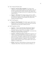
The configuration file shown below is not a complete configuration file. Rather, it
provides an example for using access lists on a Cisco router. The diagram below
shows the topology that this file is based on. The security policy implemented with
the access lists allows most traffic from the internal network to the external network.
The policy restricts most traffic from the external network to the internal network.
Other
networks
Router
Protected
network
14.2.6.0/24
Interface eth1
14.2.6.250/24
Interface eth0
14.1.1.20/16
hostname East
!
interface Ethernet0
description Outside interface to the 14.1.0.0/16 network
ip address 14.1.1.20 255.255.0.0
ip access-group 100 in
!
interface Ethernet1
description Inside interface to the 14.2.6.0/24 network
ip address 14.2.6.250 255.255.255.0
ip access-group 102 in
!
! access-list 75 applies to hosts allowed to gather SNMP info
! from this router
no access-list 75
access-list 75 permit host 14.2.6.6
access-list 75 permit host 14.2.6.18
!
! access-list 100 applies to traffic from external networks
! to the internal network or to the router
no access-list 100
access-list 100 deny ip 14.2.6.0 0.0.0.255 any log
access-list 100 deny ip host 14.1.1.20 host 14.1.1.20 log
access-list 100 deny ip 127.0.0.0 0.255.255.255 any log
access-list 100 deny ip 10.0.0.0 0.255.255.255 any log
access-list 100 deny ip 0.0.0.0 0.255.255.255 any log
access-list 100 deny ip 172.16.0.0 0.15.255.255 any log
access-list 100 deny ip 192.168.0.0 0.0.255.255 any log
access-list 100 deny ip 192.0.2.0 0.0.0.255 any log
access-list 100 deny ip 169.254.0.0 0.0.255.255 any log
access-list 100 deny ip 224.0.0.0 15.255.255.255 any log
access-list 100 deny ip any host 14.2.6.255 log
access-list 100 deny ip any host 14.2.6.0 log
access-list 100 permit tcp any 14.2.6.0 0.0.0.255 established
Version 1.1c 93
Router Security Configuration Guide
access-list 100 deny icmp any any echo log
access-list 100 deny icmp any any redirect log
access-list 100 deny icmp any any mask-request log
access-list 100 permit icmp any 14.2.6.0 0.0.0.255
access-list 100 permit ospf 14.1.0.0 0.0.255.255 host 14.1.1.20
access-list 100 deny tcp any any range 6000 6063 log
access-list 100 deny tcp any any eq 6667 log
access-list 100 deny tcp any any range 12345 12346 log
access-list 100 deny tcp any any eq 31337 log
access-list 100 permit tcp any eq 20 14.2.6.0 0.0.0.255 gt 1023
access-list 100 deny udp any any eq 2049 log
access-list 100 deny udp any any eq 31337 log
access-list 100 deny udp any any range 33400 34400 log
access-list 100 permit udp any eq 53 14.2.6.0 0.0.0.255 gt 1023
access-list 100 deny tcp any range 0 65535 any range 0 65535 log
access-list 100 deny udp any range 0 65535 any range 0 65535 log
access-list 100 deny ip any any log
!
! access-list 102 applies to traffic from the internal network
! to external networks or to the router itself
no access-list 102
access-list 102 deny ip host 14.2.6.250 host 14.2.6.250 log
access-list 102 permit icmp 14.2.6.0 0.0.0.255 any echo
access-list 102 permit icmp 14.2.6.0 0.0.0.255 any parameter-problem
access-list 102 permit icmp 14.2.6.0 0.0.0.255 any packet-too-big
access-list 102 permit icmp 14.2.6.0 0.0.0.255 any source-quench
access-list 102 deny tcp any any range 1 19 log
access-list 102 deny tcp any any eq 43 log
access-list 102 deny tcp any any eq 93 log
access-list 102 deny tcp any any range 135 139 log
access-list 102 deny tcp any any eq 445 log
access-list 102 deny tcp any any range 512 518 log
access-list 102 deny tcp any any eq 540 log
access-list 102 permit tcp 14.2.6.0 0.0.0.255 gt 1023 any lt 1024
access-list 102 permit udp 14.2.6.0 0.0.0.255 gt 1023 any eq 53
access-list 102 permit udp 14.2.6.0 0.0.0.255 any range 33400
34400 log
access-list 102 deny tcp any range 0 65535 any range 0 65535 log
access-list 102 deny udp any range 0 65535 any range 0 65535 log
access-list 102 deny ip any any log
!
! access-list 150 applies to admin access from specific hosts
no access-list 150
access-list 150 permit tcp host 14.2.6.10 host 0.0.0.0 eq 23 log
access-list 150 permit tcp host 14.2.6.11 host 0.0.0.0 eq 23 log
access-list 150 permit tcp host 14.2.6.12 host 0.0.0.0 eq 23 log
access-list 150 deny ip any any log
!
snmp-server community N3T-manag3m3nt ro 75
!
line vty 0 4
access-class 150 in
password 7 123456789012345678901234
login
transport input telnet
94 Version 1.1c
Advanced Security Services
4.3.5. Turbo Access Control Lists
Some Cisco router models support compiled access control lists, called “Turbo
ACLs”, in IOS 12.1(6), and later. Using compiled access control lists can greatly
reduce the performance impact of long lists. To enable turbo access lists on a router,
use the configuration mode command
access-list compiled. (If your IOS does
not support compiled access lists, the command will generate a harmless error
message.) Once this facility is enabled, IOS will automatically compile all suitable
access lists into fast lookup tables while preserving their matching semantics. Once
you have enabled turbo access lists, you can view statistics about them using the
command
show access-list compiled. If you use access lists with six or more
rules on high-speed interfaces, then compiled ACLs can give improved performance.
4.3.6. Rate Limiting with Committed Access Rate
Committed Access Rate (CAR) is a router service that gives administrators some
control over the general cross-section of traffic entering and leaving a router. By
allocating a specific amount of bandwidth to defined traffic aggregates, data passing
through the router can be manipulated to preserve fragile traffic, eliminate excessive
traffic, and limit spoofed traffic; however, the most important task that CAR can
perform is to mitigate the paralyzing effects of DoS attacks and flash crowds.
You can use CAR to reserve a portion of a link’s bandwidth for vital traffic, or to
limit the amount of bandwidth consumed by a particular kind of attack. In the latter
case, it may not be necessary to keep CAR rules in place at all times, but to be ready
to apply them quickly when you detect an attack in progress. This short section gives
an overview of CAR, and a few simple examples.
CAR Command Syntax
Configuring CAR requires you to apply rate limiting rules to each interface where
you enforce constraints on traffic or bandwidth usage. Each interface can have a
separate, ordered set of rules for the in-bound (receiving) and out-bound (sending)
directions. The general syntax for a CAR rule is shown below, somewhat simplified.
rate-limit {input | output} [access-group [rate-limit] acl]
token-bit-rate burst-normal-size burst-excess-size
conform-action action exceed-action action
To add a rule to an interface, simply type the rule in interface configuration mode, as
shown in the examples below. To remove a rule, enter it again adding the keyword
no to the front. To view the CAR rules on all the interfaces, use the command show
interface rate-limit
. The output of the command will show both the rules and
some traffic statistics about the rate limiting. A sample of the output is included in
the first example below.
For more information on CAR commands, consult the “IOS Quality of Service
Solutions Command Reference” section of the IOS documentation.
Version 1.1c 95
Router Security Configuration Guide
Defining Rules
Each rate limit rule is made up of 3 parts: the aggregate definition, the token bucket
parameters, and the action specifications.
• The aggregate definition section of a rule defines the kind of traffic (or
“packet aggregate”) to which the rule applies. The aggregate definition
must include the traffic direction, and may also include fine-grained traffic
selection specified with an access control list. If the rule is meant to apply
to packets entering the router, use the
input keyword; for packets leaving
the router use the
output keyword. If the aggregate definition includes
an
access-group clause, then the CAR rule will apply only to traffic that
is permitted by or matches that access list; if you supply no access-group
clause then the rule applies to all traffic. [It is also possible to apply CAR
rules to packets by QoS header and other criteria, but that is outside the
scope of this brief discussion.] If the keyword
rate-limit appears, it
indicates that the aggregate is defined by a rate-limit access list, otherwise
the access list should be a standard or extended IP access list. Rate-limit
access lists define aggregates based on IP precedence or MAC addresses.
• The second part of the rate-limit command is comprised of the three token
bucket parameters. The CAR facility uses a token bucket model to
allocate or limit bandwidth of traffic. This model gives you a flexible
method to stipulate bounds of traffic behavior for an aggregate. The token
bucket model needs three parameters for configuration: the token bit rate,
the traffic burst normal size (in bytes), and the traffic burst exccess size.
The token bit rate parameter must be specified in bits per second (bps), and
must be greater than 8000. It generally describes the allowed rate for the
aggregate. The burst normal size, given in bytes, is generally the size of a
typical traffic transaction in a single direction. For simple protocols, such
as ICMP or DNS, it would simply be the size of a typical message. The
burst excess size denotes the upper bound or maximum size expected for
traffic bursts, before the aggregate uses up its allocated bandwidth. For a
more detailed description of the token bucket model, consult [9].
• The last section of a rule consists of the two action specifications. The
first action instructs the router on how to handle packets when the
aggregate conforms to bandwidth allocation, and the second how to handle
packets when the aggregate exceeds its bandwidth allocation. Depending
on your IOS version, there may be as many as nine possible actions; the
most commonly used four are described below.
CAR Action Syntax Action Performed
drop
Discard the packet.
transmit
Transmit or forward the packet.
continue
Apply the next rate-limit rule.
96 Version 1.1c
Advanced Security Services
CAR Action Syntax Action Performed
set-prec-transmit prec
Set the IP precedence to prec and
transmit or forward the packet.
CAR Examples
In the first example, CAR is used to reserve 10% of a 10Mb Ethernet link for vital
outgoing SMTP traffic, and to limit outgoing ICMP ‘ping’ traffic to less than 1% of
the link. The rest of the link’s bandwidth will be usable by excess SMTP traffic and
all other IP traffic. In practice, you might want to impose both outbound and inbound
rate limiting to protect the vital SMTP traffic.
North(config)# no access-list 130
North(config)# access-list 130 permit tcp any any eq smtp
North(config)# no access-list 131
North(config)# access-list 131 permit icmp any any echo
North(config)# access-list 131 permit icmp any any echo-reply
North(config)# interface eth0/0
North(config-if)# rate-limit output access-group 130
1000000 25000 50000
conform-action transmit exceed-action continue
North(config-if)# rate-limit output access-group 131
16000 8000 8000
conform-action continue exceed-action drop
North(config-if)# rate-limit output 9000000 112000 225000
conform-action transmit exceed-action drop
North(config-if)# end
North# show interface rate-limit
Ethernet0/0
Output
matches: access-group 130
params: 1000000 bps, 25000 limit, 50000 extended limit
conformed 12 packets, 11699 bytes; action: transmit
exceeded 0 packets, 0 bytes; action: continue
last packet: 2668ms ago, current burst: 0 bytes
last cleared 00:02:32 ago, conformed 0 bps, exceeded 0 bps
matches: access-group 131
params: 16000 bps, 2500 limit, 2500 extended limit
conformed 130 packets, 12740 bytes; action: continue
exceeded 255 packets, 24990 bytes; action: drop
last packet: 7120ms ago, current burst: 2434 bytes
last cleared 00:02:04 ago, conformed 0 bps, exceeded 990 bps
matches: all traffic
params: 9000000 bps, 112000 limit, 225000 extended limit
conformed 346 packets, 27074 bytes; action: transmit
exceeded 0 packets, 0 bytes; action: drop
last packet: 7140ms ago, current burst: 0 bytes
last cleared 00:01:40 ago, conformed 2000 bps, exceeded 0 bps
North#
In this second example, CAR is being used to throttle a TCP SYN flood attack.
North(config)# no access-list 160
North(config)# access-list 160 deny tcp any any established
North(config)# access-list 160 permit tcp any any syn
North(config)# interface eth0/0
Version 1.1c 97
Router Security Configuration Guide
North(config-if)# rate-limit input access-group 160
64000 8000 8000
conform-action transmit exceed-action drop
North(config-if)# end
North#
The CAR rule in this example simply discards excessive TCP SYN packets. In this
case, legitimate traffic would also be affected. If you knew the general source of the
attack (perhaps an IP address range) then you could make the defense more selective
by incorporating the address range into the aggregate definition access list. For
another example of using CAR to combat a DoS attack, consult [10].
4.3.7. Control Plane Policing (CPP)
Conceptually, router operations can be abstracted into three planes: forwarding,
control, and management. The forwarding plane (also called the “data” plane)
forwards user data packets through the router. The management plane consists of
traffic for configuring and monitoring router operations. The control plane consists of
the routing, signaling and link management protocols. Timely and reliable operation
of the management and control planes are essential for maintaining the flow of traffic
through the forwarding plane.
Control Plane Policing (CPP) is a Cisco IOS feature that you can employ to counter
resource starvation-based DoS attacks that target the central processor of a router
(control plane and management plane). CPP protects the central processor via
policies that filter or rate limit traffic directed to the processor. Detailed information
about CPP may be found in a Cisco white paper [12].
To implement a CPP policy, all traffic destined for the control plane of a router must
be categorized into network administrator-defined groups or classes (e.g. the
“critical,” “normal,” “malicious,” and “default” classes). Then service policies
should be created and applied that cause traffic classes destined for the route
processor to be accepted, discarded, or rate limited. Take care when defining and
applying CPP policy it is easy to accidentally restrict the wrong traffic and disrupt
management or control plane services.
Before attempting to configure CPP, identify the classes you wish to handle, and
rough traffic rate limits for each of them. Once you have defined your classes,
setting up control plane policing on IOS requires four steps.
1. Create access lists that match (permit) the traffic from members of each
class. (If you have a ‘default’ class, do not create an access list for it.)
2. Define a named class map for each of the access lists you created in step
1, using the
class-map command.
3. Create a policy map using the
policy-map command. In the map, use
the
class map-name command to define rate-limiting policy for each
98 Version 1.1c
Advanced Security Services
named class. Define a default rate-limiting policy using the command
class class-default.
4. Apply your policy map to the control plane using the commands
control-plane and service-policy.
The example below shows how to configure CPP with three different classes: a
trusted class for internal and specific external hosts, a malicious class for a known
hostile host, and a default class for all other addresses. Traffic from hosts in the
trusted class will have no rate limits. Traffic from the malicious host will be dropped
entirely. Traffic from all other hosts will be rate-limited to 150 packets per second.
When planning your CPP rate limits, consider the bandwidth from possibly hostile
sites, and the bandwidth required to maintain router operations.
North# config t
Enter configuration commands, one per line. End with CNTL/Z.
North(config)# ! define ACL for CPP trusted hosts
North(config)# access-list 151 permit ip 14.1.0.0 0.0.255.255 any
North(config)# access-list 151 permit ip 14.2.0.0 0.0.255.255 any
North(config)# access-list 151 permit ip host 7.12.1.20 any
North(config)# ! define ACL for known hostile host
North(config)# access-list 152 permit ip host 1.2.3.4 any
North(config)# ! define a class mapping for trusted host
North(config)# class-map match-any cpp-trusted
North(config-cmap)# match access-group 151
North(config-cm exitap)#
North(config)# ! define a class mapping for the malicious host
North(config)# class-map match-any cpp-malicious
North(config-cmap)# match access-group 152
North(config-cm exitap)#
North(config)# ! define our CPP policy map
North(config)# policy-map cpp-policy
North(config-pmap)# class cpp-trusted
North(config-pmap-c)# ! no action here, allow any rate
North(config-pmap-c)# exit
North(config-pmap)# class cpp-malicious
North(config-pmap-c)# ! drop all traffic in this class
North(config-pmap-c)# police rate 10 pps
North(config-pmap-c-police)# conform-action drop
North(config-pmap-c-police)# exceed-action drop
North(config-pmap-c-police)# exit
North(config-pmap-c) exit#
North(config-pmap)# class class-default
North(config-pmap-c)# ! rate-limit all other traffic
North(config-pmap-c)# police rate 150 pps
North(config-pmap-c-police)# conform-action transmit
North(config-pmap-c-police)# exceed-action drop
North(config-pmap-c-police)# exit
North(config-pmap-c)# exit
North(config-pm exitap)#
North(config)# ! apply the policy map for CPP
North(config)# control-plane
North(config-cp)# service-policy input cpp-policy
North(config-cp)# end
North#
Version 1.1c 99
Router Security Configuration Guide
To view the current CPP policy and traffic statistics, use the command
show policy-map control-plane.
To remove a CPP policy, use the command
no service-policy command as
shown below.
North(config)# control-plane
North(config-cp)# no service-policy input cpp-policy
North(config-cp)# end
North#
4.3.8. References
[1] Chapman, D. Brent and Zwicky, Elizabeth D., Building Internet Firewalls,
O’Reilly Associates, 1995.
This text provides valuable information on how to packet filter many of the
commonly used services, e.g., SMTP, FTP, Telnet, etc.
[2] Karrenberg, D., Moskowitz, B. and Rekhter, Y. “Address Allocation for Private
Internets”, RFC 1918, February 1996.
This RFC describes the IP address allocation for private intranets. The
Internet Assigned Numbers Authority has reserved the following three blocks
of the IP address space for private intranets: 10.0.0.0 - 10.255.255.255,
172.16.0.0 - 172.31.255.255, and 192.168.0.0 - 192.168.255.255.
[3] Held, G., and Hundley, K., Cisco Access List Field Guide, McGraw-Hill, 1999.
This book offers detailed information about access control lists and many
examples of list syntax and usage.
[4] Held, G., and Hundley, K., Cisco Security Architectures, McGraw-Hill, 1999
This book includes a good introduction to router security, and a good primer
on access lists
[5] Cisco IOS Release 12.0 Security Configuration Guide, Cisco Press, 1999.
This is the reference manual and guide for major security features in IOS
12.0. It includes information on TCP Intercept, reflexive access lists, and
dynamic access lists.
[6] Ferguson, P. and Senie, D. “Network Ingress Filtering: Defeating Denial of
Service Attacks which employ IP Source Address Spoofing”, RFC 2827, 2000.
This Internet ‘Best Current Practice’ RFC gives a good overview of source
address filtering.
100 Version 1.1c
Advanced Security Services
[7] Greene, B. and Smith, P., Cisco ISP Essentials, 1st Edition, Cisco Press, April
2002.
This detailed Cisco guide for Internet Service Providers includes extensive
discussion of routing protocols (especially BGP), and an in-depth treatment
of Unicast RPF, all with fully worked-out examples.
[8] Sedayao, J., Cisco IOS Access Lists, O’Reilly Associates, 2001.
A detailed guide to access lists, including coverage of using access lists with
routing protocols.
[9] “Selecting Burst and Extended Burst Values for Class-based Policing”, Cisco
Tech Note, Cisco Systems, Feb 2002.
available at:
Describes the CAR token bucket model and burst size parameters in some
depth; gives guidance on how to select usable values.
[10] “Using CAR During DOS Attacks”, Cisco Tech Note, Cisco Systems, 2001.
available at:
Walks through a detailed CAR example related to ICMP flooding.
[11] Baker, F. and Savola, P., “Ingress Filtering for Multihomed Networks”, RFC
3704, March 2004.
Detailed directions for doing RFC 2827-compliant filtering on networks
connected to multiple providers.
[12] “Deploying Control Plane Policing”, Cisco white paper, Cisco Systems, 2005.
available under:
ps6642/prod_white_papers_list.html
This white paper explains the motivations for CPP and provides detailed
instructions on how to configure it. It also lists the Cisco IOS releases that
support CPP.
Version 1.1c 101
Router Security Configuration Guide
4.4. Routing and Routing Protocols
“A protocol is a formal description of a set of rules and conventions that govern how
devices on a network exchange information.”[5] This section will discuss two basic
types of protocols, with a focus on the latter. The two types of protocols are:
• Routed protocols –
These are protocols that can be routed by a router. The routed protocol
allows the router to correctly interpret the logical network. Some examples
of routed protocols are IP, IPX, AppleTalk, and DECnet.
• Routing protocols –
“A routing protocol gathers information about available networks and the
distance, or cost, to reach those networks.”[7] These protocols support
routed protocols and are used to maintain routing tables. Some examples
of routing protocols are OSPF, RIP, BGP, IS-IS, and EIGRP.
All of the examples in this section are based on the sample network architecture
shown in Figure 4-1.
Routed Protocols
The most commonly used routed network protocol suite is the TCP/IP suite; its
foundation is the Internet Protocol (IP). This section will not provide an in-depth
discussion of this protocol, as that is far beyond the scope of this guide, consult [6]
for a detailed introduction. ARPA sponsored the development of IP over twenty-five
years ago under the ARPANET project. Today, it is the basis for the worldwide
Internet. Its growth and popularity can be attributed to IP’s ability to connect
different networks regardless of physical environment, and the flexible and open
nature of the IP network architecture.
IP is designed for use on large networks; using IP, a connected host anywhere on a
network can communicate with any other. In practice, host applications almost never
use raw IP to communicate. Instead, they use one of two transport-layer protocols
built on top of IP: the Transmission Control Protocol (TCP) or the User Datagram
Protocol (UDP). Use of TCP or UDP is immaterial to routing, which takes place
exclusively at the network layer. Each IP host does not need to know a path through
the network to every other host, instead it only needs to know the address of one or a
small number of routers. These routers are responsible for directing each IP packet to
its intended destination.
In a small network, each router can simply be connected directly to every other
router. For larger networks, of course, connecting every router to every other would
be prohibitively expensive. Instead, each router maintains a route table with
information about how to forward packets to their destination addresses. Correct,
efficient, and secure operation of any large IP network depends on the integrity of its
route tables. For a detailed introduction to the concepts of routing, consult [16].
102 Version 1.1c
Advanced Security Services
Route Tables and Routing Protocols
A router’s primary responsibility is to send a packet of data to the intended
destination. To accomplish this, each router needs a route table. Each router builds
its table based on information from the network and from the network administrators.
The router then uses a set of metrics, depending on the contents of the table and its
routing algorithm, to compare routes and to determine the ‘best’ path to a destination.
Routers use four primary mechanisms for building their route tables:
1. Direct connection: Any LAN segment to which the router is directly
connected is automatically added to the route table. For example, the
router Central is connected to the LAN segment 14.2.9.0/24.
2. Static routing. As network administrator, you can manually instruct a
router to use a given route to a particular destination. This method
usually takes precedence over any other method of routing.
3. Dynamic routing. Uses router update messages from other routers to
create routes. The routing algorithm associated with the particular
routing protocol determines the optimal path to a particular destination,
and updates the route table. This method is the most flexible because it
can automatically adapt to changes in the network.
4. Default routing. Uses a manually entered route to a specific ‘gateway of
last resort’ when route is not known by any other routing mechanism.
This method is most useful for border routers and routers that serve as
the sole connection between a small LAN and a large network like the
Internet. Routers that depend on a single default gateway usually do not
use routing protocols.
Although many different dynamic routing protocols exist, they can be divided into
two groups: interior and exterior gateway protocols. An interior gateway protocol
(IGP) is used for exchanging routing information between gateways within an
autonomous system. An autonomous system is a group of networking components
under one administrative domain. The gateways within the autonomous system use
the route information conveyed by the IGP messages to direct IP traffic. An exterior
gateway protocol (EGP) is used between autonomous systems. It is typical, although
not universal, that interior gateway protocols are employed on interior routers, and
exterior gateway protocols on backbone routers. Border routers might use either, or
both, depending on the network architecture in which they are found. Border
Gateway Protocol version 4 (BGP-4) is the exterior gateway protocol used for
conveying route information between autonomous systems on the Internet.
This section focuses on a small number of widely used routing protocols: RIP, OSPF,
BGP, IS-IS, and EIGRP. The first three are IETF standards, IS-IS is an ISO
standard, and the last, EIGRP, is vendor-defined. RIP, the Routing Information
Protocol, is an example of a distance vector based interior gateway protocol. OSPF,
Version 1.1c 103
Router Security Configuration Guide
Open Shortest Path First, and IS-IS, Intermediate-System to Intermediate-System, are
examples of link state interior gateway protocols. BGP-4, the Border Gateway
Protocol, version 4, is the IETF standard exterior gateway protocol. EIGRP, the
Enhanced Interior Gateway Routing Protocol, is a proprietary Cisco IGP that is
sometimes used in all-Cisco networks. The table below provides a short comparison.
Table 4-2 – Five Popular IP Routing Protocols
RIP
Distance vector protocol: maintains a list of distances to other networks
measured in hops, the number of routers a packet must traverse to reach its
destination. RIP is suitable only for small networks, partly because the
maximum distance is 15 hops. Broadcasts updates every 30 seconds to
neighboring RIP routers to maintain integrity. Each update is a full route table.
OSPF
Link state protocol: uses a link speed-based metric to determine paths to other
networks. Each router maintains a simplified map of the entire network.
Updates are sent via multicast, and are sent only when the network
configuration changes. Each update only includes changes to the network.
OSPF is suitable for large networks.
IS-IS
Link state protocol: uses a cost-based metric by default to determine paths to
other networks. Optional metrics are delay, expense and error. Cisco IOS
supports only the cost based metric. Routers establish and maintain neighbor
adjacencies every 10 seconds by default. A complete link state database is
broadcast by a designated router every 10 seconds by default to synchronize
neighbor route tables. IS-IS is suitable for large networks.
EIGRP
Distance vector protocol: maintains a complex set of metrics for the distance to
other networks,and incorporates some features of link state protocols.
Broadcasts updates every 90 seconds to all EIGRP neighbors. Each update
includes only changes to the network. EIGRP is suitable for large networks.
BGP
A distance vector exterior gateway protocol that employs a sophisticated series
of rules to maintain paths to other networks. Updates are sent over TCP
connections between specifically identified peers. BGP-4 employs route
aggregation to support extremely large networks (e.g. the Internet).
Another important aspect of a routing protocol scheme is the amount of time it takes
for network architecture or connectivity changes to be reflected in the route tables of
all affected routers. This is usually called the rate of convergence. For example, in a
large network OSPF offers much faster convergence than RIP.
Configuring routing in IP networks can be a very complex task, and one which is
outside the scope of this guide. Routing does raise several security issues, and Cisco
IOS offers several security services for routing; this section discusses some of these
security issues and describes several of the security services in moderate detail. For
general guidance on routing protocols, consult the Cisco IOS documentation, or [3].
4.4.1. Common routing hazards
A question that is often overlooked is “Why do we need to concern ourselves with
security of the network?” A better question to ask would be “What kind of damage
104 Version 1.1c
Advanced Security Services
could an adversary do to our network?” Section 3 presents some motivations for
overall router security. This section focuses on security issues related to routing and
routing protocols. Routing security should be a top priority for network
administrators who want to:
• prevent unauthorized access to resources on the network,
• protect mission information from unauthorized exposure and modification,
• prevent network failures and interruptions in service.
An unprotected router or routing domain makes an easy target for any network-savvy
adversary. For example, an attacker who sends false routing update packets to an
unprotected router can easily corrupt its route table. By doing this, the attacker can
re-route network traffic in whatever manner he desires. The key to preventing such
an attack is to protect the route tables from unauthorized and malicious changes.
There are two basic approaches available for protecting route table integrity:
1. Use only static routes –
This may work in small networks, but is unsuitable for large networks
because it increases administrative overhead and requires administrative
response to any failures.
2. Authenticate route table updates –
By using routing protocols with authentication, network administrators
can deter attacks based on unauthorized routing changes. Authenticated
router updates ensure that the update messages came from legitimate
sources, bogus messages are automatically discarded.
Another form of attack an adversary might attempt against a router is a denial of
service attack. This can be accomplished in many different ways. For example,
preventing router update messages from being sent or received will result in bringing
down parts of a network. To resist denial of service attacks, and recover from them
quickly, routers need rapid convergence and backup routes.
A detailed analysis of routing protocol threats and countermeasures may be found in
a Cisco SAFE white paper [45].
4.4.2. ARP and LANs
Address Resolution Protocol, or ARP, is the protocol used to map IP addresses to a
particular MAC or Ethernet address. ARP is described in more detail in RFC 826 and
Parkhurst [2]. Proxy ARP is a method of routing packets using the Ethernet MAC
address instead of the IP address to determine the final destination of a packet. For a
detailed description of Proxy ARP, consult RFC 1027.
However, because ARP offers no security, neither does Proxy ARP. The fundamental
security weakness of ARP is that it was not designed to use any form of
authentication. Anyone on a LAN segment can modify an entry in the ARP cache of
Version 1.1c 105
Router Security Configuration Guide
a router that serves the segment. Therefore, if a host on the network does not use
default gateways, but instead uses Proxy ARP to handle the routing, it is susceptible
to bad or malicious routes. In any case, Proxy ARP is generally not used anymore,
and it should be disabled. The following example illustrates how to do just that.
Central# config t
Enter configuration commands, one per line. End with CNTL/Z.
Central(config)# interface ethernet0/0
Central(config-if)# no ip proxy-arp
Central(config-if)# exit
Central(config)# interface ethernet0/1
Central(config-if)# no ip proxy-arp
Central(config-if)# end
Central#
4.4.3. Route tables, static routes, and routing protocols
This section describes how to protect routers from some common routing hazards.
The main focus of this section is using peer router authentication with interior
gateway protocols. Section 4.4.5 gives some security guidance for one exterior
gateway protocol, BGP-4.
Router Neighbor Authentication
The primary purpose of router neighbor authentication is to protect the integrity of a
routing domain. In this case, authentication occurs when two neighboring routers
exchange routing information. Authentication ensures that the receiving router
incorporates into its tables only the route information that the trusted sending router
really intended to send. It prevents a legitimate router from accepting and then
employing unauthorized, malicious, or corrupted routing updates that would
compromise the security or availability of a network. Such a compromise might lead
to re-routing of traffic, a denial of service, or simply giving access to certain packets
of data to an unauthorized person.
OSPF Authentication
Router neighbor authentication is a mechanism that, when applied correctly, can
prevent many routing attacks. Each router accomplishes authentication by the
possession of an authentication key. That is, routers connected to the same network
segment all use a shared secret key. Each sending router then uses this key to ‘sign’
each route table update message. The receiving router checks the shared secret to
determine whether the message should be accepted. This sub-section describes the
implementation of router neighbor authentication in OSPF, because it is a good
illustration of the basic principle; authentication in RIP version 2 and EIGRP work in
a similar fashion.
OSPF uses two types of neighbor authentication: plaintext and message digest
(MD5). Plaintext authentication uses a shared secret key known to all the routers on
the network segment. When a sending router builds an OSPF packet, it signs the
106 Version 1.1c
Advanced Security Services
packet by placing the key as plaintext in the OSPF header. The receiving router then
compares the received key against the key in memory. If the keys match, then the
router accepts the packet. Otherwise, the router rejects the packet. This method does
not provide much security because the key is in plaintext in the packet. Using this
method reveals the secret key to any attacker using a network sniffer on the right
LAN segments. Once an attacker captures the key, they can pose as a trusted router.
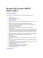
The second, and more secure method, is message digest authentication. Figure 4-3
shows our example network with its routing protocols.
OSPF
Area 0
Internet
Central
East
Facility
Network
14.1.0.0/16
North
South
Second Floor
14.2.9.0/24
14.2.10.0/24
eth0/1
14.2.6.0/24
eth1
eth0/1
eth0
eth0/0
eth0/0
eth0/1
eth0/0
14.2.10.64/24
14.2.9.64/24
14.2.9.250/24
14.1.15.250/16
14.1.1.250/16
14.2.6.250/24
14.1.1.20/16
RIP
Autonomous System Border Router (ASBR)
Figure 4-3: An Example Routing Architecture
In this example, routers North, East, and Central all share the same secret key,
r0utes-4-all, with a Key ID of 1. Each of these routers authenticates to each
other using the MD5 message digest authentication method, whose cryptographic
Version 1.1c 107
Router Security Configuration Guide
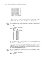
authentication type is denoted by a value of 2. Figure 4-4 shows how East
authenticates to North. East first builds an OSPF packet, both header and body. It
then picks a primary key to use on the network segment. In this case, the key is
r0utes-4-all. The corresponding Key ID, 1, is placed in the header. East also
places a 32-bit sequence number in the header. This sequence number protects
against replay attacks so that no two OSPF packets will have the same hash value.
The sequence number is incremented with every new packet. Finally, the secret key
is appended to the packet. East runs the cryptographic hash algorithm, MD5, against
the OSPF packet. The output, 16 bytes, is written over the secret that was appended
to the packet.
The receiving router, North, looks at the Key ID to determine which key was used to
generate the hash, or signature. The router then uses its own key to regenerate the
hash on the received packet in the same manner as the sending router. If the
regenerated hash matches the hash that was sent from East, then the North trusts the
packet. Otherwise, it rejects the packet as being invalid.
OSPF Version OSPF pkt type
OSPF length
Source OSPF Router ID
OSPF Area ID
0 (no checksum)
2 (cryptographic auth type)
0
1 (Key ID) 16 (MD5 len)
Cryptographic sequence number
OSPF packet body
16-byte secret
OSPF Version OSPF pkt type
OSPF length
Source OSPF Router ID
OSPF Area ID
0 (no checksum)
2 (cryptographic auth type)
0
1 (Key ID) 16 (MD5 len)
Cryptographic sequence number
OSPF packet body
MD5
cryptographic
hash
MD5 hash
algorithm
Figure 4-4: OSPF Calculation of an MD5 Authentication Signature (from [4])
OSPF Plaintext Authentication
This method is not recommended, use the superior MD5 method.
108 Version 1.1c
Advanced Security Services
OSPF MD5 Authentication
The example below illustrates an example of setting up MD5 for OSPF router
neighbor authentication. The example transcripts below show routers North and East
receiving the key
r0utes-4-all. In practice, all the routers participating in a given
network should be configured in the same way, using the same key. Using the
example network shown in Figure 4-1, router Central would also have to be
configured with MD5 authentication and the same shared key as shown below.
North# config t
Enter configuration commands, one per line. End with CNTL/Z.
North(config)# router ospf 1
North(config-router)# network 14.1.0.0 0.0.255.255 area 0
North(config-router)# area 0 authentication message-digest
North(config-router)# exit
North(config)# int eth0/1
North(config-if)# ip ospf message-digest-key 1 md5 r0utes-4-all
North(config-if)# end
North#
East# config t
Enter configuration commands, one per line. End with CNTL/Z.
East(config)# router ospf 1
East(config-router)# area 0 authentication message-digest
East(config-router)# network 14.1.0.0 0.0.255.255 area 0
East(config-router)# network 14.2.6.0 0.0.0.255 area 0
East(config-router)# exit
East(config)# int eth0
East(config-if)# ip ospf message-digest-key 1 md5 r0utes-4-all
East(config-if)# end
East#
RIP Authentication
The RIP routing protocol also supports authentication to prevent routing attacks.
RIP’s method of authentication is very similar to that of OSPF, although the IOS
commands are somewhat different. The neighboring RIP routers use shared secret
keys. Each sending router uses these keys to generate the cryptographic hash
incorporated into each RIP update message. The receiving router then uses the shared
secret to check the hash and determine whether the message should be accepted.
RIP Plaintext Authentication
This method is not recommended, use the superior MD5 method, below.
RIP MD5 Authentication
The example below illustrates an example of setting up MD5 for RIP router neighbor
authentication. The example transcripts below show routers from Figure 4-3, Central
and South, receiving the key my-supersecret-key, contained in their respective
Version 1.1c 109
Router Security Configuration Guide
key chains. In practice, all the routes connected to a given network must be
configured in the same way. That is, all of them must possess the same shared key(s).
Prior to enabling RIP MD5 authentication, each neighboring router must have a
shared secret key. RIP manages authentication keys by the use of key chains. A key
chain is a container that holds multiple keys with the associated key IDs and key
lifetimes. Multiple keys with different lifetimes can exist. However, only one
authentication packet is sent. The router examines the key numbers in order from
lowest to highest, and uses the first valid key that is encountered. In the example
below, Central and South have key chains named CENTRAL-KC and SOUTH-KC.
Both key chains share the keys my-supersecret-key and my-othersecret-
key. However, both routers will only use the first valid key. The other key is usually
used when migrating to different keys.
Central# config t
Enter configuration commands, one per line. End with CNTL/Z.
Central(config)# key chain CENTRAL-KC
Central(config-keychain)# key 1
Central(config-keychain-key)# key-string my-supersecret-key
Central(config-keychain-key)# exit
Central(config-keychain)# key 2
Central(config-keychain-key)# key-string my-othersecret-key
Central(config-keychain-key)# end
Central#
South# config t
Enter configuration commands, one per line. End with CNTL/Z.
South(config)# key chain SOUTH-KC
South(config-keychain)# key 1
South(config-keychain-key)# key-string my-supersecret-key
South(config-keychain-key)# exit
South(config-keychain)# key 2
South(config-keychain-key)# key-string my-othersecret-key
South(config-keychain-key)# end
South#
RIP version 1 did not support authentication. This was a feature that was included in
RIP version 2. Each RIP router must first be configured to use version 2 in order to
enable authentication during routing updates. The example below shows how to
enable version 2 of RIP.
Central# config t
Enter configurati , one per line. End with CNTL/Z. on commands
Central(config)# router rip
Central(config-router)# version 2
Central(config-router)# network 14.0.0.0
Central(config-router)# end
Central#
South# config t
Enter configuration commands, one per line. End with CNTL/Z.
110 Version 1.1c
Advanced Security Services
South(config)# router rip
South(config-router)# version 2
South(config-router)# network 14.0.0.0
South(config-router)# end
South#
Finally, the example below shows how to enable authentication for RIP.
Authentication for RIP is enabled on the interfaces. In the example below, Central
will be using the key chain CENTRAL-KC that was created earlier and the MD5
method of authentication.
Central# config t
Enter configuration commands, one per line. End with CNTL/Z.
Central(config)# int ethernet0/1
Central(config-if)# ip rip authentication key-chain CENTRAL-KC
Central(config-if)# ip rip authentication mode md5
Central(config-if)# end
Central#
South# config t
Enter configuration commands, one per line. End with CNTL/Z.
South(config)# int ethernet0/0
South(config-if)# ip rip authentication key-chain SOUTH-KC
South(config-if)# ip rip authentication mode md5
South(config-if)# end
South#
EIGRP Authentication
EIGRP route authentication is provided through the use of a keyed Message Digest 5
(MD5) hash. This insures the integrity of routing messages accepted from
neighboring routers. To configure EIGRP authentication:
1. Select the MD5 authentication mode.
2. Enable authentication for EIGRP messages.
3. Specify the key chain, key number, and key string to be used.
4. Configure key management (optional).
The example below details the steps necessary to configure MD5 authentication on
two EIGRP peers, North and East. Initially, EIGRP is configured on both routers for
the 14.1.0.0/16 network. Proceeding into the interface configuration mode, MD5
authentication is enabled within autonomous system 100 and linked to a particular
key chain. Router North’s key chain is defined as
northkc and router East’s key
chain is named
eastkc. The key chain name is locally significant and neighboring
routers do not have to be configured with the same name. Finally, the key chain is
defined within key chain configuration mode consisting of a key name, key number,
and key string. In this example, Router North has associated key number 1 with the
Version 1.1c 111
Router Security Configuration Guide
key-string ‘secret-key’. Key management is optionally configured with the accept-
lifetime and send-lifetime commands. In this case, the routers will send updates
authenticated with the key ‘my-secret-key’ from October 1, 2003 until January 1,
2004; it will accept updates with that key until January 7, 2004. The examples
below show how to configure EIGRP authentication and keys.
North# config t
Enter configuration commands, one per line.End with CNTL/Z.
North(config)# router eigrp 100
North(config-router)# network 14.1.0.0 255.255.0.0
North(config-router)# exit
North(config)# interface eth 0/1
North(config-if)# ip authentication mode eigrp 100 md5
North(config-if)# ip authentication key-chain eigrp 100 NORTH-KC
North(config-if)# exit
North(config)# key chain NORTH-KC
North(config-keychain)# key 1
North(config-keychain-key)# key-string my-secret-key
North(config-keychain-key)# send-lifetime 00:00:00 Oct 1 2003
00:00:00 Jan 1 2004
North(config-keychain-key)# accept-lifetime 00:00:00 Oct 1 2003
00:00:00 Jan 7 2004
North(config-keychain-key)# end
North#
East# config t
Enter configuration commands, one per line. End with CNTL/Z.
East(config)# router eigrp 100
East(config-router)# network 14.1.0.0 255.255.0.0
East(config-router)# network 14.2.6.0 255.255.255.0
East(config-router)# passive-interface eth1
East(config-router)# exit
East(config)# interface eth 0
East(config-if)# ip authentication mode eigrp 100 md5
East(config-if)# ip authentication key-chain eigrp 100 EAST-KC
East(config-if)# exit
East(config)# key chain EAST-KC
East(config-keychain)# key 1
East(config-keychain-key)# key-string my-secret-key
East(config-keychain-key)# send-lifetime 00:00:00 Oct 1 2003
00:00:00 Jan 1 2004
East(config-keychain-key)# accept-lifetime 00:00:00 Oct 1 2003
00:00:00 Jan 7 2004
East(config-keychain-key)# end
East#
It is important to note that each key string is associated with a specific key number.
In the example above, the key-string “secret-key” is associated with key number 1.
Multiple keys and key-strings can be configured on a router, but only one
authentication packet is sent. The router chooses the first valid key while examining
the key numbers from lowest to highest.
112 Version 1.1c
Advanced Security Services
IS-IS Authentication
IS-IS provides three methods of authentication to prevent routing attacks: Plaintext
(or clear text), Enhanced Clear Text and Hashed Message Authentication Code
Message Digest 5 (HMAC-MD5). Plaintext authentication uses a shared secret key
known to all the routers on the network segment. This method does not provide much
security because the key is in plaintext in the packet. Using this method reveals the
secret key to any attacker using a network sniffer on the associated LAN segments.
Once an attacker captures the key, they can pose as a trusted router. Enhanced Clear
Text authentication functions like Plaintext authentication with the exception that the
authenticating key is encrypted only within the configuration of the router. The final,
and recommended security practice is to use HMAC-MD5 authentication. This
method sends a “message digest” instead of the authenticating key itself. The
message digest is created using a shared secret key and a message, but the key itself
is not sent, preventing it from being read while it is being transmitted.
The IS-IS HMAC-MD5 authentication feature adds an HMAC-MD5 digest to each
IS-IS protocol data unit (PDU) packet before transmitting the packet across the
network. The digest is used by the receiving router(s) to authenticate each PDU. This
process prevents unauthorized PDUs from being accepted and used in the IS-IS
routing domain.
IS-IS has five PDU packet types: LSP, LAN Hello, Serial Hello CNSP and PSNP.
The IS-IS HMAC-MD5 authentication can be applied to all five types of PDU. The
authentication can be enabled on the two different IS-IS Levels (Level 1 and Level 2)
independently. “The interface-related PDUs (LAN Hello, Serial Hello, CNSP and
PSNP) can be enabled with authentication on different interfaces, with different
levels and different passwords.” [26]
In order to use IS-IS HMAC-MD5 authentication, you must configure the following
three things:
1. a key chain,
2. an IS-IS routing protocol instance, and
3. HMAC-MD5 authentication.
The keys on the key chain must be identical on neighboring routers. Each sending
router uses its keys to generate the cryptographic hash incorporated into IS-IS
messages. The receiving router then uses its identical set of keys to check the IS-IS
authentication. The transcripts below show routers from Figure 4-5, North and East,
being configured with the key
my-secret-key, in their respective key chains.
North# config t
Enter configuration commands, one per line. End with CNTL/Z.
North(config)# key chain ISIS-KC
North(config-keychain)# key 1
North(config-keychain-key)# key-string my-secret-key
North(config-keychain-key)# end
North#
Version 1.1c 113
Router Security Configuration Guide
East# config t
Enter configuration commands, one per line. End with CNTL/Z.
East(config)# key chain ISIS-KC
East(config-keychain)# key 1
East(config-keychain-key)# key-string my-secret-key
East(config-keychain-key)# end
East#
Internet
Central
East
Facility
N
etwor
k
14.1.0.0/16
N
orth
14.2.6.0/24
eth1
eth0/1
eth0
eth0/0
eth0/0
14.1.15.250/16
14.1.1.250/16
14.2.6.250/24
14.1.1.20/16
IS-IS
Area 49.0001
N
ET = 49.0001.0000.0000.0001.00
N
ET = 49.0001.0000.0000.0003.00
Figure 4-5: An Example Routing Architecture
Next, ensure the IS-IS routing protocol process is running on the routers. Then select
the IS-IS PDU types to authenticate and enable IS-IS HMAC-MD5 authentication on
the routers. For example, a site’s security policy may require that routers authenticate
to establish neighbor adjacencies within an area and perhaps it requires that routers
authenticate before accepting routing database updates within an area. The following
scripts implement this security policy. Notice that IS-IS HMAC-MD5 authentication
is applied to the North router’s ethernet interface 0/1 and on the East router’s ethernet
interface 0 to authenticate neighbor adjacencies (i.e. LAN Level 1: Hello packets).
Also notice that IS-IS HMAC-MD5 authentication is applied to the IS-IS instance to
authenticate routing database updates (i.e. Level 1: LSP, CNSP, and PSNP packets):
North# config t
Enter configuration commands, one per line. End with CNTL/Z.
North(config)# router isis secure-network
North(config-router)# net 49.0001.0000.0000.0001.00
North(config-router)# is-type level-1
North(config-router)# authentication mode md5 level-1
North(config-router)# authentication key-chain ISIS-KC level-1
North(config-router)# exit
North(config)# interface ethernet 0/1
North(config-if)# ip address 14.1.1.250 255.255.0.0
North(config-if)# ip router isis secure-network
114 Version 1.1c
Advanced Security Services
North(config-if)# isis authentication mode md5 level-1
North(config-if)# isis authentication key-chain ISIS-KC level-1
North(config-if)# end
North#
East# config t
Enter configuration commands, one per line. End with CNTL/Z.
East(config)# router isis secure-network
East(config-router)# net 49.0001.0000.0000.0003.00
East(config-router)# is-type level-1
East(config-router)# authentication mode md5 level-1
East(config-router)# authentication key-chain ISIS-KC level-1
East(config-router)# exit
East(config)# interface ethernet 0
East(config-if)# ip address 14.1.1.20 255.255.0.0
East(config-if)# ip router isis secure-network
East(config-if)# isis authentication mode md5 level-1
East(config-if)# isis authentication key-chain ISIS-KC level-1
East(config-if)# end
East#
Authentication on Level 2 packets is accomplished by changing the level-1 parameter
in the example above to level-2.
IS-IS offers a unique security advantage compared to other IP routing protocols. IS-
IS packets are encapsulated over the data link and are not carried in IP packets.
Therefore an attacker has to be physically attached to a router in the IS-IS network to
maliciously disrupt the IS-IS routing environment. “Other routing protocols, such as
RIP, OSPF and BGP, are susceptible to attacks from remote IP networks through the
Internet because routing protocol packets are ultimately embedded in IP packets,
which makes them susceptible to remote access by intrusive applications.” [27]
Key Management
The strength of these methods, RIP, OSPF, IS-IS, and EIGRP routing update
authentication, depends on two factors: the secrecy of the keys and the quality of the
keys. A key’s secrecy is intact only if it is known by the trusted routers but hidden
from any attacker. The best method for distributing keys to trusted routers is to do it
manually. The other issue with maintaining secrecy is the question of “How many
keys should be used in the routing domain?” That is, whether one key should be used
for the entire routing domain, or a separate key for each router neighbor-to-neighbor
connection. Using a separate key for each router neighbor-to-neighbor connection
can become an administrative nightmare, so using a common key for the entire
routing domain is recommended. However, maintaining the secrecy of the key
becomes much more important, because failure to do so can compromise the entire
network. Key lifetime is also important. RIP, IS-IS, and EIGRP use Cisco IOS key
chains, which offer substantial control over key lifetime. OSPF uses single keys; an
administrator must manually change the keys when their lifetimes expire.
Version 1.1c 115
Router Security Configuration Guide
Management of key lifetime is accomplished optionally through the use of the
keychain
accept-lifetime and send-lifetime commands. Both of these are
configured within the key chain configuration mode, and specify the start-time and
end-time to accept and send individual keys. These commands apply to keys in a
keychain, so they can be used for IS-IS, EIGRP, and RIPv2 authentication, but not
OSPF authentication. The router must be configured to maintain correct time (see
Section 4.5.2). The number of different keys and the key validity periods should be
defined in the router security policy.
The other factor that authentication relies upon is the quality of the keys. The rules
for generating good passwords apply to generating good keys as well. See Section 4.1
for a detailed description.
If you use routing update authentication, then your router security policy should
define the key management procedures and responsibilities.
Static Routes
Static routes are manually configured on the router as the only path to a given
destination. These routes typically take precedence over routes chosen by dynamic
routing protocols.
In one sense, static routes are very secure. They are not vulnerable to spoofing
attacks because they do not deal with router update packets. Using static routes
exclusively can make network administration very difficult. Also, configuring a
large network to use only static routes can make the availability of large pieces of the
network subject to single points of failure. Static routes cannot easily handle events
that change the network topology, such as link failures. A dynamic routing protocol,
such as OSPF, can correctly re-route traffic in the case of a router or link failure.
In most cases, static routes take precedence over their dynamic counterparts.
However, if an administrative distance is specified, then that static route can be
overridden by dynamic information. For example, OSPF-derived routes have a
default administrative distance of 110. Thus a static route must have an
administrative distance greater than 110 if the OSPF derived route is to have
precedence over the static route. Static routes have a default administrative distance
of 1.
The following example illustrates how to create a static route with a higher
administrative distance than OSPF. For more information on the internal workings of
static routes, consult [7].
Central# config t
Enter configuration commands, one per line. End with CNTL/Z.
Central(config)# ip route 14.2.6.0 255.255.255.0 14.1.1.20 120
Central(config)# end
Central#
116 Version 1.1c