how to cheat at securing a wireless network phần 5 potx
Bạn đang xem bản rút gọn của tài liệu. Xem và tải ngay bản đầy đủ của tài liệu tại đây (288.36 KB, 47 trang )
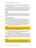
As shown in Figure 5.7, radio interface “0” has been split into “0.1” and “0.2”
sub-interfaces in which unique access groups 101 and 102 have been applied.The
dot “.” in the interface represents a sub-interface. Sub-interfaces are used to accom-
plish multiple VLAN configurations with unique policies such as filters. According
to the drawing, the Student group is bound to the interface with access list 101,
which is only permitting HTTP access to be sent to the wired network from the
Student wireless VLAN.The Teacher group with filter list 102 is allowed to access
the World Wide Web (WWW), mail, and the File Transfer Protocol (FTP) on the
wired network.
Per-VLAN QOS
QOS policies can be applied on a per-VLAN basis. For example, you may want to
give a higher priority to the wireless IP phone’s traffic VLAN than to the student
VLAN. VoIP may not work properly during congestion, therefore it is important to
prioritize it. Or you may want to prioritize teachers’ communication over students or
guests when an access point becomes congested.You can specify different QOS poli-
cies on a per-VLAN basis where different groups are mapped.
www.syngress.com
164 Chapter 5 • Wireless LAN VLANs
Figure 5.7 Per-VLAN Filters
CISCO AIRONET 1200I WIRELESS ACCESS POINT
Teacher
AP
interface Dot11Radio0.1
ip access-group 101 in
interface Dot11Radio0.2
ip access-group 102 in
access-list 101 permit tcp any any eq www
access-list 101 deny ip any any
access-list 102 permit tcp any any eq www
access-list 102 permit tcp any any eq smtp
access-list 102 permit tcp any any eq pop3
access-list 102 permit tcp any any eq ftp
access-list 102 deny ip any any
Student
Layer 3
Switch
FTP
POP3
Internet
WWW
Trunk
Per-VLAN Authentication and Encryption
Each VLAN can have its own authentication and encryption policy.You can support
a guest network for your students without an authentication or WEP encryption
policy, while at the same time use Cisco EAP authentication with WEP+TKIP
policy for teachers. Also, your PDA devices may not support the same authentication
policy as the teachers, and will require a compatible policy of its own. Just like filters
and QOS, these settings are configured on per sub-interface VLAN basis.
If you need to support two different groups that share identical authentication
types but require different restrictions on the wired network, you need a way to pre-
vent the wireless user from simply changing its SSID in order to be mapped into the
restricted VLAN after passing authentication. How to mitigate such a threat is dis-
cussed later in this chapter.
Configuring Wireless VLANs
Using the IOS: A Case Study
A local university has asked you to implement wireless technology for its faculty, stu-
dents, and maintenance workers. After conducting a site survey and developing secu-
rity policy requirements for the university, you have come up with a solution. Since
students, faculty, and maintenance workers require different security policies and
restrictions, your design will include three different VLANs in every access point.
Refer to Figure 5.8 for part of the network topology map used in this scenario.
Faculty and students require strict per-user authentication in order to map into
their specified VLANs.The faculty needs to access the Internet to surf the Web and
access the student grades system to update records. Students will only be allowed to
surf the Web.The maintenance workers will take advantage of the new wireless design
to allow communication and report back to the maintenance server using wireless
PDA devices. Refer to Table 5.1 for a listing of the requirements.
www.syngress.com
Wireless LAN VLANs • Chapter 5 165
Table 5.1 Table of Requirements
Teacher Student Maintenance
SSID Teacher Student PDA
VLAN ID 10 20 30
Authentication LEAP LEAP MAC/WEP
Encryption Dynamic 128-bit WEP Dynamic128-bit Static 40-bit WEP
WEP
Filter List Yes #101 Yes #102 Yes #103
The following steps are required to configure the access point to support the
network topology from Figure 5.8.
1. Configure SSIDs for all three groups and their authentication types.The
first two authentication types for VLANs 10 and 20 are configured using
the EAP method. VLAN 30 is authenticated using an open static WEP and
MAC address list. (Refer to Chapter 7 for details on authentication types.)
AP# configure terminal
AP(config)# interface DotRadio 0
AP(config-if)# ssid teacher
www.syngress.com
166 Chapter 5 • Wireless LAN VLANs
Figure 5.8 School Topology
Teacher
Student
Internet
WWW
Trunk
Student Grades
System
DB
150.50.15.150
RADIUS
150.50.111.100
VLAN 111
AP
Router/
Firewall
10.18.20.1
School Campus
PDA
Maintenance
Server
192.168.10.5
192.168.20.5
172.16.30.5
VLAN 30
VLAN 100
VLAN 200
172.16.30.100
VLAN 10
VLAN 20
VLAN 30
150.50.16.5
0/12
0/15
0/16
0/14
0/13
AP(config-if-ssid)# vlan 10
AP(config-if-ssid)# authentication open eap eap_methods
AP(config-if-ssid)# authentication network-eap eap_methods
AP(config-if-ssid)# exit
AP(config-if) ssid student
AP(config-if-ssid)# vlan 20
AP(config-if-ssid)# authentication open eap eap_methods
AP(config-if-ssid)# authentication network-eap eap_methods
AP(config-if-ssid)# exit
AP(config-if) ssid pda
AP(config-if-ssid)# vlan 30
AP(config-if-ssid)# authentication open mac-address 798
2. Configure the native VLAN interface.You can configure the native VLAN
only on the Ethernet interface to avoid administration access directly to the
access point’s IP address from wireless clients. We configure native VLAN
on both the radio and Ethernet interfaces.The VLAN number is followed
by the key word native.
AP(config)# interface DotRadio0.1
AP(config-if)# encapsulation dot1Q 1 native
AP(config-if)# bridge-group 1
AP(config-if)# exit
AP(config)# interface FastEthernet0.1
AP(config-if)# encapsulation dot1Q 1 native
AP(config-if)# bridge-group 1
3. Configure VLANs 10, 20, and 30 by creating sub-interfaces and enabling
encapsulation on radio and Ethernet interfaces.
AP(config)# interface DotRadio0.10
AP(config-if)# encapsulation dot1Q 10
AP(config-if)# bridge-group 10
AP(config-if)# exit
AP(config)# interface FastEthernet0.10
AP(config-if)# encapsulation dot1Q 10
AP(config-if)# bridge-group 10
AP(config)# interface DotRadio0.20
www.syngress.com
Wireless LAN VLANs • Chapter 5 167
AP(config-if)# encapsulation dot1Q 20
AP(config-if)# bridge-group 20
AP(config-if)# exit
AP(config)# interface FastEthernet0.20
AP(config-if)# encapsulation dot1Q 20
AP(config-if)# bridge-group 20
AP(config)# interface DotRadio0.30
AP(config-if)# encapsulation dot1Q 30
AP(config-if)# bridge-group 30
AP(config-if)# exit
AP(config)# interface FastEthernet0.30
AP(config-if)# encapsulation dot1Q 30
AP(config-if)# bridge-group 30
4. Configure WEP keys.Two 128-bit WEP keys will be used for VLANs 10
and 20.These two keys will be used for broadcast and multicast traffic only,
as unicast WEP keys are dynamically derived on a per-user basis in the
802.1x EAP authentication process.There will be one static 40-bit WEP
key to support the maintenance worker’s wireless PDA compatibility.This
key will be used for unicast encryption between PDAs and access points.
For security purposes, the broadcast key is rotated in VLANs 10 and 20
using the broadcast-key command. Broadcast key rotation is currently
only supported in LEAP authentication.
AP(config)# interface DotRadio 0
AP(config-if)# encryption vlan 10 key 1 size 128bit <key-here> transmit-key
AP(config-if)# encryption vlan 10 mode ciphers wep128
AP(config-if)# broadcast-key vlan 10 change <# of seconds>
AP(config-if)# encryption vlan 20 key 1 size 128bit <key-here> transmit-key
AP(config-if)# encryption vlan 20 mode ciphers wep128
AP(config-if)# broadcast-key vlan 10 change <# of seconds>
www.syngress.com
168 Chapter 5 • Wireless LAN VLANs
AP(config-if)# encryption vlan 30 key 1 size 40bit <key-here> transmit-key
AP(config-if)# encryption vlan 30 mode ciphers wep40
5. Configure filter lists to restrict the types of communication accepted from
wireless groups into the wired network. Part of the campus requirement is
to restrict student access to surf the Internet only and prevent them from
accessing the student grades database. A unique filter list can be applied on
each VLAN radio sub-interface. Filter lists and its configuration have been
covered. (Refer to Chapter 7 for how to configure and apply filter lists to
restrict or permit traffic.)
6. Apply identical configurations to the secondary radio interface. If you are
using access points such as the 1200 series that support up to two installed
radios such as 802.11b, 802.11g, or 802.11a, you must repeat all of the con-
figurations for interface “DotRadio 1” as you configured for interface
“DotRadio 0.”This includes SSIDs and the creation of sub-interfaces, WEP
keys, and IP filters.
NOTE
In a Web-based access point administrator graphical user interface (GUI)
you can use the “Apply-all” button in the interface configuration menu
to apply your settings to both of the installed radios at once. The 1200
series access point supports up to two installed radios including
802.11a, 802.11b, and 802.11g. Each radio can have unique or identical
settings.
There is one big security concern and risk in the current school campus design
called VLAN hopping.To mitigate VLAN hopping you must use a RADIUS server
to authenticate VLANs.This concept is covered later in this chapter and must be
considered in the design to prevent students from accessing their confidential
records.
In Figure 5.8, a Catalyst 3550 Layer 3-aware switch with IP routing was enabled.
Part of the switch configuration is displayed below for reference purposes. Notice
that the trunk port configured under the FastEthernet 0/16 interface only allows
VLANs required on the wireless side. Also, access filters can be configured that can
be applied on the switch VLAN interfaces to restrict traffic communication between
VLANs.
www.syngress.com
Wireless LAN VLANs • Chapter 5 169
As shown in Figure 5.8, topology map Interface 0/12 is configured to be part of
VLAN 200.
interface FastEthernet0/12
description Port to Internet Router
switchport access vlan 200
switchport mode access
no ip address
Interface 0/13 is part of VLAN 100 and is used as a student records server.
interface FastEthernet0/13
description Student Records Server
switchport access vlan 100
switchport mode access
no ip address
interface FastEthernet0/14
description Maintenance Server
switchport access vlan 30
switchport mode access
no ip address
interface FastEthernet0/15
description Radius Server
switchport access vlan 111
switchport mode access
no ip address
Interface 0/16 is used to establish a trunk port to carry multiple VLANs
between the access point and the switch connection.The trunk is encapsulated with
802.1Q protocol to support access point compatibility. Further, VLANs that are
allowed to pass the trunk with the allowed vlan command have been restricted.
This will ensure that only required VLANs from the switch are allowed to cross to
the wireless side.
www.syngress.com
170 Chapter 5 • Wireless LAN VLANs
interface FastEthernet0/16
description Trunk Port to AP
switchport trunk encapsulation dot1q
switchport trunk allowed vlan 1,10,20,30
switchport mode trunk
no ip address
Logical VLAN interfaces are assigned with IP addresses that are used for Layer 3
routing between the different VLANs.They are also used as default gateways for
devices on each VLAN.
interface Vlan1
ip address 10.18.20.3 255.255.255.0
interface Vlan10
ip address 192.168.10.1 255.255.255.0
interface Vlan20
ip address 192.168.20.1 255.255.255.0
interface Vlan30
ip address 172.16.30.1 255.255.255.0
interface Vlan100
ip address 150.50.15.1 255.255.255.0
interface Vlan111
ip address 150.50.111.11 255.255.255.0
interface Vlan200
ip address 150.50.16.1 255.255.255.0
The default gateway is configured with the ip route 0.0.0.0 0.0.0.0 command
to match and route all traffic not directed to any specific VLAN on the switch, such
as Internet browsing towards the Internet router.
ip classless
ip route 0.0.0.0 0.0.0.0 150.50.16.5
Broadcast Domain Segmentation
Broadcast domain segmentation prevents broadcast and multicast traffic from one
group from entering other segmented groups. One of the advantages of separating
LANs with VLANs includes the creation of separate broadcast domains.A broadcast
domain assures performance and scalability and prevents users from different logical
domains from exchanging broadcast or multicast traffic.
www.syngress.com
Wireless LAN VLANs • Chapter 5 171
Traffic Types
There are many different traffic types.To understand broadcast domain segmentation
and its benefits, a review of the three fundamental traffic types—unicast, broadcast
and multicast— is required.
Unicast
Unicast traffic is when traffic is directly directed to one individual.An example of
this one-to-one relationship can be found at www.cisco.com. Only the client and
the Web site are involved in receiving and sending traffic.
Broadcast
In a broadcast network, the client sends only one packet that is directed to everyone.
This is a one-to-all relationship. As shown in Figure 5.9, one server sends a broadcast
message and everyone on the LAN receives it. A broadcast can be stopped by logi-
cally separating the LAN with VLANs, or by a Layer 3 device. Every client receiving
broadcast messages must process them, thus lowering the overall performance of a
LAN.
Broadcast frames contain the broadcast MAC address (ff:ff:ff:ff:ff:ff ). When the
switch sees this address it forwards it out of every LAN port. Servers make use of
broadcast traffic to announce information services they provide.The broadcast
domain is the group of logical network devices where broadcast messages are
flooded.
Multicast
Multicast traffic is similar to broadcast traffic. Its intentional relationship is one-to-
many. Unlike broadcast traffic, multicast traffic is sent to a set of users in a group. It is
www.syngress.com
172 Chapter 5 • Wireless LAN VLANs
Figure 5.9 Broadcast Traffic
Sends
Broadcast
still forwarded like broadcast traffic; however, unlike in a broadcast environment where
each device must process the broadcast, multicast devices that are not listening in to
the specific multicast group being advertised will disregard the multicast traffic. How
can multicast benefit your network? Unlike in unicast traffic where the server is
required to send a copy of the same packet to every server it needs to communicate
with, in multicast it only needs to send one multicast packet that will reach all of the
users listening in on a specific multicast group.
Broadcast Domain in Wireless
Now that you understand the different types of traffic and benefits of broadcast
domain segmentation in wired networks, we will take a closer look at broadcast seg-
mentation in wireless networks. In a wired network, VLANs are used to separate
broadcast domains.
As discussed earlier, every packet traveling through the air can be seen by its
neighbors as long as they are within signal reach.Thus, for this reason, every wireless
client regardless of VLAN assignment will receive broadcast and multicast traffic.This
is the difference between a wired and wireless network and their treatment of broad-
casts in VLANs.You cannot prevent broadcast messages from reaching other VLAN
segments on the wireless side because no physical separation (such as an Ethernet
cable) exists.
Not being able to prevent broadcast messages from reaching multiple wireless
users from different VLANs requires a workaround solution. Cisco wireless access
point devices allow you to configure a different WEP key for the broadcast traffic
for each unique VLAN.This WEP key differs from the unicast traffic key and is
communicated to the wireless clients. When the access point sends out a broadcast
message on its wireless side, other wireless users will still receive those broadcast
messages, but because they do not share the same broadcast WEP VLAN key, devices
not belonging to the same VLAN will discard them.
A broadcast WEP key can be dynamically derived or statically configured and is
synced up between the users and the access point. A broadcast key shares some of the
same ability as a WEP unicast key, including the ability to rotate when used with
LEAP protocol within a configured timeout. Figure 5.10 shows a broadcast sent from
the access point to the teachers VLAN. Anyone not on this broadcast VLAN will still
receive the packet but will discard the broadcast traffic because they do not share a
common broadcast WEP key. If this was a wired network, the students would never
receive the broadcast from the teacher, as it is in different VLAN.
www.syngress.com
Wireless LAN VLANs • Chapter 5 173
Primary (Guest) and Secondary SSIDs
The SSID is a unique case-sensitive 32-alphanumeric character used in VLAN map-
pings. Up to 16 SSIDs can be configured. Hence, the limit of 16 VLANs is due to
the limit of the SSID, as each VLAN must contain a unique SSID.
Each SSID can be configured with different policy characteristics. All SSIDs are
active, allowing clients to use and pick from all 16 SSIDs at once. Some of the char-
acteristics that can be configured based on a unique SSID include the authentication
type, VLAN, guest mode, and RADIUS accounting among others. SSIDs are not
used for any type of security purpose. SSIDs travel in cleartext through radio fre-
quency (RF), which anyone can capture. Its use is purely to separate and recognize
multiple group policy requests.
Guest SSID
Guest SSID allows wireless users without any configured SSID to associate with the
access point. Guest SSID is also used to broadcast unsolicited beacons from the
access point to advertise its presence to the wireless community.The default config-
ured SSID is tsunami on Cisco wireless devices and is enabled as a guest SSID.
Broadcasting beacons should be disabled if you do not plan to use the access point
for guest network access.
Only the primary SSID in multiple VLAN configurations can be included in
broadcast beacons. Clients will still be allowed to request all different SSIDs from the
access point, and the access point will respond with the proper SSID. However, in
environments such as guest access networks where clients do not know the SSID, only
www.syngress.com
174 Chapter 5 • Wireless LAN VLANs
Figure 5.10 Wireless Broadcast
Teacher
Student
Teacher
Broadcast encrypted with
Teacher's broadcast WEP key
Discarded due to
broadcast WEP mismatch
Accepted
Accepted
Trunk
AP
one SSID can be used as the primary that is advertised in broadcast beacons. Figure
5.11 shows how to enable SSID as guest mode in a Web administration interface.
Using RADIUS for VLAN Access Control
A RADIUS server can be used to control VLAN and SSID assignments. In previous
examples, all SSIDs were configured on the access point.These SSIDs are used to
map wireless devices into certain policy groups, whether it for security or QOS
requirements.
Refer back to Figure 5.8 for the school campus implementation. Students and
teachers share an identical authentication type. Both of these groups will require to
authentication using LEAP protocol in order to be mapped to the proper VLAN
base on the SSID. Further, each VLAN in this scenario has a unique access filter that
allows teachers greater access on the wired network.
What will happen if a student decides to configure his adapter with the teacher’s
SSID? It will still be mapped to the VLAN with the LEAP authentication policy,
which the student passes, after which the student will be mapped into the teacher’s
VLAN using the teacher’s SSID.This is called VLAN hopping. VLAN hopping hap-
pens when an identical authentication type is used in multiple VLAN groups, where
two or more groups can pass the identical authentication process.
To prevent VLAN hopping, a third-party service such as a RADIUS server is
required to perform SSID or VLAN check assignments based on a user’s record. It
can be accomplished in two methods:
RADIUS-based SSID
RADIUS-based VLAN
www.syngress.com
Wireless LAN VLANs • Chapter 5 175
Figure 5.11 Enabling Guest Mode SSID
In a RADIUS SSID-based verification, after a user successfully authenticates, the
RADIUS sends a list of SSIDs that the user is allowed to use. If the SSID that user is
using matches the list, the user is mapped into its proper VLAN. If it does not
match, the user is not mapped into the VLAN and is disconnected. In Figure 5.12,
student John Doe tries to access the network with teacher SSID. Student John Doe
is rejected because it does not match the allowed SSID list profile on the RADIUS
server.
In RADIUS VLAN-based verification, after the user successfully authenticates,
RADIUS assigns the user to a VLAN based on its profile settings. For this method,
no SSID is required to be sent by the user. RADIUS statically maps the user to its
allowed VLAN. VLAN information is sent back instead of the allowed SSID list.
RADIUS verification can only be used when using protocols such as EAP for
authentication.You need a per-user authentication method where VLAN restrictions
can be verified. If you rely on static WEP key authentication only between multiple
VLAN settings, each device or user can hop VLAN by changing the clients SSID.
Configuring RADIUS Control
The RADIUS user attributes used for VLAN-based assignments are:
1. IETF 64: set this to “VLAN”
2. IETF 65: set this to “802” as the tunnel mode type
3. IETF 81: set this to the VLAN ID number you want the user to assume
www.syngress.com
176 Chapter 5 • Wireless LAN VLANs
Figure 5.12 Radius VLAN Control
Teacher
Student
AP
Trunk
RADIUS
SSID: teacher EAP Auth User: Mike Smith
EAP Auth: Success SSID: teacher
SSID: teacher EAP Auth: User: John Doe
EAP Auth: Success SSID: student
SSID “teacher” not in allowed list for John Doe
For a RADIUS SSID control list configure the Cisco’s 009/001 cisco-av-pair.
This Vendor Specific Attribute (VSA) allows you to enter a list of SSIDs that the
user is allowed to use in order to authenticate.
To enable and configure a list of allowed SSIDs in a Cisco ACS RADIUS server,
go into User Settings and scroll down to “Cisco IOS/PIX RADIUS Attributes.”
Figure 5.13 shows the enabled attribute with the ssid=student value.This will pre-
vent this particular student account from choosing any other SSIDs other than stu-
dent and thus mitigate the VLAN hopping threat.You can add multiple allowed
SSIDs per user.
www.syngress.com
Wireless LAN VLANs • Chapter 5 177
Figure 5.13 Configuring an SSID List in ACS
Summary
Wireless VLANs and its technology bring wireless technology closer to acceptance
with wired networks. Its integration ability with wired networks allows for scalable
wireless solutions.This chapter covered the basic fundamentals of wired and wireless
VLANs.
The creation of a VLAN allows you to logically separate network devices into
multiple domains.These domains are unique because they work independently from
other VLANs, which allow you to configure each of them with a unique character-
istics policy. Some of the characteristics you can configure for per-VLAN in wireless
network are an authentication method, security filters, and an encryption method.
You can configure up to 16 different VLANs with unique characteristics. Each
VLAN is represented by a unique SSID. In the past, without VLAN technology,
there was only support for one static policy.This prohibited different devices or
groups of users not compatible with the static policy from connecting.
Administrators needed to purchase extra equipment if they wanted to support mul-
tiple groups with different policies.
Access points or bridges with multiple configured VLANs require a connection to
a trunk port to the wired side.A trunk port is an interface port configured to transfer
more than one VLAN. Since there are multiple VLAN mappings from the wireless
users, the access point or bridge needs a way to communicate with the wired network
on all of the VLANs.A trunk port uses the 802.1Q encapsulation standard to commu-
nicate VLAN information between access points and switches.The access point must
also include a native VLAN.The native VLAN tag is used for all traffic coming directly
from the access point or to the access point IP address such as SSH,Telnet, or
RADIUS administration.
When designing VLANs it is important to remember that you need a Layer 3-
aware device such as a router to route between VLANs. For example, you may have
a DHCP server that all wireless users need to connect to on the wired network
regardless of the VLAN settings.
Each VLAN has its own broadcast domain. A broadcast sent from VLAN A
cannot reach users on VLAN B on a wired network. Although this concept is
applied to wired networks, it works differently in wireless communication.You
cannot prevent a broadcast sent out through the air from reaching a group of users
configured on a different VLAN. In wireless networks, you need to configure a
unique WEP key for each VLAN to protect your broadcast and multicast traffic.
When a broadcast is send out, it is encrypted with the VLAN broadcast WEP key, so
that only users belonging to that broadcast domain will recognize its content.
www.syngress.com
178 Chapter 5 • Wireless LAN VLANs
A RADIUS server is used to support and assign users to the proper VLAN. It is
required when using an identical authentication policy in more than one VLAN.A
RADIUS server prevents users from changing their SSID and hopping to an unautho-
rized VLAN. RADIUS works only when per-user authentication is used, such as in
EAP. It verifies the user’s SSID credentials that are used to map VLAN.
Solutions Fast Track
Understanding VLANs
A VLAN is used to define the logical separation of a LAN network into
multiple broadcast domains.
Two configured VLANs cannot interact with each other unless they are
routed with a Layer 3-aware device such as router.
A trunk port is a configured interface port that allows for multiple VLAN
communications.A trunk port is used between the access point and the
switch to transfer multiple VLANs using the 802.1q encapsulation standard.
VLANs in a Wireless Environment
SSID is used to bind a wireless user to the proper VLAN.
Each VLAN can have unique characteristics such as the authentication
method, IP filters, and the encryption method.This allows one access point
or bridge to support multiple groups of users and devices.
A native VLAN is used to tag traffic originating and directed to the IP
address of the access point or bridge, such as SSH and HTTP
administration.
Wireless VLAN Deployment
Currently you can configure up to 16 VLANs.You can only configure up
to 16 SSIDs on Cisco’s wireless devices.
VLANs are supported in VxWorks 12.00T release and IOS 12.2.4-JA
release and later.
www.syngress.com
Wireless LAN VLANs • Chapter 5 179
Αν 802.1q trunk port must be configured between two bridges supporting
multiple VLAN communications.
Configuring Wireless VLANs in IOS
Multiple SSID configurations using the ssid command are configured
under interface configuration mode.
Radio and Ethernet interfaces are split into logical sub-interfaces to
represent each VLAN configuration.
You should always copy the running configuration and startup
configuration to save your configuration in case the device reboots.
Broadcast Domain Segmentation
A broadcast domain segmentation prevents broadcast-directed traffic from
one VLAN reaching other VLANs that are considered to be in a separate
broadcast domain.
Unlike in wired broadcast segmentation, in 802.11 all broadcasts are seen
and processed by every wireless user, even if they are in a different VLAN.
To overcome the differences between 802.11 and a wired network, a
broadcast WEP key configuration is required per VLAN.This still does not
prevent broadcasts from reaching every wireless user, but it allows only
specific VLAN users who know the broadcast key to read its content.
Primary (Guest) and Secondary SSIDs
A guest mode SSID allows users without any SSID to associate to the
access point.
The access point sends out a guest SSID in its broadcast beacon to
announce its presence.
Only the primary (Guest) SSID can be used in beacons.
Using RADIUS for VLAN Access Control
RADIUS can be used to verify user VLAN mapping and prevent VLAN
hopping using unauthorized SSIDs.
www.syngress.com
180 Chapter 5 • Wireless LAN VLANs180 Chapter 5 • Wireless LAN VLANs
RADIUS can either send a list of SSIDs to the user that they are allowed
to use, or statically assign a user to a specific VLAN without the need for
an SSID.
You can only use RADIUS in a per-user authentication environment such
as EAP.
Q: Why is there a limit on the number of VLANs in wireless networks?
A: Because each VLAN must be represented by a unique SSID and Cisco’s wireless
devices only support 16 SSIDs.
Q: Why use VLANs if I only have one group of users that share identical policies?
A: VLANs are an optional configuration, and even though you may not require one
now, it allows for a future growing scalable environment without the extra
expense.
Q: How can I block traffic between wireless users in the same VLAN connecting to
the same access point?
A: You can configure Public Secure Packet Forwarding (PSPF) on a per-VLAN
basis. PSPF prevents wireless clients in the same VLAN from communicating
with each other through the access point.
Q: In multiple VLAN EAP authentication, do I need to make sure that all wireless
VLANs can reach the RADIUS server through a Layer 3-aware device?
A: No.The RADIUS authentication that you provide for authentication is between
you and the access point.The access point then initiates the RADIUS request to
the RADIUS server on behalf of the client, using its native VLAN tag over the
trunk port.The only requirement is that your native VLAN can reach RADIUS
server.
www.syngress.com
Wireless LAN VLANs • Chapter 5 181
Frequently Asked Questions
The following Frequently Asked Questions, answered by the authors of this book,
are designed to both measure your understanding of the concepts presented in
this chapter and to assist you with real-life implementation of these concepts. To
have your questions about this chapter answered by the author, browse to
www.syngress.com/solutions and click on the “Ask the Author” form.
Designing a
Wireless Network
Solutions in this chapter:
■
Exploring the Design Process
■
Identifying the Design Methodology
■
Understanding Wireless Network Attributes
from a Design Perspective
Chapter 6
183
Summary
Solutions Fast Track
Frequently Asked Questions
184 Chapter 6 • Designing a Wireless Network
Introduction
Up to this point in the book, we’ve explained the technologies behind wireless net-
working, as well as some of the essential components used to support a wireless net-
work. Now it’s time to begin applying what you have learned thus far to network
design.This chapter outlines the framework necessary to design a wireless network.
We will also discuss the process associated with bringing a network design to fruition.
Initially, we will evaluate the design process with a high-level overview, which
will discuss the preliminary investigation and design, followed by implementation
considerations and documentation.The goal is to provide the big picture first, and
then delve into the details of each step in the process.There are numerous steps—
diligently planning the design according to these steps will result in fewer complica-
tions during the implementation process.This planning is invaluable because often, a
network infrastructure already exists, and changing or enhancing the existing net-
work usually impacts the functionality during the migration period. As you may
know, there is nothing worse than the stress of bringing a network to a halt to inte-
grate new services—and especially in the case of introducing wireless capabilities,
you may encounter unforeseen complications due to a lack of information, incom-
plete planning, or faulty hardware or software.The intention of this chapter is to
provide you with design considerations to help avoid potential network disasters.
The final portion of this chapter will discuss some design considerations and
applications specific to a wireless network.These include signal budgeting, impor-
tance of operating system efficiency, signal-to-noise ratios, and security.
Exploring the Design Process
For years, countless network design and consulting engineers have struggled to
streamline the design and implementation process. Millions of dollars are spent
defining and developing the steps in the design process in order to make more effec-
tive and efficient use of time. Many companies, such as Accenture
(www.accenture.com), for example, are hired specifically for the purpose of pro-
viding processes.
For the network recipient or end user, the cost of designing the end product or
the network can sometimes outweigh the benefit of its use. As a result, it is vital that
wireless network designers and implementers pay close attention to the details asso-
ciated with designing a wireless network in order to avoid costly mistakes and forego
undue processes.This section will introduce you to the six phases that a sound
design methodology will encompass—conducting a preliminary investigation
regarding the changes necessary, performing an analysis of the existing network
www.syngress.com
Designing a Wireless Network • Chapter 6 185
environment, creating a design, finalizing it, implementing that design, and creating
the necessary documentation that will act as a crucial tool as you troubleshoot.
Conducting the Preliminary Investigation
Like a surgeon preparing to perform a major operation, so must the network design
engineer take all available precautionary measures to ensure the lifeline of the net-
work. Going into the design process, we must not overlook the network that is
already in place. In many cases, the design process will require working with an
existing legacy network with preexisting idiosyncrasies or conditions. Moreover, the
network most likely will be a traditional 10/100BaseT wired network. For these rea-
sons, the first step, conducting a preliminary investigation of the existing system as
well as future needs, is vital to the health and longevity of your network.
In this phase of the design process, the primary objective is to learn as much
about the network as necessary in order to understand and uncover the problem or
opportunity that exists.What is the impetus for change? Almost inevitably this will
require walking through the existing site and asking questions of those within the
given environment. Interviewees may range from network support personnel to top-
level business executives. However, information gathering may also take the form of
confidential questionnaires submitted to the users of the network themselves.
It is in this phase of the process that you’ll want to gather floor-plan blueprints,
understand anticipated personnel moves, and note scheduled structural remodeling
efforts. In essence, you are investigating anything that will help you to identify the
who, what, when, where, and why that has compelled the network recipient to seek a
change from the current network and associated application processes.
In this phase, keep in mind that with a wireless network, you’re dealing with
three-dimensional network design impacts, not just two-dimensional impacts that
commonly are associated with wireline networks. So you’ll want to pay close atten-
tion to the environment that you’re dealing with.
Performing Analysis of
the Existing Environment
Although you’ve performed the preliminary investigation, oftentimes it is impossible
to understand the intricacies of the network in the initial site visit. Analyzing the
existing requirement, the second phase of the process, is a critical phase to under-
standing the inner workings of the network environment.
The major tasks in this phase are to understand and document all network and
system dependencies that exist within the given environment in order to formulate
www.syngress.com
186 Chapter 6 • Designing a Wireless Network
your approach to the problem or opportunity. It’s in this phase of the process that
you’ll begin to outline your planned strategy to counter the problem or exploit the
opportunity and assess the feasibility of your approach. Are there critical interdepen-
dencies between network elements, security and management systems, or billing and
accounting systems? Where are they located physically and how are they intercon-
nected logically?
Although wireless systems primarily deal with the physical and data-link layers
(Layers 1 and 2 of the OSI model), remember that, unlike a traditional wired net-
work, access to your wireless network takes place “over the air” between the client
PC and the wireless access point (AP).The point of entry for a wireless network
segment is critical in order to maintain the integrity of the overall network.As a
result, you’ll want to ensure that users gain access at the appropriate place in your
network.
Creating a Preliminary Design
Once you’ve investigated the network and identified the problem or opportunity
that exists, and then established the general approach in the previous phase, it now
becomes necessary to create a preliminary design of your network and network pro-
cesses. All of the information gathering that you have done so far will prove vital to
your design.
In this phase of the process, you are actually transferring your approach to paper.
Your preliminary design document should restate the problem or opportunity, report
any new findings uncovered in the analysis phase, and define your approach to the
situation. Beyond this, it is useful to create a network topology map, which identifies
the location of the proposed or existing equipment, as well as the user groups to be
supported from the network. A good network topology will give the reader a thor-
ough understanding of all physical element locations and their connection types and
line speeds, along with physical room or landscape references. A data flow diagram
(DFD) can also help explain new process flows and amendments made to the
existing network or system processes.
It is not uncommon to disclose associated costs of your proposal at this stage.
However, it would be wise to communicate that these are estimated costs only and
are subject to change.When you’ve completed your design, count on explaining
your approach before the appropriate decision-makers, for it is at this point that a
deeper level of commitment to the design is required from both you and your client.
It is important to note that, with a wireless network environment, terminal or PC
mobility should be factored into your design as well as your network costs. Unlike a
wired network, users may require network access from multiple locations, or contin-
www.syngress.com
Designing a Wireless Network • Chapter 6 187
uous presence on the network between locations.Therefore, additional hardware or
software, including PC docking stations, peripherals, or applications software may be
required.
Finalizing the Detailed Design
Having completed the preliminary design and received customer
feedback and acceptance to proceed, your solution is close to being implemented.
However, one last phase in the design process, the detailed design phase, must be
performed prior to implementing your design.
In the detailed design phase, all changes referenced in the preliminary design
review are taken into account and incorporated into the detailed design accordingly.
The objective in this phase is to finalize your approach and capture all supporting
software and requisite equipment on the final Bill of Materials (BOM). It is in this
phase that you’ll want to ensure that any functional changes made in the preliminary
design review do not affect the overall approach to your design. Do the requested
number of additional network users overload my planned network capacity? Do the
supporting network elements need to be upgraded to support the additional number
of users? Is the requested feature or functionality supported through the existing
design?
Although wireless networking technology is rapidly being embraced in many
different user environments, commercial off-the-shelf (COTS) software is on the
heels of wireless deployment and is still in development for broad applications. As a
result, you may find limitations, particularly in the consumer environment, as to
what can readily be supported from an applications perspective.
Executing the Implementation
Up to this point, it may have felt like an uphill battle; however, once that you’ve
received sign-off approval on your detailed design and associated costs, you are now
ready to begin the next phase of the design process—implementing your design.This
is where the vitality of your design quickly becomes evident and the value of all your
preplanning is realized.
As you might have already suspected, this phase involves installing, configuring, and
testing all supporting hardware and software that you have called for in your network
design. Although this may be an exhilarating time, where concept enters the realm of
reality, it is vital that you manage this transition in an effective and efficient manner.
Do not assume that the implementation is always handled by the network design engi-
neer. In fact, in many large-scale implementations, this is rarely the case.
www.syngress.com
188 Chapter 6 • Designing a Wireless Network
The key in this phase of the process is minimizing impact on the existing net-
work and its users, while maximizing effective installation efforts required by the
new network design. However, if your design calls for large-scale implementation
efforts or integration with an existing real-time network or critical system process, I
would highly recommend that you utilize skilled professionals trained in executing
this phase of the project. In doing so, you’ll ensure network survivability and reduce
the potential for loss in the event of network or systems failure.
There are many good books written specifically on the subject of project man-
agement and implementation processes that outline several different approaches to
this key phase and may prove useful to you at this point. At a minimum, from a
wireless network perspective, you’ll want to build and test your wireless infrastruc-
ture as an independent and isolated network, whenever possible, prior to integrating
this segment with your existing network.This will aid you in isolating problems
inherent to your design and will correct the outstanding issue(s) so that you may
complete this phase of the process. Similarly, all nodes within the wireless network
should be tested independently and added to the wireless network in building-block
fashion, so that service characteristics of the wireless network can be monitored and
maintained.
Capturing the Documentation
Although the last phase of this process, capturing the documentation,
has been reserved for last mention, it is by no means a process to be conducted
solely in the final stages of the overall design process. Rather, it is an iterative process
that actually is initiated at the onset of the design process. From the preliminary
investigation phase to the implementation phase, the network design engineer has
captured important details of the existing network and its behavior, along with a
hardened view of a new network design and the anomalies that were associated with
its deployment.
In this process phase, capturing the documentation, the primary focus is to pre-
serve the vitality and functionality of the network by assembling all relevant network
and system information for future reference. Much of the information you’ve gath-
ered along the way will find its way into either a user’s manual, an instructional and
training guide, or troubleshooting reference material. Although previous documenta-
tion and deliverables may require some modification, much can be gleaned from the
history of the network design and implementation process. Moreover, revisiting pre-
vious documentation or painstakingly attempting to replicate the problem itself may
result in many significant findings.
www.syngress.com