embeddedsystemsandlabsforarm v1 1 phần 4 docx
Bạn đang xem bản rút gọn của tài liệu. Xem và tải ngay bản đầy đủ của tài liệu tại đây (403.51 KB, 29 trang )
Embedded Systems Development and Labs; The English Edition
89
Table 3-1 ARM Work Modes M [4:0]
3) Other Bits
Other bits in the program status registers are reserved for future expansion. In general, programmers must take
care to write code in such a way that these bits are never modified. Failure to do this might result in code which
has unexpected side-effects on future versions of the architecture.
3. The Assembly (as) Syntax and Rules Used in This Lab
1) A label is written as a symbol immediately followed by a colon: The symbol then represents the current value
of the active location counter. You are warned if you use the same symbol to represent two different locations;
the first definition overrides any other definitions.
2) Some Instructions
(1) LDR
The LDR (Load Register) instruction loads a word from the memory address calculated by <addressing_mode>
(See the ARM reference manual) and writes it to register <Rd>. If the address is not word-aligned, the loaded
value is rotated right by 8 times the value of bits [1:0]
Please note that the as compiler will replace the LDR instruction with a MOV of MVN instruction if that is
possible.
Syntax Format:
LDR <Rd>, =<expression>
Where “expression” is a 32 bit variable that needs to be read; “Rd” is the target register.
Example:
LDR r1,=0xff
LDR r0,=0xfff00000
Embedded Systems Development and Labs; The English Edition
90
(2) ADR
ADR can read a value into a register from an address stored in the PC or other general register. The assembler
will replace the ADR with a suitable instruction, ADD or SUB.
Syntax Format:
ADR <register><label>
“register” is the target register. “label” is an expression based on a PC address or a register.
Example:
Label1:
MVO r0,#25
ADR r2,label1
(3) .ltorg
.ltorg is used to generate a word aligned address for the following segment of code (generally is .text segment).
Syntax Format:
.ltorg
3.2.5 Lab Operation Steps
1. Lab A
(1) Refer to Section 3.1.5Æ Lab AÆ step 1, build a new project and name it as ARMcode.
(2) Refer to Section 3.1.5Æ Lab AÆ step 2 and input the sample program lab A as source code. Save this file as
ARMcode.s.
(3) Select ProjectÆAdd To Project Files item, or right click the project management window and select the
same item. A dialog will open. Select the source file that has just been created.
(4) Refer to 3.1.5Æ Lab AÆ step 4, finish the related settings.
(5) Refer to 3.1.5Æ Lab AÆ step 5, generate the object code.
(6) Refer to 3.1.5Æ Lab AÆ step 6, finish the related settings. Notice: In the “Debug” page, the Symbol file
should be ARMcode.elf.
(7) Select DebugÆRemote Connect to connect the software emulator. Execute the Download command to
download program. Open the register window.
(8) Open the memory window; watch the contents at 0x8054-0x80A0 and the contents at 0x80A4-0x80F0.
(9) Single step the program; watch and record the changes in registers and memory. Watch the content changes
in the memory in step 8. When the STDMFD, LDMFD, LDMIA and STMIA is executing, watch the content
changes that these instructions’ parameter pointed in the memory or registers.
(10) Study the related technical materials; watch the program run. Get a better understanding of the usage of
these ARM instructions.
(11) After understanding and mastering the Lab A, do the exercises at the end of the Lab 2.
2. Lab B
(1) Reter to 3.1 ARM Instruction Lab 1 and sample programs, add new project to the current work apace.
(2) Refer to the steps in Lab A, finish the object code generation and debugging.
(3) After understanding and mastering the Lab B, do the exercises at the end of the Lab 2.
Embedded Systems Development and Labs; The English Edition
91
3.2.6 Sample Programs of Lab 2
1. Sample Program of Lab A
Embedded Systems Development and Labs; The English Edition
92
2. Sample Program of Lab B
3.2.7 Exercises
(1) Open the boot file in the Example directory (C:\EmbestIDE\Examples\Samsung\S3CEV40). Watch the
programming of reset exception, the usage and functions of .ltorg.
(2) Build a project and write your own assembly program. Use the LDR, STR, LDMIA and STMIA to write data
to a section of consequent memory and watch the results.
Embedded Systems Development and Labs; The English Edition
93
3.3 Thumb Assembly Instruction Lab [Needs Revision]
3.3.1 Purpose
Master the usage of ARM 16 bit Thumb instruction.
3.3.2 Lab Equipment
● Hardware: PC
● Software: Embest IDE 2003, Windows 98/2000/NT/XP
3.3.3 Content of the Lab
● Basic reg/mem visiting and simple arithmetic/logic computing.
● Usage of thumb instructions, more complicated program branching, usage of PUSH/POP, understanding the
maximum/minimum limitation of immediate numbers.
3.3.4 Principles of the Lab
1. Work Status of ARM Processor
● ARM instruction set, 32 bit instructions
● Thumb instruction set, 16 bit instructions
ARM cores start up, after reset, executing ARM instructions. The normal way they switch to execute Thumb
instructions is by executing a Branch and Exchange instruction (BX, BLX). The format of the instructions is BX
| BLX Rm. The branch target is specified in the Rm register. Bit[0] of Rm is copied into the T bit in the CPSR
and bits[31:1] are moved into the PC:
a) If Rm[0] is 1, the processor switches to execute Thumb instructions and begins executing at the address
in Rm aligned to a half-word boundary by clearing the bottom bit.
b) If Rm[0] is 0, the processor continues executing ARM instructions and begins executing at the address
in Rm aligned to a word boundary by clearing Rm[1].
Other instructions which change from ARM to Thumb code include exception returns, either using a special
form of data processing instruction or a special form of load multiple register instruction. Both of these
instructions are generally used to return to whatever instruction stream was being executed before the exception
was entered and are not intended for deliberate switch to Thumb mode. Like BX, these instructions change the
program counter and therefore flush the instruction pipeline.
Note: The state switching between Thumb and ARM doesn’t change the processor modes and contents of the
registers.
ARM processor can be switched between the two working states.
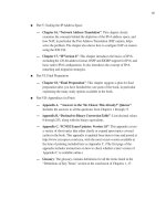
2. Thumb State Register Set
The register set of the Thumb stream is a subset of the register set of ARM stream. The user can directly use the
8 general registers (R0-R7), PC, SP, LR and CPSP. Each supervisor mode has its own SP, LR and SPSR.
● The R0-R7 in Thumb state is the same as the R0-R7 in ARM state.
● The CPSR and SPSR in Thumb state is the same as CPSR and SPSR in ARM state.
Embedded Systems Development and Labs; The English Edition
94
● The SP in Thumb state is mapped to R13 in ARM state.
● The LR in Thumb state is mapped to R14 in ARM state.
● The PC in Thumb state is mapped to PC (R15) in ARM state.
The relationship between the thumb registers and ARM registers is shown in Figure 3-7.
3. The “as” operation in this Lab.
1) .code[16|32]
The “code” operation is used in selecting the current assembly instruction set. The parameter 16 will select the
Thumb instruction set; the parameter 32 will select the ARM instruction set.
R0
R1
R2
R3
R4
R5
R6
R7
SP
LR
PC
CPSR
SPSR
R0
R1
R2
R3
R4
R5
R6
R7
R8
R9
R10
R11
R12
SP£¨R13£©
LR(R14)
PC(R15)
CPSR
SPSR
High Reg
Thumb State
ARM State
Low Reg
Figure 3-7 Register State Diagram
Syntax Format:
.code [16|32]
2) .thumb
as same as .code 16.
3) .arm
Embedded Systems Development and Labs; The English Edition
95
as ame as .code 32.
4) .align
Alignment method: Add filling bits to make the current address meet the alignment.
Syntax Format:
.align {alignment}{,fill}{,max}
alignment: the alignment method, possibly 2 xxx, default is 4.
fill: contents of filling, default is 0.
max: maximum number of filling bits. If the number of filling bits exceeds the max, the alignment will not
process.
Example:
.align
3.3.5 Operation Steps of Lab 3
3.3.6 Sample Programs
1. Lab A Sample Source Code
.global _start
.text
_start:
.arm /* Subsequent instructions are ARM */
header:
ADR r0, Tstart + 1 /* Processor starts in ARM state, */
BX r0 /* so small ARM code header used */
/* to call Thumb main program. */
NOP
.thumb
Tstart:
MOV r0, #10 /* Set up parameters */
MOV r1, #3
BL doadd /* Call subroutine */
stop:
B stop
doadd:
ADD r0, r0, r1 /* Subroutine code */
MOV pc, lr /* Return from subroutine. */
.end /* Mark end of file */
Embedded Systems Development and Labs; The English Edition
96
2. Lab B Sample Source Code
.global _start
.text
.equ num, 20 /* Set number of words to be copied */
_start:
.arm /* Subsequent instructions are ARM header */
MOV sp, #0x400 /* set up user_mode stack pointer (r13) */
ADR r0, Tstart + 1 /* Processor starts in ARM state, */
BX r0 /* so small ARM code header used */
/* to call Thumb main program. */
.thumb /* Subsequent instructions are Thumb. */
Tstart:
LDR r0, =src /* r0 = pointer to source block */
LDR r1, =dst /* r1 = pointer to destination block */
MOV r2, #num /* r2 = number of words to copy */
blockcopy:
LSR r3,r2, #2 /* number of four word multiples */
BEQ copywords /* less than four words to move? */
PUSH {r4-r7} /* save some working registers */
quadcopy:
LDMIA r0!, {r4-r7} /* load 4 words from the source */
STMIA r1!, {r4-r7} /* and put them at the destination */
SUB r3, #1 /* decrement the counter */
BNE quadcopy /* copy more */
POP {r4-r7} /* don't need these now - restore originals */
copywords:
MOV r3, #3 /* bottom two bits represent number */
AND r2, r3 /* of odd words left to copy */
BEQ stop /* No words left to copy ? */
wordcopy:
LDMIA r0!, {r3} /* a word from the source */
STMIA r1!, {r3} /* store a word to the destination */
SUB r2, #1 /* decrement the counter */
BNE wordcopy /* copy more */
Embedded Systems Development and Labs; The English Edition
97
stop:
B stop
.align
src:
.long 1,2,3,4,5,6,7,8,1,2,3,4,5,6,7,8,1,2,3,4
dst:
.long 0,0,0,0,0,0,0,0,0,0,0,0,0,0,0,0,0,0,0,0
.end
3.3.7 Exercises
Write a program; switch the state processor from ARM state to Thumb state. In ARM state, put the value
0x12345678 to R2; in Thumb state, put the value 0x87654321 to R2. Watch and record the value of CPSR and
SPSR. Analyze each of the flag bits.
3.4 ARM State Mode Labs
3.4.1 Purpose
● Learn how to change ARM state mode by using MRS/MMSR instruction. Watching the registers in
different mode and get a better understanding of the CPU architecture.
● Learn how to specify a start address of the text segment by using command line in ld.
3.4.2 Lab Equipment
● Hardware: PC
● Software: Embest IDE 2003, Windows 98/2000/NT/XP.
3.4.3 Content of the Lab
Through ARM instructions, switch the processor mode and watch the behavior of the registers in different
modes. Master the different ARM mode entry and exit.
3.4.4 Principles of the Lab
1. ARM Processor Modes
Most programs operate in user mode. However, ARM has other privileged operating modes which are used to
handle exceptions and supervisor calls (which are sometimes called software interrupts). The current operating
mode is defined by the bottom five bits of the CPSR. The interpretation of these modes is summarized in Table
3-2. Where the register set is not the user registers, the relevant shaded registers shown below replace the
corresponding user registers and the current SPSR (Saved Program Status Register) also become accessible.
The privileged modes can only be entered through controlled mechanisms; with suitable memory protection
Embedded Systems Development and Labs; The English Edition
98
they allow a fully protected operating system to be built. Most ARMs are used in embedded systems where such
protection is inappropriate, but the privileged modes can still be used to give a weaker level of protection that is
useful for trapping errant software.
Processor Modes Explanation
User usr Normal user code
FIQ fiq Processing fast instructions
IRQ irq Processing standard instructions
SVC svc Processing software interrupts
Abort abt Processing memory faults
Undefined und Handling undefined instruction traps
System sys Running privileged OS tasks
Table 3-2 Processor Modes
The mode can be changed through software. Interrupts and exceptions can also change the mode of the
processor. When the processor is working in the user mode, the executing program can’t use some of the system
resources that are protected. In the privileged modes, the system resources can be freely used and the modes can
be changed as well. 5 of these modes are called exception modes:
FIQ (Fast Interrupt reQuest);
IRQ (Interrupt ReQuest);
Management (Supervisor);
Abort (Abort);
Undefined (undefined);
When a specific exception happens, the processor enters the related mode. Each mode has its own additional
registers to avoid the user mode to enter in some unstable state when the exception happens.
The supervisor mode is only available for the higher versions of ARM system architecture. The processor can’t
enter this mode by any exceptions. The supervisor mode has the same registers as the user mode. It is not limited
as the user mode because it is an authorized mode. It is used by the operation system task when the operation
system needs to use the system’s resources without using the same registers that the exception mode used. The
task states will be stable when the additional registers are not used when exceptions happen.
2. Program Status Register
Embedded Systems Development and Labs; The English Edition
99
The program status register CPSR and SPAR in 3.2.4 includes condition code flags, interrupt disable bit, current
processor mode bits, etc. Each exception mode has a Saved Program Status Registers (SPSR). When exceptions
happen, SPSR is used to save the status of CPSR.
The format of CPSR and SPSR is as following:
1) Condition Code Flags
The N, Z, C and V bits are the condition code flags that most of ARM instruction can be detected. These flags
can be used to decide how to execute the programs.
2) Control Bits
The bottom 8 bits I, F, T, M, M, M, M, M are used as control bits. When exception happens, the control bits can
be changed; when the processor working at the supervisor mode, these bits can be changed by software.
● Interruption disable bit: The I and F bits are the interrupt disable bits. When set, these disable the IRQ and
FIQ interrupts respectivel
y.
●
The T bit: This reflects the operating state. When this bit is set, the processor is executing in THUMB state,
otherwise it is executing in ARM state. The instructions that can switch the states between ARM and
Thumb can be used freely.
● Mode Bits: The M4, M3, M2, M1 and M0 bits (M [4:0]) are the mode bits. These determine the processor’s
operating mode, as shown in Table 3-3.
Embedded Systems Development and Labs; The English Edition
100
Table 3-3 ARM Work Modes M [4:0]
3) Other Bits
The other bits of status register are reserved for extension in the future.
3. The Command Line Parameters of ld Used in This Lab
-Ttext org
The “org” is used as the start address of the text segment. Org must be a hex number.
3.4.5 Operation Steps of the Lab
1) Refer to Step 1 of 3.1.5 Lab A, create a new project and name it as ARMMode.
2) Refer to Step 2 of 3.1.5 Lab A, and the sample source file, input the source code of the Lab. After the edition
finished, save the file as ARMMode.s
3) Select Project->Add To Project Files item, or right click the project management window and select the same
item. A dialog will open. Select the source file that has just been created.
4) Refer to Step 2 of 3.1.5 Lab A, finish the related settings.
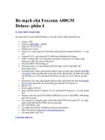
Note: At the Link Option in the Linker page, manually add “-Ttext 0x0” that specifies the start address of the
data segment. This is shown in Figure 3-8.
5) Refer to Step 5 of 3.1.5 Lab A, generate the object code.
6) In the Download Address, the download address should be the same as the start address at the Linker page.
7) Select Debug->Remote Connection to connect the software emulator. Execute the download command; open
the register window.
8) Single step execute the program. Watch and record how the value changes in R0 and CPSR and in the 36
registers after the value is written. Specially notice the value changes in of R13 and R14 in every mode.
Embedded Systems Development and Labs; The English Edition
101
Figure 3-8 Embest IDE Linker Settings
Figure 3-9 Embest IDE Debug Settings
9) Combined with the contents of the Lab and related technology materials, watch the program run. Get a deeper
Embedded Systems Development and Labs; The English Edition
102
understanding of the usage of the registers in different modes.
10) After understanding and mastering the lab, finish the Lab exercises.
3.4.6 Sample Programs of the Lab
.global _start
.text
_start:
# Setup interrupt / exception vectors
B Reset_Handler
Undefined_Handler:
B Undefined_Handler
B SWI_Handler
Prefetch_Handler:
B Prefetch_Handler
Abort_Handler:
B Abort_Handler
NOP /* Reserved vector */
IRQ_Handler:
B IRQ_Handler
FIQ_Handler:
B FIQ_Handler
SWI_Handler:
mov pc, lr
Reset_Handler:
#into System mode
MRS R0,CPSR
BIC R0,R0,#0x1F
ORR R0,R0,#0x1F
MSR CPSR,R0
MOV R0, #1
MOV R1, #2
MOV R2, #3
MOV R3, #4
MOV R4, #5
MOV R5, #6
MOV R6, #7
MOV R7, #8
Embedded Systems Development and Labs; The English Edition
103
MOV R8, #9
MOV R9, #10
MOV R10, #11
MOV R11, #12
MOV R12, #13
MOV R13, #14
MOV R14, #15
#into FIQ mode
MRS R0,CPSR
BIC R0,R0,#0x1F
ORR R0,R0,#0x11
MSR CPSR,R0
MOV R8, #16
MOV R9, #17
MOV R10, #18
MOV R11, #19
MOV R12, #20
MOV R13, #21
MOV R14, #22
#into SVC mode
MRS R0,CPSR
BIC R0,R0,#0x1F
ORR R0,R0,#0x13
MSR CPSR,R0
MOV R13, #23
MOV R14, #24
#into Abort mode
MRS R0,CPSR
BIC R0,R0,#0x1F
ORR R0,R0,#0x17
MSR CPSR,R0
MOV R13, #25
MOV R14, #26
#into IRQ mode
MRS R0,CPSR
BIC R0,R0,#0x1F
ORR R0,R0,#0x12
MSR CPSR,R0
MOV R13, #27
MOV R14, #28
Embedded Systems Development and Labs; The English Edition
104
#into UNDEF mode
MRS R0,CPSR
BIC R0,R0,#0x1F
ORR R0,R0,#0x1b
MSR CPSR,R0
MOV R13, #29
MOV R14, #30
B Reset_Handler
.end
3.4.7 Exercises
Refer to the example of this Lab, change the system mode to user mode; compile and debug the program; watch
the result of the program execution.
Prompt: You can’t switch the mode directly from user mode to system mode. Use SWI instruction to switch to
supervisor mode first.
3.5 C Language Program Lab 1
3.5.1 Purpose
● Learn how to write and debug simple C language program using Embest IDE.
● Learn how to write and use command script files.
● Analyze the result through the Memory, Register, Watch and Variable windows.
3.5.2 Lab Equipment
● Hardware: PC
● Software: Embest IDE 2003, Windows 98/2000/NT/XP.
3.5.3 Content of the Lab
Use the command script to initialize the stack pointer. Use C language to create a delay function.
3.5.4 Principles of the Lab
1. Command Script
When the user connects the IDE to the target board for debugging or execution of programs sometimes the user
needs to perform automatically some specific functions such as reset the target board, clear the watch dog, mask
the interrupt register and memory, etc. By executing a series of commands we can perform various specific
functions. The file that contains a group of sequential commands is called command script file (Embest uses .cs
as the file extension for a command script file).
Each command has a name and appropriate parameters. In each command line the “;” indicates the beginning of
Embedded Systems Development and Labs; The English Edition
105
the comment. Every command that can be used in the debug window can also be used in the command script file
including the executing command SCRIPT. For the debug commands and detailed contents, please refer to
“Debug Command List” in the user guide document UserGuide.chm found on the CD that accompanies the
EmbestIDE ARM development system.
The commands in the script will be executed automatically in a sequential order.
2. The Executing Methods of the Command Scripts
There are two methods of executing a command script:
● Input the SCRIPT command in the command window:
script <command script file name>
● On the Debug page of Project Settings Dialog, specify the command script file at the “Action After
Connected”. The IDE will first execute the command script file after the connection established.
3. The Often Used Commands
1) GO – Execute target program
syntax: go
description: Execute target program from current program counter
Parameter: none
option: none
example: Go
2) MEMWRITE –Write to memory
syntax: memwrite [option] address value
description: Write value to the specified memory location. It accesses the
memory by default in word format using Little Endian mode.
parameter: address memory location
value Specifies value to write.
option: -h Specifies access the memory in half word format.
-b Specifies access the memory in byte format.
-e Write memory using Big Endian mode
example: Memwrite 0x1000 0x5A Write 0x5a to 0x1000
memwrite -e
0x2000000
0x22334455
Equal to memwrite 0x2000000
0x55443322
Embedded Systems Development and Labs; The English Edition
106
3) REFRESH – refresh all windows
syntax: refresh
description: refresh all windows include register, memory, stack, watch,
global/local
parameter: none
option: none
example: refresh
4) REGWRITE – set register
syntax: Regwrite register name value
description: Set register
parameter: register
name
Specifies register name
value The value to write
option: none
example: regwrite pc 0x3840 Set PC with the value 0x3840
5) RESET –Reset the target
syntax: reset
description: Reset the target device
parameter: none
option: none
example: reset
6) STOP –Stop the target
syntax: stop
description: Stop the target
parameter: none
option: none
Embedded Systems Development and Labs; The English Edition
107
example: stop
3.5.5 Operation Steps
1) Refer to the former Labs and create a new project (project name is c1).
2) Refer to the sample program, edit the source file c1.c and c1.cs and add them to the project. Add the c1.cs to
the root directory of the project.
3) Refer to the former Labs, finish the standard settings. One thing to be noted is that the command script file
needs to be added as well in the settings. This is shown in Figure 3-10.
Figure 3-10 Embest IDE Debug Settings
4) Refer to the former Labs and compile the program.
5) Download the program and open the Memory/Register/Watch/Variable windows. Single step through the
program and analyze the results through the Memory/Register/Watch/Variable windows. In the Watch window,
input the variable I and J that need to be watched.
6) Refer to the contents of the Lab and related technology materials, watch the program run.
7) After understanding and mastering the Lab, do the exercises.
3.5.6 Sample Programs
1. c1.c sample program source code
Embedded Systems Development and Labs; The English Edition
108
2. c1.cs sample source code
stop ; stop target CPU
regwrite sp 0x1000 ; initialize stack, set stack pointer at 0x1000
3.5.7 Exercises
Write an assembly program. Use B or BL instruction to jump to the main () function of the C language program.
Use the ev40boot.cs as command script file. Watch the memory settings by executing this command script file.
3.6 C Language Program Lab 2
3.6.1 Purpose
● Create a complete ARM project including boot code, linker script, etc.
Embedded Systems Development and Labs; The English Edition
109
● Understand the boot process of ARM7. Learn how to write simple C language programs and assembly
language boot program.
● Master the linker commands.
● Learn how to specify a code entry address and entry point.
● Learn the usage of Memory/Register/Watch/Variable windows.
3.6.2 Lab Equipment
● Hardware: PC
● Software: Embest IDE 2003, Windows 98/2000/NT/XP.
3.6.3 Content of the Lab
Write a delay function using C language. Use embedded assembly code.
3.6.4 Principles of the Lab
1. ARM Exception Vector Table
An exception takes place when the normal program execution flow is interrupted. For example, the process of
an external interrupt causes an exception. Before the processor core processes the exceptions, the current status
must be preserved. When the exception process is finished, the processor will return to the interrupted program.
The ARM exception Vector Table is shown in Table 3-4.
Table 3-4 ARM Exception Vector table
Vector Address Exception Mode
0x00000000
Reset
SVC
0x00000004 Undefined Instruction UND
0x00000008 Software interrupt SVC
0x0000000C Prefetch abort Abort
0x00000010 Data abort Abort
0x00000014 Reserved Reserved
0x00000018 IRQ IRQ
0x0000001C FIQ FIQ
Multiple exceptions can arise at the same time. As a result, a priority order in which the exceptions are handled
is defined:
High Priorities
1—Reset (highest priority)
2— Data abort
3—FIQ
4—IRQ
5—Prefetch Abort
6— SWI, undefined instruction (including absent coprocessor); this is the lowest priority
These are mutually exclusive instruction encodings and therefore cannot occur simultaneously. Reset starts the
Embedded Systems Development and Labs; The English Edition
110
processor from a known state and renders all other pending exceptions irrelevant. The most complex scenario is
where a FIQ, an IRQ and a third exception (which is not Reset) happen simultaneously. FIQ has higher priority
than IRQ and also masks it out, so the IRQ will be ignored until the FIQ handler explicitly enables IRQ or
returns to the user code. If the third exception is a data abort, the processor will enter the data abort handler and
then immediately enter the FIQ handler, since data abort entry does not mask FIQs out. The data abort is
remembered in the return path and will be processed when the FIQ handler returns. If the third exception is not a
data abort, the FIQ will be entered immediately. When the FIQ and IRQ have both completed, the program
returns to the instruction which generated the third exception, and in all the remaining cases the exception will
recur and be handled accordingly.
From the above, the reset entry is the start point of all the programs. So the first executed line of the program
will be executed at 0x00000000. Generally, the following code is used:
# Setup interrupt / exception vectors
B Reset_Handler
Undefined_Handler:
B Undefined_Handler
SWI_Handler:
B SWI_Handler
Prefetch_Handler:
B Prefetch_Handler
Abort_Handler:
B Abort_Handler
NOP /* Reserved vector */
IRQ_Handler:
B IRQ_Handler
FIQ_Handler:
B FIQ_Handler
Reset_Handler:
LDR sp, =0x00002000
…
2. Linker Script
The Linker Script controls all the linking process. The Linker Script is written using the so called link command
language. The main functions of the linker scripts control how to place the programs to the output file and
control how to locate the output file in the memory. If needed, the linker script can implement other functions.
Most of the linker script files are simple. The simplest linker file has only one command line called SECTIONS.
The SECTION command controls the memory distribution of the output file (code).
SECTION command is powerful. For example, consider a program that consists of consists of code, initialized
data and un-initialized data are placed in “.text”, “.data” and “.bss” sections. The code of these sections needs to
be placed at addresses 0x10000 and 0x8000000, respectively. A simple linker script that performs the above
Embedded Systems Development and Labs; The English Edition
111
tasks is:
SECTIONS
{
. = 0x1000;
.text : { *(.text) }
. =0x8000000
.data : { *(.data) }
.bss : { *(.bss) }
}
The starts with the key word SECTIONS. Next is the body of the command encompassed by “{“ and “}”.
Within the command The first line inside the SECTIONS command sets the value of the special symbol “.”
which is the location counter. If you do not specify the address of an output section in some other way (other
ways are described later), the address is set from the current value of the location counter. The location counter
is then incremented by the size of the output section. At the start of the SECTIONS command, the location
counter has the value 0.
The second line defines an output section “.text”. The colon “:” is required syntax that may be ignored for now.
Within the brackets after the output section name, you list the names of the input section that should be placed
into this output section. The “*” is a wildcard which matches any file name. The expression *(.text) means
all .text input sections of all input files. Since the location counter is 0x10000 when the output section .text is
defined, the linker will set the address of the .text section in the output file to be 0x10000.
The remaining lines define the .data and .bss section in the output file. The linker will place the .data output
section at address 0x8000000. After the linker places the .data output section, the value of the location counter
will be 0x8000000 plus the size of the .data output section. The effect is that the linker will place the .bss output
section immediately after the .data output section in memory.
The linker will ensure that each output section has the required alignment, by increasing the location counter if
necessary. In this example, the specified addresses for the .text and .data section will probably satisfy any
alignment constraints, but the linker may have to create a small gap between the .data and .bss sections.
3. Embedded Assembly Code
The GCC support most of the basic assembly code. The following example shows how the assembly code can
be embedded in a C program. An assembly language notation will be inserted to the output stream when the
compiler meets this statement.
Example: A basic embedded assembly code.
__asm__(“mov r1, r2”)
3.6.5 Operation Steps
1) Refer to the former Labs and create a new project named c2.
2) Edit the new source files c2.c, init.s and script file ldscript. Add them to the project.
3) Refer to the former Labs and finish the standard settings. Note: In the Linker page shown in Figure 3-11 the
ldscript file is used. For the functions of this file please refer to Section 3.6.1.
Embedded Systems Development and Labs; The English Edition
112
Figure 3-11 Embest IDE Linker Script File Settings
Because the concept of initialization file in introduced, the entry file init.o should be specified as shown in
Figure 3-12. Please note that the init.o code must be downloaded at address 0x0. The other programs of the
project will be automatically downloaded to consecutive address locations. The init.s program initializes the SP
register (VERY IMPORTANT !!!) and jumps to the _main () function of the C program.
4) Refer to the former Labs and compile the project. Set the Linker page options as explained in Chapter 2. Also,
Figures 3-12a to 3-12d show the correct settings for this project. Build the c2 project. Set the debug options.
5) Download the program, open the Memory/Register/Watch/Variable windows, single step execute the
program and analyze the results. In the Watch window, input the variable I that need to be watched. Specially
watch and record the changes of the variable I.
6) Combined with the contents of the Lab and related technology materials, watch the program run. Get a deeper
understanding of the usage of the registers in different modes.
7) After understanding and mastering the lab, finish the Lab exercises.
Embedded Systems Development and Labs; The English Edition
113
Figure 3-12 Embest IDE Linker Settings
Figure 3-12a. Remote page setting (first step).