The petrographic microscope
Bạn đang xem bản rút gọn của tài liệu. Xem và tải ngay bản đầy đủ của tài liệu tại đây (679.33 KB, 19 trang )
The petrographic microscope
A petrographic microscope is used to observe a series of characteristics in a mineral
which reflect its properties and allow us to identify it.
The petrographic microscope is a compound microscope which can work with plane
polarised light, meaning that it has some peculiarities.
This is always done with transmitted plane polarised light, meaning that the polariser
must be inserted.
The type of illumination varies according to the feature to be studied, and may be
orthoscopic (parallel, without the condenser) or conoscopic (convergent, with the
condenser incorporated).
The size of minerals that allows for optical identification is not samaller than 0.010
mm. Identification of cryptocrystalline and amorpous materials can be achieved using
submicroscopic techniques such as a scanning electron microscope.
Click on the button showing the feature you require:
Stand
This is the physical support to the other elements of the microscope.
Attached to it are the mechanisms which move the stage and focus the sample.
Other accessories are also joined to it by the same bracket as the stage, such as the
condenser and the polariser.
Illumination system(Hệ thông chiếu sáng)
This is in the base of the stand at the foot of the microscope. In research microscopes,
it is made up of a Light source (1), a set of Lenses (2) which allow a parallel beam of
light to be obtained to avoid the loss of intensity by dispersion, an anti-thermic filter
(3) which prevents the other elements from overheating, a set of chromatic filters (4)
which allow the chromatic characteristics of the light to be modified, a mirror (5) to
orient the light beam in the correct direction and an iris diaphragm (6) to regulate the
light intensity and breadth of the beam.
Polariser( Kính phân cực)
This is situated immediately above the illumination system and below the condenser,
although it is connected to the stage and the condenser by the same upright bracket.
Its function is to convert the natural light from the illumination system into plane
polarised light.
The plane of vibration of the light in the polariser can be turned in some kinds of
microscopes but in normal working conditions it is always fixed at 0°, often
coinciding with what could be called the "East-West" direction.
The polariser is always positioned in the pathways of the light rays for the study of
any optical property.
Polarised light is produced by the polariser and analyser, both of which in modern
microscopes consist of a sheet of plastic (polaroid) which absobs all light except that
vibrating in one direction. Older microscopes employed an ingeneous combination of
calcite prism to produce polarised light (described first by W. Nicol and known as
Nicol prisms).
Condenser(Tụ sáng)
Situated between the polariser and the object, it has a removable lens (1) in such a
way that when it is fitted in the "ON" position it makes the light rays converge onto
the thin section placed on the stage of the microscope. In this situation one speaks of
convergent light or, more normally, conoscopic illumination.
By contrast, when the convergent light lens is in the "OFF" position, the light rays no
longer incide convergently but rather folow an approximately parallel path and all of
them incide perpendicularly on the slide. In this situation one speaks of parallel light
or, to be more correct, orthoscopic illumination.
An iris diaphragm allows the illuminated area to be varied (known as the aperture
diaphragm). For observing relief and Becke line it is usually necessary to partially
close this diaphragm.
Stage(Bàn soi)
This serves as a support to the thin section (1) which is to be studied. It may be
heightened or lowered (2) to allow the object to be focussed.
It is round and can be rotated on a vertical axis which passes through its centre.
It is graduated and on the outside it has a fixed goniometer (3) which allows the value
of the angles turned to be measured accurately.
Objetives
These are the lens used for magnifying the specimen on the stage. Four or five are
normally supplied (x4, x10, x25, x50).
This allows a real and inverted image to be obtained of the object under examination.
It lets the polarised light pass through without affecting the polarisation plane.
Objectives are often mounted on a revolving objective holder (1), which allows
quick and easy change of magnification.
When the stage is rotated, the axis of rotation should coincide with the centre of the
field of view (the axis of the microscope). This is achieved on some microscopes by
adjusting a collar on the barrel of each objective (2)
To centre a microscope, the point about which an object is seen to rotate when the
stage is rotated must be brought to the centre of the cross-hairs by adjusting the
centring screws.
Focus
El enfoque de la imagen en el microscopio se realiza separando el objeto a estudiar de
los objetivos. Mediante unos anillos (1 y 2) se puede subir y bajar la platina para
buscar el foco (en los microscopios antiguos la platina permanece fija, siendo los
objetivos los que se desplazan). En este microscopio existe un amilla "macro" de
desplazamiento brusco (1), para aproximar el enfoque, y uno, llamado "micro" (2),
para ajustarlo.
La operación de enfoque requiere seguir unos determinados pasos para realizarla con
seguridad. El procedimiento correcto es el siguiente. Mirando por fuera del
microscopio se lleva el objetivo junto a la preparación y mirando luego por el ocular
se va separando lentamente hasta obtener la imagen. Si se busca el enfoque acercando
el objetivo a la preparación se corre el riego de producir fracturas (en la preparación o,
en lo que es mucho peor, en la lente frontal del objetivo) si nos pasamos del plano de
foco.
Slot for inserting compensators
This is immediately below the analyser and its greatest dimension forms an angle of
45º with the direction of vibration of the Nicols (polariser and analyser).
The main directions of vibration of the compensating plate and those of the polariser
and analyser are situated at 45°.
Compensators(Bù màu)
These are plates of anisotropic substances, whose planes of vibration coincide with
their two dimensions, length and width.
Accessory plates consist of mineral sections of a thickness such that they produce a
known amount of retardation.
They may be wedge-shaped so that retardation (and thus colour) will depend on the
thickness acting at any moment in time.
The effects that these compensators introduce are superimposed on the effects that the
minerals on the microscope stage introduce.
They are used for studying interference figures and the retardation produced by
mineral specimens.
When required, they are inserted into the microscope tube in a slot between the
objetives and the analyser.
Analyser(Phân tích)
This is above the objective, and is made up of a polarising plate, whose height may
be adjusted at will, using a graduated dial (1).
Unlike the polariser, the analyser does not always have a part to play in the passage of
the light rays and can be installed or removed at will. It is used to study certain
properties but is not necesary for others.
The polarising plane is generally N-S, and it is always perpendicular to the polariser,
such that if there is no object in the way, no light passes and Extinction occurs.
Below it is a slot where compensating plates can be inserted.
When only the polariser (1) is being used, a normal image is observed, but when the
analyser is in place (2), an extinction of light occurs.
If an anisotropic substance is in the light's path, the light splits into two rays which
vibrate perpendicularly and do not necessarily coincide with the directions of the
polariser or analyser. When these rays reach the analyser, two components come into
being which vibrate, one on the plane of the analyser and the other on a perpendicular
one. The former is responsible for the grain being seen, whilst the latter is annulled. A
false colour appears, known as an interference colour (3).
Amici Bertrand lens
This is found immediately below the ocular. It may be incorporated (1) or removed (2) at will. It
can only be used when convergent light is used to observe the property called the Interference
figure (3).
The Bertrand lens magnifies and focusses interference figures but the Bertrand lens does not
produce the interference figure but modifies the focal plane of the image formed by the objective
to allow it to be focussed and amplified by the ocular.
An alternative means of viewing interference figures is to remove the eyepiece and look down
the microscope tube at the highe-power objetive lens, preferably wiyh the aid of a pin-hole stop
inserted at the top of the tube.
Eyepieces(Thị kính)
This is a system of lenses fitted to the top of the microscope and whose function is to
form a virtual and amplified image from the real image created by the objective.
The eyepiece assembly contains two cross-hairs, and is slotted into the microscope
tube so that the cross-hairs are orientated E-W and N-S, i.e. parallel to the vibration
directions of the polariser and analyser.
Most eyepieces have a magnification of x8 or x10.
The focal plane of the new image is about 25cm from the upper lens, the normal
distance of vision of the human eye.
Thin sections
In order to observe a sample it is necessary to previously prepare it. The method
depends on whether we are dealing with a coherent material (rock) or a loose material
(soil and sand).
Preparation of a rock
Cut.
The first step is to cut the original rock in order to obtain a fragment with a flat
surface similar in size to that of the preparation which we require.
Polish
Once the flat surface is achieved, it must be polished to remove the roughness of the
cut and make it as smooth as possible.
Cementation
After the surface has been polished, it is cemented onto a glass slide with resin or
Canada Balsam.
Cut
It is then recut, trying to make the second face parallel to the first and as thin as
possible.
Lapping
Next, the sample is lapped until it is only 50µm thick, so that with a final polish its
thickness is between 20 and 30µm.
Cover
The last stage is to cement a cover glass on top with the same material used as before,
trying to ensure that no air bubbles remain trapped in between.
Preparation of a soil
In order to obtain microscopic preparations of soils, it is necessary to give coherence
to the soil samples so that they can be cut, lapped and polished.
In order to achieve the hardness required, the soil samples are vacuum packed in
liquid polyester resin.
The resins harden as they polymerise, thus producing blocks which include the soil
sample and conserve its natural structure unchanged. These blocks can now be treated
as if they were rock samples.
Preparation of sands
The way to prepare sands differs according to their grain-size.
Fine sands
For sizes smaller than 200µm, which are known as fine sands, this can be done
directly.
Coarse sands (>200 µm)
In this cases it is necessary to place them in a resin and follow a similar procedure to
that of a rock (2), .
Las arenas gruesas tienen un tamaño (>200 micras) que las hace opacas si se montan
directamente (1), por lo que es necesario incluirlas en una resina para darle
coherencia. Para ello se colocan en un pequeño recipiente de fondo plano y se
incluyen al vacio como se hace con las muestras de suelos (2).
Oscillating theory of the light
Light is a form of radiant energy, and although its precise nature involves very
complex Physics theories, all the phenomena relating to minerals can be explained by
exclusively considering the oscillating theory, i.e. for our purposes, light is
propagated as a consequence of a vibration of particles.
In the figure, a light wave is represented in diagram form along a rectilinear path that
includes the state of vibration of the different points, successively reaching different
displacements, from a state of rest. The result of this vibration of adjacent points is the
propagation of the wave.
We therefore have a very important point and one that we must keep in mind: that is,
the directions of vibration and of propagation are perpendicular. This is strictly
true for all isotropic media, although in certain anisotropic ones the angle may be
different from 90°. However, for our purposes we can always consider them as
perpendicular (such an assumption simplifies the explanations without detracting from
the essential principles).
We shall now review some very simple concepts relating to this oscillating
phenomenon.
Wave
This is a sinusoidal movement caused by the group of vibrating particles.
Ray
This is the rectilinear path followed by the wave (the path followed by the light).
Wave length
This is the distance between two points in phase with each other, which are those
which are vibrating in the same manner, are at an equal distance from the state of rest
and move in the same direction.
The different wave lengths are translated by the human eye into different colours:
violet = 410 mµ yellow = 580 mµ
blue = 480 mµ orange = 620 mµ
green = 530 mµ red = 710 mµ
Frecuency
This is the number of wave oscillations per second, which gives the wave velocity.
The part of the wave between two points in phase is called oscillation.
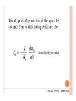
Velocity of propagation
This is a characteristic of the medium in which light is propagated, and is determined
by the Refractive index (n), or the relation between the velocity of propagation in a
vacuum (c) and in the medium under consideration (v).
n=c/v
For this reason, the "n" of minerals is always greater than one (ranges from 1.43 to
3.22). The index of refraction of a vacuum is one, and it is considered the same for air
as well.
The velocity and the refractive index are inverse (a high velocity corresponds to a low
index).
In anisotropic mediums, as in most minerals, velocity (and thus "n" as well) varies
with direction.
Natural light and plane polarised light
Natural light (from the sun) vibrates in all directions in space (infinite directions of
vibration), and its axis is defined by the ray (which we shall consider as being
perpendicular to all directions of vibration and coinciding with the direction of light
propagation).
Polarised light vibrates in a single plane at any one moment in time, but the direction
of the plane of vibration changes with time. When it always vibrates on the same
plane, it is called plane polarised light (which we shall simply call polarised light).