BS 5588 4 1978 fire precautions in the design and construction of buildings—MVAC
Bạn đang xem bản rút gọn của tài liệu. Xem và tải ngay bản đầy đủ của tài liệu tại đây (904.22 KB, 46 trang )
BRITISH STANDARD
BS 5588-4:
1978
(Reprinted,
incorporating
Amendment No. 1)
Fire precautions in the
design and
construction of
buildings —
Part 4: Code of practice for smoke
control in protected escape routes using
pressurization
UDC 614.841.334:699.815:721.052.2
Licensed copy:RMJM, 29/08/2005, Uncontrolled Copy, © BSI
BS 5588-4:1978
This British Standard, having
been prepared under the
direction of the Codes of Practice
Committee for Building was
published under the authority
of the Executive Board on
30 June 1978
© BSI 01-1999
The following BSI references
relate to the work on this
standard:
Committee reference FSM/14
Draft for comment 76/12178 DC
ISBN 0 580 10260 2
Code drafting committee BLCP/24
Precautions against fire
Most of the work on this code was undertaken while the reference number of
the responsible committee was BLCP/24. The reference number was changed
to FSB/14 in December 1977, but the member ship was not altered because of
the change in committee reference.
Former members
Committee Chairman P G Robinson Health and Safety
Executive
HM Senior
Chemical
Inspector of
Factories
Fire Advisor
Association of Metropolitan
Authorities I Riley
British Fire Services’
Association C G Durrant
British Gas Corporation K J D Brady Home Office P G Robinson
Chief and Assistant Chief Fire
Officers Association G Karran
Incorporated Association of
Architects and Surveyors P Mitchell
Concrete Society Limited R D Anchor D J Edge
Consumers’ Standards Advisory
Committee of BSI Mrs C Davis OBE
Institute of Building
Control
A R Oxley
E P Cavanaugh Institution of Fire
Engineers
I J Reader
Department of Education and
Science D H Griffin
Institution of Gas
Engineers K J D Brady
Department of Health and
SocialSecurity R D Gajjar
Institution of Structural
Engineers J M Brighton
Department of the Environment
(PSA)
K Elvin D E Steadman
D Andrews Multiple Shops Federation J E Aitken
Department of the Environment,
Building Research
Establishment, Fire Research
Station G M E Cooke
National Coal Board Dr W G Kaye
A J M Heselden National Council of
Building Materials
Producers P Jackman
Department of the Environment,
Housing and Construction A P Roach
Royal Institute of British
Architects A C Parnell
Electricity Supply Industry in
England and Wales G R Galaway
Royal Institution of
Chartered Surveyors A Solomons
Fire Insurers Research and
Testing Organization R W Pickard
T D Hogg
Fire Offices’ Committee G C Ackroyd Scottish Development
Department M R Miller
Fire Protection Association R W Fisher
Greater London Council K A Cockman
M J Doherty
Chief and Assistant Chief Fire
Officers’ Association R T Ford
Fire Protection Association The Director
Consumer Standards Advisory
Committee of BSI J C Maxwell OBE
Institution of Structural
Engineers J C M Forrest
T N Watkins OBE National Council of Building
Material Producers N M Chaldecott
Amendments issued since publication
Amd. No. Date of issue Comments
5377 September
1986
Indicated by a sideline in the margin
Licensed copy:RMJM, 29/08/2005, Uncontrolled Copy, © BSI
BS 5588-4:1978
© BSI 01-1999
i
Contents
Page
Code Drafting Committee Inside front cover
Foreword ii
1 Scope 1
2 References 1
3 Definitions 1
4 The building 2
5 The system 7
6 The installation and equipment 29
7 General 32
Appendix A A worked example 35
Figure 1 — Pressurizing staircase only 4
Figure 2 — Deleted
Figure 3 — Pressurizing staircase and lift lobby 5
Figure 4 — Leakage paths in series 11
Figure 5 — Leakage paths in parallel 11
Figure 6 — Steps in obtaining the equivalent resistance of a
combination of series and parallel paths of air leakage 12
Figure 7 — Diagram of leakage from lift landing doors 16
Figure 8 — Diagram of airflow conditions listed in Table 8 20
Figure 9 — Diagram of airflow conditions listed in Table 9 21
Figure 10 — Diagram of airflow conditions listed in Table 10 22
Figure 11 — Plan of building for worked example 35
Table 1 — Pressurization levels 9
Table 2 — Values of (P)
1/N
for N = 2 and N = 1.6 10
Table 3 — Typical leakage areas for four types of door 13
Table 4 — Air leakage data for doors 14
Table 5 — Air leakage data for windows 15
Table 6 — Values of factor F for various vent sizes 17
Table 7 — Values of K 18
Table 8 — Airflow through an open door: staircase only
pressurized: staircase/accommodation door open 20
Table 9 — Airflow through an open coor: staircase and lift
lobby pressurized to same level: airflow when one
lobby/accommodation door is open 21
Table 10 — Airflow through two open doors: staircase and
lift lobby pressured to same level: two lobby doors (stairwell/lobby
and lobby/accommodation) open on same floor 22
Table 11 — Minimum total length of window cracks
(per floor) for satisfactory venting of the pressurizing air 27
Table 12 — Suggestions for choice of venting system 28
Publications referred to Inside back cover
Licensed copy:RMJM, 29/08/2005, Uncontrolled Copy, © BSI
BS 5588-4:1978
ii
© BSI 01-1999
Foreword
This new code of practice was prepared under the direction of the Fire Standards
Committee.
In addition to the existing BS 5588-1.1, BS 5588-2, BS 5588-3 and BS 5588-5,
other parts will include new codes for the precautions to be taken in places of
assembly, for means of escape for disabled people, for ventilation and air
conditioning ducts, for enclosed shopping complexes and the revision of
CP 3:Chapter IV-1, which will appear as BS 5588-1.2
This code offers a method for keeping protected escape routes clear of smoke by
pressurizing these routes and so creating a pattern of airflow away from them.
The objects of this code are to state general principles and to give both planning
and technical data concerning pressurization of protected escape routes.
Pressurization is one of several methods of smoke control in buildings in the event
of fire and it is not suggested that it is the only effective method in all
circumstances. It has however certain advantages inasmuch as it offers greater
flexibility of layout than other methods and in some cases reduced costs stemming
from this flexibility.
Designers will need to offer the system described in this code to the building
control authority as an alternative to the natural ventilation that may be
required by specific legislation. Protected escape routes may include corridors,
lobbies, staircases and other communication spaces connecting to a final exit.
Unprotected routes include spaces within rooms or open storeys and corridors
where travel distances apply. The travel distances as specified in other codes or
regulations should not be modified because smoke control is employed as
described in this code.
Once inside a protected route, people in a building should be able to make their
way to a final exit and safety in the open air. It is smoke and toxic gases, rather
than flame, that will in the first instance inhibit this movement and the exclusion
of smoke and gases from the protected routes is thus of great importance.
In normal fire-prevention design the intention always will be to confine the fire
within a fire compartment and, although this may be effective in limiting the
spread of fire, smoke will readily spread to adjacent spaces through the various
leakage openings that occur in the compartment enclosure, such as cracks,
openings around pipes, ducts, airflow grilles and doors. In good building practice
the leakage at some of these points will be minimized but it is not generally
possible to seal them completely.
There are two main factors that determine the movement of smoke arising from
a fire in a building. These are:
a) the mobility of smoke that results from its consisting of hot gases less dense
than the surrounding air;
b) the normal air movement (which may have nothing to do with the fire) that
can carry smoke, sometimes slowly, sometimes quickly, to all parts of the
building.
Air movement is itself controlled by:
a) the stack effect (see 3.1.4);
b) the wind, all buildings having some air leaks and wind action contributing
to air movement through the leaks;
c) any mechanical air-handling system installed in the building.
Licensed copy:RMJM, 29/08/2005, Uncontrolled Copy, © BSI
BS 5588-4:1978
© BSI 01-1999
iii
Pressurization provides pressure differences that oppose and overcome those
generated by the factors causing movement of smoke. In pressurization, air is
injected into the protected escape routes, i.e. into staircases, lobbies or corridors,
to raise their pressure slightly above the pressure in adjacent parts of the
building. Consequently smoke or toxic gases will be unlikely to find their way into
escape routes.
The use of a system to extract air from spaces that are pressurized is very strongly
deprecated because it will render the maintenance of the required pressure in the
escape routes extremely difficult.
It is necessary to determine not only where the fresh air supply for pressurization
is to be introduced into a building but also where that fresh air will leak out and
what paths it will take in the process. The aim will be to establish a pressure
gradient (and thus an airflow pattern) with the protected escape routes at the
highest pressure and the pressure progressively decreasing in areas remote from
the escape routes. The design criteria given in detail in clause 5 deal with the
various ways in which the escape of pressurized air can be arranged.
A pressurization system for smoke control should:
a) give positive smoke control in the protected escape routes;
b) be readily available when a fire starts;
c) be reliable and capable of functioning for a period corresponding to the
standard of fire resistance of the elements of structure in a building;
d) be simple and economic.
Some of the advantages that can be expected from the use of pressurization are:
a) staircases and lobbies need not be placed on external walls;
b) smoke shafts may not be required as a means of alternative ventilation;
c) it may be possible to omit some “smoke stop” doors from escape routes;
d) the additional staircase considered necessary in calculating the number of
staircases required in relation to the population density when other methods
of smoke control are used may possibly be omitted;
e) conservation of energy.
Diagrams that accompany the text in this code are intended only to clarify points
made in the text. It should not be assumed that the arrangements shown are
more satisfactory than others that may be devised.
Consultation with the building control authority at an early stage is
recommended, to check not only that proposals for means of escape are
satisfactory but also that other building regulations, concerned for example with
ventilation of parts of the building for public health purposes, are satisfied.
This code does not contain all the necessary information for the satisfactory
design of a pressurization scheme, which should be undertaken by a competent
person.
A British Standard does not purport to include all the necessary provisions of a
contract. Users of British Standards are responsible for their correct application.
Compliance with a British Standard does not of itself confer immunity
from legal obligations.
Summary of pages
This document comprises a front cover, an inside front cover, pages i to iv,
pages1to 38, an inside back cover and a back cover.
This standard has been updated (see copyright date) and may have had
amendments incorporated. This will be indicated in the amendment table on
the inside front cover.
Licensed copy:RMJM, 29/08/2005, Uncontrolled Copy, © BSI
iv
blank
Licensed copy:RMJM, 29/08/2005, Uncontrolled Copy, © BSI
BS5588-4:1978
© BSI 01-1999
1
1 Scope
This code of practice gives guidance on the use of pressurization in buildings for the purpose of smoke
control in protected escape routes.
The code is intended to apply to new buildings, though there is no reason why the principles should not be
used when existing buildings are to be altered or adapted. it is intended initially for application to protected
escape routes in flats and maisonettes, and in offices and shops.
The principles stated in the code may be used for other occupancies and purpose groups where the
fundamental aim is to keep the protected escape route clear of products of combustion.
This code is not intended to apply to shopping malls and town centre redevelopments. Information on these
will be found in HMSO publication “Fire Prevention Guide 1: Fire Precautions in Town Centre
Redevelopments”.
2 References
The titles of the publications referred to in this code are listed on the inside back cover.
3 Definitions
For the purposes of this code, the definitions given in BS 4422, together with the following, apply.
3.1
air duct
a passageway for the transmission of air
3.2
air escape or air venting
the movement of air out of a building through a low-resistance path provided by incidental or specially
provided apertures, the air movement being caused by pressure differences developed in the building
3.3
air leakage
the movement of air, generally from a pressurized space through openings that have relatively small
cross-sectional area
3.4
air supply
a mechanically driven current of air lead by suitable ductwork or impelled by the direct action of a fan
3.5
buoyancy
an upward force exerted on a fluid when it is surrounded by a denser fluid
3.6
leakage area
the cross-sectional area of the air leakage path, measured normally to the direction of airflow and generally
integrated into a total area for a particular building component (such as a door or a window)
3.7
lobby
a space in a building used to separate one part of the building from another part, usually separating a
staircase from the general accommodation
3.8
plenum
a compartment or chamber or space to which one or more air ducts are connected and that forms part of an
air distribution system
3.9
pressure differential
the difference in pressure between two adjacent spaces in a building
Licensed copy:RMJM, 29/08/2005, Uncontrolled Copy, © BSI
BS5588-4:1978
2
© BSI 01-1999
3.10
pressurized space
a space in a building in which the air pressure is maintained at a higher value than that in the rest of the
building by direct input of an air supply
3.11
pressurization
a method of protecting escape routes against the ingress of smoke by maintaining the air within them at
pressures higher than those in adjacent parts of the building
3.12
pressurization level
the pressure difference between the pressurized space and the accommodation served by the pressurized
escape route [expressed in pascals (Pa)]
1)
3.13
simple lobby
a lobby that has no door opening out of it other than a door to a staircase and a door (or doors) leading to
the accommodation
NOTEA lobby that has doors to toilets or doors to lifts is not a simple lobby.
3.14
stack effect
the pressure differential caused by the air inside the building being at a temperature different from that of
the air outside the building, which, when there are openings top and bottom, will promote natural airflow
through the building, upwards when the building air is warmer than the outside air and downwards when
it is cooler
4 The building
4.1 General
4.1.1 General principle of pressurization. The spaces to be pressurized will be those that constitute the
protected escape routes. These are the staircase(s), the lobbies and in some cases the corridors. One or more
of these spaces will be pressurized and the general principle is that smoke control will only be satisfactory
for those spaces that are pressurized, i.e. that have an input of pressurizing air (air supply). Thus the
extent to which smoke encroachment is to be prevented will determine the spaces to be pressurized.
4.1.2 Single-stage or two-stage pressurization. The pressurization system can be designed to operate only
in an emergency. This is called a single-stage system. Alternatively, a continuously operating low level of
pressurization of the appropriate spaces can be incorporated as part of the normal ventilation with
provision for an increased level of pressurization to be brought into operation in an emergency. This is
called a two-stage system. (See5.2.1.)
The two-stage system is generally regarded as preferable because some measure of protection is always
operating and therefore any smoke spread in the early stages of fire will be prevented. However, either
method will be acceptable subject to any special circumstances dealt with in this code.
4.1.3 Combustible material in protected escape routes. It is important that any staircase, lobby or corridor
of a protected escape route should contain or be likely to contain, a minimum of combustible material in
which a fire could occur.
4.2 Methods of pressurizing the spaces to be pressurized
4.2.1 Method 1. Pressurizing staircase(s) only. The protection given by this method is entirely confined to
the vertical part of the escape route. It is only appropriate in buildings where no smoke control is needed
for the horizontal part of the escape route on each floor of the building and, in general, it should be used
only when a staircase is approached directly from the accommodation area or through a simple lobby. By
definition (see 3.13) this lobby should not give access to lifts or other rooms (e.g. toilets) that could
constitute an appreciable leakage path and allow the pressurizing air to bypass its required direction of
flow.
1)
1 Pa = 1 N/m
2
.
Licensed copy:RMJM, 29/08/2005, Uncontrolled Copy, © BSI
BS5588-4:1978
© BSI 01-1999
3
The simple lobby, which may be required to complete the fire-protecting enclosure of the staircase, will
serve to reduce the effect of an open door to the pressurized staircase.
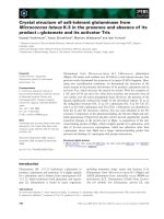
The simple lobby should be unventilated, in which case it will be automatically pressurized by the air
flowing out of the staircase. Figure 1 shows examples of pressurized staircases leading into simple lobbies.
The resulting pressurization of the lobbies is indicated, as also is the effect of an open lobby door.
During a fire emergency all protected staircases interconnected by lobbies, corridors or accommodation
areas should be simultaneously pressurized.
4.2.2 Method 2. Pressurizing the staircase(s) and all or part of the horizontal route
4.2.2.1 General. In every building in which each floor has a horizontal component of the protected escape
route (other than the simple lobby mentioned in4.2.1) the pressurization should be carried into the lobby
and possibly into the corridor beyond.
This arrangement carries the protection right up to the door leading into the accommodation area in which
a fire might occur. Additionally, the effect of an open door on the pressurization levels is largely localized
on the floor concerned.
During a fire emergency all protected staircases and associated lobbies/corridors forming part of the whole
pressurization scheme should be simultaneously pressurized.
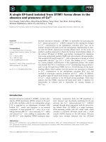
4.2.2.2 Pressurizing staircase and lobby. If a lobby separating the staircase from the accommodation is
other than a simple lobby, this lobby should be pressurized independently of the staircase, i.e. it should
have pressurizing air supplied from a duct (or source) that is separate from that supplying the staircase.
The lobby pressure should be equal to or slightly below the pressure in the staircase (but not more
than5Pa below). Figure 3 shows an example of independently pressurizing staircase and lift lobby and
indicates the effect of an open door.
4.2.2.3 Pressurizing staircase, lobby and corridor. If the lobby opens into a corridor of substantial
construction (i.e. 30min fire resistance or more) that forms part of the protected escape route, the
pressurization may with advantage be extended to include the corridor and so take the smoke control right
up to the door of the accommodation unit, office or flat. To do this an independent air supply should be
provided to the corridor and the pressure should be equal to or slightly below that in the associated lobby,
but not more than5 Pa below.
There are difficulties associated with this extension of the pressurization. If the corridor has many doors
(or other leakage paths) the air supply needed will be large, each door should be self-closing and each
unpressurized space opening onto the corridor should have adequate leakage to the outside air
(asrecommended in 5.5).
4.2.3 Method 3. Pressurizing lobbies and/or corridors only. In some buildings it may be found necessary,
perhaps for constructional reasons (such as difficulty in arranging the required ductwork for independent
pressurization) to allow the staircase to be pressurized by the air that leaks into it from the associated
pressurized lobbies or corridors. If properly designed this can be a satisfactory method but in some cases it
may be found that the total air supply needed for pressurizing the lobbies only may be greater than that
needed if the staircase and lobbies are independently pressurized.
In this method the staircase should not be permanently ventilated except by any opening shown to be
necessary by the calculation for the open-door condition dealt with in 5.3.2.8.
All pressurized lobbies and/or pressurized corridors on all floors in a building should be pressurized in an
emergency.
4.2.4 “Pressurizing” the whole building (not recommended). Designs have been suggested for a scheme in
which pressure differentials are not developed inside the building but air is introduced in such a way that
the whole building is raised to a pressure in excess of that obtaining outside the building. In the event of
fire, airflows are set up in opposition to the smoke flow by opening vents on the fire floor. This system has
been suggested for buildings in which the internal divisions are so leaky that pressurizing particular spaces
(such as staircases or lobbies) is not possible.
In the UK there is no experience with this method and it is suggested that, unless there are over-riding
reasons for its adoption in a special case, it does not constitute a satisfactory method.
To design this type of system the details, including location, of the air leakage from the external wall are
required. If this leakage is appreciable (as suggested by some of the information available), a wastefully
high amount of pressurizing air is required.
Licensed copy:RMJM, 29/08/2005, Uncontrolled Copy, © BSI
BS5588-4:1978
4
© BSI 01-1999
Figure 1 — Pressurizing staircase only
Licensed copy:RMJM, 29/08/2005, Uncontrolled Copy, © BSI
BS5588-4:1978
© BSI 01-1999
5
Figure 2 — Deleted
Figure 3 — Pressurizing staircase and lift lobby
Licensed copy:RMJM, 29/08/2005, Uncontrolled Copy, © BSI
BS5588-4:1978
6
© BSI 01-1999
The effectiveness of a system pressurizing the whole building relies entirely on the opening of venting on
the fire floor only. Venting elsewhere can cause smoke to spread to other parts of the building. In particular,
an open door at the foot of a staircase can cause that staircase to become filled with smoke. Consequently,
if this system is used additional “smoke stop” doors have to be installed. For these reasons the
pressurization of the whole building is not recommended in this code of practice.
4.3 Interaction between several pressurized spaces
4.3.1 General. In a building, particularly a large building, there may be several pressurized spaces. These
may be directly interconnected or they may be separated by a large unpressurized area. The presence of
several pressurized spaces in a building does not generally create a problem.
4.3.2 Directly connected pressurized spaces. This condition will arise when the staircase and the lobby (and
perhaps the corridors) are pressurized. This will apply to many buildings. In such a system the design aim
should be to ensure airflow from the staircase, through the lobby, through the corridor (if appropriate) and
into the accommodation space where a fire might occur.
There is no objection to all the connected pressurized spaces being maintained at the same pressure, which
should be that given in Table 1 for the appropriate building height.
If there is a difference in pressure between adjacent pressurized spaces, this should be small and should
not exceed 5Pa. The pressurized space nearest to the accommodation should always be at the lower
pressure.
This design condition will be disturbed if, for instance, a door on the staircase is opened on to an
unpressurized space. This circumstance may be regarded as a shortlived temporary occurrence during
which the staircase pressure will fall below that of the adjacent lobby, but the lobby pressurization will still
maintain a sufficient airflow towards the possible fire area. A design check is outlined in clause 5 to ensure
that this condition is satisfied.
4.3.3 Pressurized spaces that have no direct connection.This condition arises when a building has two or
more pressurized escape-route systems opening out into the same unpressurized accommodation area.
There are no particular problems or restrictions associated with this arrangement because each
escape-route system should have its own independent pressurizing plant and the unpressurized
accommodation space should have adequate leakage arrangements to allow the pressurizing air from all
the pressurized areas to escape to open air. Provided these conditions are satisfied there will be no
possibility of any interaction between the several pressurized parts of the building.
4.4 Single-staircase or multiple-staircase buildings
4.4.1 The staircases. The factors associated with floor area that determine whether a building may have a
single staircase or needs to have two or more staircases will not be affected by the proposal to use
pressurization in the building, except that a pressurized staircase (with a lobby and/or corridor, as
appropriate) may be considered safer than an escape route that is naturally ventilated.
4.4.2 Restrictions
4.4.2.1 Pressurized and unpressurized staircases in the same building. No restrictions will arise when all
the staircases in a building are pressurized, but the use of pressurized and naturally ventilated staircases
in the same building will introduce difficulties and should be avoided if possible. It should be considered
only if the staircase is cross ventilated and separated from the pressurized staircase(s) by a large
unpressurized undivided space from which the air can escape at points well away from the unpressurized
staircase(s), in order to prevent the unpressurized staircase from becoming filled with smoke.
Under no circumstances should a pressurized staircase be connected by a corridor or lobby to an
unpressurized staircase.
4.4.2.2 Pressurized and unpressurized spaces in the same escape route. Another possibility is a mixed
system for the escape route, for instance a pressurized staircase with a naturally ventilated lobby between
it and the accommodation. In this example the protection afforded by the pressurization will be completely
confined to the staircase. The pressurization will do nothing to keep the naturally ventilated lobby clear of
smoke; it will only provide a steady supply of fresh air to dilute any smoke entering the lobby. This
arrangement is not recommended and the lobby in this position should be unventilated.
Licensed copy:RMJM, 29/08/2005, Uncontrolled Copy, © BSI
BS5588-4:1978
© BSI 01-1999
7
4.5 Relation between emergency pressurization and the normal air conditioning system. It has
been explained that the purpose of a pressurization system is to establish an airflow condition in the
building that will prevent the smoke from a fire moving towards or past the escape route doors. This is
achieved by maintaining the escape routes at an excess pressure by providing them with a mechanically
driven constant supply of fresh air, and, additionally, by providing for this air to leak out of the building at
identified places in or near external walls that are as far as possible from the escape route doors.
It is therefore preferable that the airflow pattern established in the building by the normal air conditioning
system should also be away from the escape route entrance, with the vitiated air being removed for exhaust
or recirculation at points remote from the escape route entrances.
If the pressurization system is two-stage, i.e. has a constant running feature that maintains the escape
routes always at a slight excess pressure, the general air conditioning system to fit in with this
arrangement will probably adopt a satisfactory airflow pattern that is always away from the escape routes.
When the pressurization system is single-stage, i.e.operates in an emergency only, the interaction between
it and the normal air conditioning arrangement may not be so obvious but nevertheless it should be
considered in the overall design concept.
An air conditioning system that uses the corridors or the false ceiling of a corridor as the exhaust plenum
for the vitiated air should not be used in conjunction with a pressurization system unless special
arrangements are made for closing off the whole exhaust system in case of fire.
In any case, an air conditioning system that could encourage smoke to enter the corridors is not favoured
for fire safety reasons even if there is no pressurization in the building.
4.6 Integration of emergency system with normal air conditioning equipment. It is suggested that
the normal air conditioning system and the pressurization system should be treated as an integral whole
when design calculations are carried out. This will certainly be necessary when the pressurization is
two-stage, i.e. a reduced level of pressurization will be operative at all normal times and so the air volumes
and air movement used for it need to be considered in the wider context of the air movements in the normal
ventilation system.
When the emergency pressurization is brought into action the following changes in the normal air
conditioning system should be made.
a) Any recirculation of air should be stopped and all exhaust air vented to atmosphere, e.g. by means of
a suitable damper.
b) Any air supply to the accommodation spaces should be stopped.
c) The exhaust system may be continued, provided:
1) the positions of the extraction grilles are compatible with the need to establish a general airflow
that is not towards the protected escape route entry;
2) the construction of the ductwork and fans is such that it will not be rendered inoperable by hot
gases and smoke;
3) there is no danger of smoke spreading to other floors by the path of the extraction system; to ensure
this the extraction fan has to be kept running and therefore its position and electrical supply have to
be protected.
The signal to initiate all these changes in the operation of the air conditioning system should come from
the same source as that which operates the emergency pressurization.
The use of a smoke detector in the air conditioning ductwork should not be relied on for this purpose
because of the dilution of the smoke that will occur when several floors are served by the same system. This
could cause a delay in operating the necessary adjustment to the air conditioning system in case of fire.
5 The system
5.1 Basic design criteria for designing the system and its component parts
5.1.1 Basic design. The criterion is to establish in the building a pressure gradient pattern that will always
ensure that smoke moves away from the escape route. To do this the escape route is maintained at an
excess pressure and adequate air leakage has to be provided from the accommodation areas.
5.1.2 Pressure differentials. These are established by maintaining a continuous supply of fresh air, fed by
mechanical means into the pressurized space.
Licensed copy:RMJM, 29/08/2005, Uncontrolled Copy, © BSI
BS5588-4:1978
8
© BSI 01-1999
5.1.3 Space being pressurized. This will unavoidably, in any building, have air leakage paths in its
enclosing surfaces. These leakage paths will be the cracks round doors, cracks round windows, direct
leakage through the building fabric, leakage through air conditioning ductwork, and so on. If a pressure
difference is maintained between a pressurized space and its adjacent space(s) air will flow through these
leakage paths.
5.1.4 Pressurization system.This is designed by first identifying the leakage paths (see 5.1.3), estimating
their size and then calculating the airflow that will be needed to create and maintain the required pressure
difference across these leakage paths. A constant air supply of this magnitude has then to be delivered to
the space it is desired to pressurize.
5.1.5 General principle.The important principle to understand is that to maintain a space A at a higher
pressure than space B, the spaces being connected by, say, a closed but leaky door, there must be a leakage
path from B so that a flow from A to B can be maintained. If there were no leakage path from B, air fed into
A would raise both A and B to the same excess pressure above the surroundings and smoke from a fire in
B could not be prevented from spreading to A.
5.1.6 Components of a pressurization system. These are:
a) a mechanically driven supply of fresh air ducted directly into each pressurized space (i.e.staircase,
lobby or corridor);
b) air leakage paths from each pressurized space;
c) an air leakage path from the accommodation areas.
In order to design a pressurization system for a building all of these factors have to be determined or
specified. Each will partly depend on the level of pressurization required, which is the first factor to be
decided.
5.2 The pressure differentials
5.2.1 One-stage or two-stage systems. The relative merits of a one-stage or two-stage system have been
discussed in 4.1.2 and the pressure levels relative to each are now specified.
In a single-stage system the pressurization is applied only when a fire situation occurs, and in a two-stage
system a low level of pressurization is maintained at all times and is increased to the emergency level when
a fire occurs.
The emergency level of pressurization will be the same whether a one-stage or two-stage system is used
and will depend on the height and position of the building. The reduced level of pressurization for the
two-stage system will also depend on the height and position of the building.
5.2.2 Pressurization levels to be used. The level of pressurization used for design purposes for any
pressurized space in a building should not be less than the appropriate level for the building height given
in Table 1 (or greater than 60Pa
2)
) with all doors to the pressurized space or spaces closed, and also all
doors to simple lobbies closed.
NOTE 1Buildings used for the very young or old or for handicapped people may need special consideration to ensure that doors can
be used in spite of the force created by the pressure differential.
NOTE 2The force that can be exerted to open a door will be limited by the friction between the shoes and the floor and it may be
necessary to avoid having a slippery floor surfaces near doors opening into pressurized spaces in buildings in which there are very
young persons.
NOTE 3The self-closing mechanisms on doors opening into pressurized spaces should be adjusted to require the minimum force
compatible with the effective closing of the door in normal use. In buildings in which young children may be unaccompanied,
consideration of the forces needed to open self-closing doors may be necessary. Doors opening out of a pressurized space should have
a closer that can keep the door shut against the pressure.
2)
1 Pa = 1N/m
2
; 25 Pa ≈ 0.1 in water gauge.
Licensed copy:RMJM, 29/08/2005, Uncontrolled Copy, © BSI
BS5588-4:1978
© BSI 01-1999
9
Table 1 — Pressurization levels
The pressurization levels given in Table 1 are those for a staircase. If possible, the same levels should be
used for lobbies and corridors but levels slightly lower may be used for these spaces if desired. The
difference in pressurization levels between staircase and lobbies (or corridors) should not be greater
than5Pa.
Unusual building configurations, especially with windy exposures, may need special consideration.
5.3 The air supplies needed to obtain the required pressure differentials
5.3.1 General principles
5.3.1.1 Calculation of air supplies. The air supply needed to obtain a given pressure differential is
determined by the air leakage out of the space. When air flows through a restriction such as the crack
around a door or a window as the result of a pressure differential across the restriction, the relationship
between the rate of airflow, the area of the restriction and the pressure differential is given by
where
Q is the airflow (m
3
/s),
A is the area of the restriction (m
2
),
P is the pressure differential (Pa),
N is an index that can vary between 1 and 2.
For wide cracks such as those around doors and large openings, the value of N can be taken to be 2 but for
the narrow leakage paths formed by the cracks round windows the more appropriate value ofN is 1.6.
The values of (P)
1/N
for these two values of N over the range of pressures (1 Pa to 50 Pa) likely to be needed
for the calculations for the design of a pressurization system are given in Table 2.
Equation (1) is used to derive the air supply needed to obtain a given pressurization level within a space,
taking into account the total effective area of the leakage paths out of the space. In most cases the
predominant leakage paths will be through doors, so that N can usually be taken as 2; thus
where
Q
E
is the air supply to the pressurized space (m
3
/s),
A
E
is the total effective area of the leakage paths out of the space (m
2
),
P
E
is the pressurization level in the pressurized space (Pa).
5.3.1.2 Rules for adding leakage areas together. Leakage paths out of a pressurized space can be either in
series as shown in Figure 4, in parallel as shown in Figure 5, or in combinations of series and parallel paths
as shown, for example, in Figure 6(a).
Building height Pressurization levels
Emergency operation Reduced operation for stage 1 of a
two-stage system
Pa Pa
Up to 12 m or below ground
50
a
8
Above 12 m 50 15
a
In some circumstances 25 Pa may be appropriate. See Fire Research Note 958 published by HMSO.
(1)
(2)
Q 0.827AP()
1
N
⁄
××=
Q
E
0.827A
E
× P
E
()
12
⁄
×=
Licensed copy:RMJM, 29/08/2005, Uncontrolled Copy, © BSI
BS5588-4:1978
10
© BSI 01-1999
Table 2 — Values of (P)
1/N
for N = 2 and N = 1.6
An example of leakage paths in parallel would be all of the doors opening out of a staircase, each door
leading to an unpressurized space.
For parallel paths the total leakage area is determined by the simple addition of all the leakage areas
concerned. Referring to Figure 5,
It should be noted that this calculation applies strictly only to leakage paths having the same value of N in
equation (1). In practice the predominant leakage paths in parallel from the unpressurized space will
almost invariably be through doors or other openings large enough for N to be taken as 2.
Leakage paths in series occur when there is an intermediate space into which the air from a pressurized
space first passes before finally leaking out to the unpressurized space through another leakage path.
Examples of this are the simple approach lobby interposed between the staircase and the other
accommodation, or a lift shaft that connects all the pressurized lobbies and into which air flows from each
lobby and then flows out to the open air via the vent opening at the top of the lift shaft.
P
(P)
1/2
(P)
1/1.6
P
P
1/2
P
1/1.6
1
2
3
4
5
6
7
8
9
10
11
12
13
14
15
16
17
18
19
20
21
22
23
24
25
1.0
1.4
1.7
2.0
2.2
2.4
2.6
2.8
3.0
3.2
3.3
3.5
3.6
3.7
3.9
4.0
4.1
4.2
4.4
4.5
4.6
4.7
4.8
4.9
5.0
1.0
1.5
2.0
2.4
2.7
3.1
3.4
3.7
3.9
4.2
4.5
4.7
5.0
5.2
5.4
5.6
5.9
6.1
6.3
6.5
6.7
6.9
7.1
7.3
7.5
26
27
28
29
30
31
32
33
34
35
36
37
38
39
40
41
42
43
44
45
46
47
48
49
50
5.1
5.2
5.3
5.4
5.5
5.6
5.7
5.7
5.8
5.9
6.0
6.1
6.2
6.2
6.3
6.4
6.5
6.6
6.6
6.7
6.8
6.9
6.9
7.0
7.1
7.7
7.8
8.0
8.2
8.4
8.6
8.7
8.9
9.1
9.2
9.4
9.6
9.7
9.9
10.0
10.2
10.3
10.5
10.6
10.8
10.9
11.1
11.2
11.4
11.5
(3)
A
total
A
1
A
2
A
3
A
+
++
4
=
Licensed copy:RMJM, 29/08/2005, Uncontrolled Copy, © BSI
BS5588-4:1978
© BSI 01-1999
11
For series paths the total effective leakage area may be determined by using equation (4):
In the context of a pressurization system it is unusual for more than two leakage paths to be in series, so
that the calculation becomes
or
The calculations using equations (4), (5) and (6) apply strictly only to leakage paths for which the value of
N in equation (1) is 2 (i.e. for doors). However, the method may be used as an approximate calculation when
windows form part of a series leakage path.
NOTEThe doors shown are normally shut and the airflow shown takes place at the cracks around the doors.
Figure 4 — Leakage paths in series
(4)
(see Figure 4)
(5)
(6)
NOTEThe doors shown are normally shut and the airflow shown takes place at the cracks around the doors.
Figure 5 — Leakage paths in parallel
1
A
total
()
2
1
A
1
()
2
1
A
2
()
2
1
A
3
()
2
1
A
4
()
2
+ ++=
1
A
total
()
2
1
A
1
()
2
1
A
2
()
2
+=
A
total
A
1
A
2
×
()
A
1
2
A
2
2
+()
12⁄
=
Licensed copy:RMJM, 29/08/2005, Uncontrolled Copy, © BSI
BS5588-4:1978
12
© BSI 01-1999
Figure 6 — Steps in obtaining the equivalent resistance of a combination of series and
parallelpaths of air leakage
Licensed copy:RMJM, 29/08/2005, Uncontrolled Copy, © BSI
BS5588-4:1978
© BSI 01-1999
13
For combinations of series and parallel paths. The total effective leakage of combinations of series and
parallel paths can usually be obtained by successively combining simple groups of individual leakages into
their equivalents, first combining leakages in parallel between the same spaces, and series leakages with
only one inlet and one outlet in a space. Figure 6 gives an example of this process. Such calculations apply
strictly only to leakage paths for which the value of N in equation (1) is 2 (i.e. for doors). However they may
be used for an approximate calculation when windows form part of a series leakage path.
Thus, in Figure 6(b),
Then in Figure 6(c),
The total equivalent leakage from the pressurized space is given by
5.3.2 Leakage areas for various components
5.3.2.1 Doors. The air leakage past a door will, in general, be confined to the cracks around the door. The
total value of the leakage area will therefore depend on the length of the cracks (i.e. on the size of the door
and on the design and operation of the door). In general, doors enclosing a pressurized space will also need
to have fire resistance, and this will ensure that the door is close-fitting in its frame.
Typical leakage areas for the four types of door likely to be found as the closure to a pressurized space are
given in Table 3.
Table 3 — Typical leakage areas for four typesof door
For doors smaller than the above sizes the leakage areas given should be used. For doors larger, the leakage
area should be increased in direct proportion to the increase in crack length. See also 5.4.3.
For instance, a wide single-leaf door 2 m high and 1.2 m wide in a rebated frame opening into a pressurized
space will have a leakage area of (6.4/5.6) × 0.01 m
2
= 0.0114 m
2
(i.e. an increase of 14 %).
(7)
(8)
(9)
(10)
and similarly for A
6/7
and A
8/10
.
In Figure 6(d),
(11)
(12)
Type of door Size Crack length Leakage area
m
m
2
Single-leaf in rebated frame opening
into a pressurized space
2 m high
800 mm wide
5.6 0.01
Single-leaf in rebated frame opening
outwards from a pressurized space
2 m high
800 mm wide
5.6 0.02
Double-leaf with or without centre
rebate
2 m high
1.6m wide
9.2 0.03
Lift landing door (see 5.3.2.3) 2 m high
2 m wide
8 0.06
A
45⁄
A
4
A
5
+=
A
910⁄
A
9
A+
10
=
A
310⁄
A
35⁄
A
67⁄
A
810⁄
+
+
=
Licensed copy:RMJM, 29/08/2005, Uncontrolled Copy, © BSI
BS5588-4:1978
14
© BSI 01-1999
Using the leakage areas given in Table 3 and the expression for calculation given in 5.3.1, values of air
leakage past closed doors given in Table 4 are obtained for the pressure differentials most commonly
required for the design of a pressurization system.
5.3.2.2 Windows. Although in many instances the pre pressurized spaces will not be on an external wall
and consequently will not have any window openings, there may be examples where a window opens out of
a pressurized space. It is therefore appropriate to include typical leakage data for windows in Table 5.
Unlike doors, windows will vary considerably in size and for this reason the leakage areas given below are
for unit length of crack. In determining the leakage round an openable window the total length of cracks
should be measured and multiplied by the appropriate factor for unit length from Table 5.
5.3.2.3 Lift landing doors. Leakage of air past a lift landing door cannot be determined by simply using the
leakage area of the lift door as given in Table 4 because the air leaks away from the lobby via the
intermediate space of the lift shaft. In this case the air from the lobbies also pressurizes the lift shaft,
flowing into the lift shaft at all floors. The overall flow will thus depend on the leakage paths (a) between
the lobbies and the lift shaft and (b) between the lift shaft and the outside air (see Figure 7). These leakage
paths are in series and the relationship expressing the total rate of airflow from all the rift lobbies via the
lift shaft becomes
where
Q
F
is the total airflow into lift shaft (m
3
/s),
A
t
is the total leakage area between all lobbies and the lift shaft (m
2
); (this is generally equal to n A
d
where n is the number of pressurized lobbies opening into the lift shaft and A
d
is the leakage area of
one lift door),
A
F
is the total leakage area between lift shaft and non-pressurized spaces (m
2
),
P
L
is the pressurization level of lift lobby (Pa).
The amount of air leakage from each lobby into the lift shaft can be determined by proportioning the total
Q
F
among all the lobbies in the ratio of each lobby’s contribution to A
t
. Where the leakage area is the same
on all floors the air input to the lift shaft per floor is simply Q
F
/n, where n is the number of pressurized
lobbies opening into the lift shaft.
It is suggested that when pressurization is used in the lift lobbies a vent area of at least 0.1 m
2
per lift
should always be provided.
Table 4 — Air leakage data for doors
(13)
Type of door Leakage
area
Air leakage in m
3
/s
Value of N
(see
equation1)
Pressure differential in Pa
8 Pa 15 Pa 20 Pa 25 Pa 50 Pa
m
2
m
3
/s m
3
/s m
3
/s m
3
/s m
3
/s
Single-leaf opening
into a pressurized
space
0.01 0.0234 0.0320 0.0370 0.0413 0.0585 2
Single-leaf opening
outwards from a
pressurized space
0.02 0.0468 0.0641 0.0740 0.0827 0.0117 2
Double-leaf 0.03 0.070 0.096 0.111 0.124 0.175 2
Lift landing door
(see 5.3.2.3)
0.06 0.140 0.192 0.222 0.248 0.351 2
Q
F
0.827
A
t
A
F
×
A
t
2
A
F
2
+()
12⁄
× P
L
12⁄
×=
Licensed copy:RMJM, 29/08/2005, Uncontrolled Copy, © BSI
BS5588-4:1978
© BSI 01-1999
15
Table 5 — Air leakage data for Windows
For a specified size of opening from the lift shaft to the outside air the leakage from one lobby into the lift
shaft can be calculated from
where
If a lift shaft connects a series of pressurized lobbies it should not have a door leading to an unpressurized
lobby or space unless that space is not part of an escape route and has no door communicating with an
escape route.
The above calculation relates to one lift and it is assumed that the lift shaft is protected. A separate
calculation has to be made for each lift. When there are two or more lifts in a common shaft it is sufficient
for the purpose of calculation to treat each lift as being in its own single shaft, in which case the value of
A
F
used should be that relating to each separate lift (usually A
F
for the large common shaft divided by the
number of lifts in that shaft).
5.3.2.4 Other series and parallel leakage paths. Similar combinations of series and parallel leakage paths
may occur in other situations and the above methods (suitably adapted to take account of the particular
circumstances) may be used provided all the spaces involved are structurally protected. Where the
intermediate space is not a protected structure it should not be assumed that this space will remain
pressurized and the method of assessing airflow requirements for pressurization should be based on
equation (1).
5.3.2.5 Toilet areas. When toilet or other areas that are directly connected to a pressurized space have
mechanical extract systems the leakage rate into them is either:
a) when the extract fan is running, taken to be the extract rate in cubic metres per second, or
b) when the extract fan is off, calculated from:
where
Type of window Crack area in
m
2
per metre
length
Air leakage in m
3
/s per metre crack length for pressure differential in
Pa
Value of N
(see equation
1)
8 Pa 15 Pa 20 Pa 25 Pa 50 Pa
m
2
/m (m
3
/s)/m (m
3
/s)/m (m
3
/s)/m (m
3
/s)/m (m
3
/s)/m
Pivoted, no
weather
stripping
2.55 × 10
–4
0.77 × 10
–3
1.15 × 10
–3
1.37 × 10
–3
1.58 × 10
–3
2.43 × 10
–3
1.6
Pivoted, and
weather
stripped
3.61 × 10
–5
0.11 × 10
–3
0.16 × 10
–3
0.19 × 10
–3
0.22 × 10
–3
0.34 × 10
–3
1.6
Sliding
1.00 × 10
–4
0.30 × 10
–3
0.45 × 10
–3
0.54 × 10
–3
0.62 × 10
–3
0.95 × 10
–3
1.6
(14)
Q
d
is the leakage from one lobby past one lift door,
Q
c
is the air leakage for an isolated lift door (value taken from Table 4 or calculated
fromQ
c
= 0.0496 × (P)
1/2
where P is the pressurization level for the lobby),
F is the factor depending on vent size in lift shaft and taken from the appropriate column ofTable 6,
n is the number of pressurized lobbies opening into the lift shaft.
(17)
Q
G
is the leakage into the toilet (or other) space (m
3
/s),
Q
B
is the door leakage rate (m
3
/s) at the design pressurization taken from Table 4 or calculated from
equation (1), and
K is a factor depending on A
X
/A
G
taken from Table 7,
Q
d
Q
c
F
×
n
=
Q
G
Q
B
K
×
=
Licensed copy:RMJM, 29/08/2005, Uncontrolled Copy, © BSI
BS5588-4:1978
16
© BSI 01-1999
Figure 7 — Diagram of leakage from lift landing doors
Licensed copy:RMJM, 29/08/2005, Uncontrolled Copy, © BSI
BS5588-4:1978
© BSI 01-1999
17
where
NOTE The value of A
G
including airflow grilles and/or large gaps for air transfer has also to be used to calculate the value of Q
B
when the leakage area is greater than the normal total area of cracks.
Table 6 — Values of factor F for various vent sizes
NOTE 1The figures in column 2 (vent size 0.1 m
2
) should be used if the only opening from the lift shaft to unpressurized space is
of this size. (This is the normal design situation.)
NOTE 2The figures in column 3 (vent size 0.16 m
2
) should be used if the vent size is larger than 0.1 m
2
by 50% or if with a vent
size of 0.1 m
2
there is one lift door leading to an unpressurized lobby.
NOTE 3 The figures in column 4 (vent size 0.22 m
2
) should be used if the vent is larger than 0.1 m
2
by 100 % or if with a vent size
of 0.1 m
2
there are two lift doors in the same shaft opening into unpressurized lobbies.
NOTE 4 If the lift shaft serves n pressurized lobbies opening into the lift shaft and in addition has doors opening into more than 2
unpressurized lobbies, a fresh calculation of F using equations (15) and (16) has to be made.
NOTE 5Columns 3 or 4 would be used to calculate the air flow out of a lobby when a door in one lobby (column 3) has been left open
of when two doors, one in each of two lobbies, have been left open (column 4).
NOTE 6If there are additional leakage paths out of the lift shaft new values of the factor F should be calculated from
where
= total effective leakage area of lift shaft,
where
A
x
is the minimum cross-sectional area (m
2
) of extract branch duct (this may be a duct cross section or
the balancing device at the orifice or damper), and
A
G
is the door leakage area including area (m
2
) of any airflow grilles or large gaps for air transfer.
Number of pressurized lobbies opening into the
lift shaft
(= n, see equation 14)
Value for F for vent size:
0.1 m
2
0.16 m
2
0.22 m
2
1
2
3
4
5
6
7
8
9
10
12
14
16
above 16
0.86
1.28
1.46
1.54
1.58
1.61
1.62
1.63
1.64
1.645
1.65
1.655
1.66
1.66
0.94
1.60
1.99
2.22
2.35
2.44
2.49
2.53
2.56
2.58
2.60
2.62
2.63
2.66
0.96
1.76
2.32
2.70
2.96
3.13
3.25
3.33
3.40
3.44
3.51
3.55
3.57
3.66
(15)
(16)
A
d
is the leakage area of one lift door,
A
F
is the total leakage area between lift shaft and non-pressurized spaces (normally the area of the
vent),
n is the number of pressurized lobbies opening into the lift shaft.
F
A
f
A
d
=
Licensed copy:RMJM, 29/08/2005, Uncontrolled Copy, © BSI
BS5588-4:1978
18
© BSI 01-1999
Table 7 — Values of K
5.3.2.6 Unidentifiable leakage from pressurized space. The design process for a pressurization scheme
depends on identifying all the leakage areas out of the space to be pressurized. From a knowledge of the
total leakage from the space a calculation is made of the air supply needed to maintain a pressure
differential of the required level.
It follows that any space to be pressurized has to be so constructed that any leakage of air through the
building fabric will be minimal.
If the construction is of concrete it will probably be satisfactorily leakproof but if the construction is of
blockwork it will probably need to be rendered or plastered to ensure that it is leakproof.
Additionally, attention should be paid to joints between walls or between walls, floors and ceilings to ensure
that no incidental leakage occurs at these places. This last precaution is likely to be particularly important
if a system-built structure is involved.
In calculating the air supply needed for a pressurization system two major assumptions have to be made.
These are:
a) that the leakage areas of the components (doors, lift doors and windows) that have been used in the
calculations will apply to the components concerned when the building is completed;
b) that there are no unidentified leakage areas out of the pressurized spaces.
To allow for these two necessary assumptions it is suggested that 25% should be added to the calculated
values of the required air supply. It should be emphasized that this addition is suggested to make allowance
for uncertainties in the values of the leakage areas that have been assumed. This addition is not intended
as an allowance to take account of leakage in the supply ducting. The installer should make his own
assessment of the likely leakage in his ductwork and make provision for this.
The calculated value of the air supply has to be delivered “in toto” to the pressurized spaces concerned and
the approving authorities will have the power to require evidence that the actual airflow agrees with the
calculated value.
5.3.2.7 Large openings. Design pressurization cannot be maintained if there are large openings between
pressurized areas and neighbouring spaces; in these circumstances other aspects of smoke control may
need to be considered.
When design pressurization cannot be maintained, smoke can be kept back from the opening provided the
egress air velocity from the space (which would be pressurized if the opening were not large) is sufficiently
high.
When the opening is permanent (i.e. is not a door opening intermittently) the air egress velocity would need
to be 3m/s to 4m/s depending on the temperature expected from the fire (which will depend on the fire load
and ventilation). For a low fire load likely to be well ventilated the lower air velocity will be adequate but
for a high fire load the higher level should be used.
To obtain these velocities through large openings will require large volumes of air and this system of smoke
control may well be uneconomic except for very special circumstances.
However, when the large opening is a door and it is reasonable to expect that it will be opened only
intermittently and for short periods, lower air velocities will be acceptable. This situation is examined
in5.3.2.8.
5.3.2.8 The open door. No escape route can be effective without doors giving access to it and it is inevitable
that these be open from time to time. The design consideration for a pressurization system therefore needs
to have regard to the fact that a door to a pressurized space may have to be open for short periods.
A
X
/A
G
K
4 or more
2
1
0.5
0.25 or less
1
0.9
0.7
0.45
0.25
Licensed copy:RMJM, 29/08/2005, Uncontrolled Copy, © BSI
BS5588-4:1978
© BSI 01-1999
19
In 5.3.2.7 it has been stated that, although when a large opening is made between a pressurized space and
the surrounding space a pressure difference cannot be maintained, the protection against smoke can be
obtained by ensuring that a reasonable air velocity out through the large opening is maintained. For an
intermittent opening such as a door, a lower air velocity than that suggested for the permanent opening
can be used, and the value will depend on the position of the door. The requirements for the major
situations are as follows.
a) If the staircase only is pressurized, with no intervening lobby, a minimum egress velocity of0.75m/s
through an open door is necessary, and in a building of more than 20 storeys when two doors on different
floors are open the same egress velocity through these doors is necessary. (Refer to Table 8, which gives
examples of values of airflow for an open door not all of which meet this condition.) It is assumed that
the pressurized staircase opens directly into the accommodation spaces from which there is leakage in
accordance with the recommendations of 5.5.
b) If the staircase and lobby on each floor are independently pressurized, a minimum egress velocity
of0.7m/s is required when two lobby doors on one floor are open (this means a staircase/lobby door and
a lobby/accommodation door open); this egress velocity may be at either of the open doors. When the
building is of more than20 storeys this condition should obtain when lobby doors on two floors are open.
(Table 10shows examples of values of airflow.) It is assumed that the pressurized lobbies open directly
into the accommodation spaces from which there is leakage in accordance with the recommendations
of5.5.
c) If the staircase and lobby on each floor are independently pressurized then, in addition to the
requirement in b) above, one of the following conditions should also apply when the staircase/lobby doors
are all closed and any one lobby/accommodation door is open. Either the egress velocity through the open
lobby/accommodation door should be atleast0.5m/s or the pressure differential across the
corresponding staircase/lobby door should be within 5Pa of the appropriate design value for the
staircase pressurization level (Table 1). It is assumed that the pressurized lobbies open directly into the
accommodation space from which there is leakage in accordance with the recommendations of 5.5.
d) If the staircase only is pressurized and it opens into a corridor that serves several units of the
accommodation, airflow through the open door that is recommended in a) should be achieved when one
(or more) door(s) from the corridor to the accommodation is/are open and the leakage from each unit of
the accommodation is in accordance with the recommendations of 5.5.
e) If the staircase only is pressurized and it opens into lobbies and/or corridors that serve one or more
units of the accommodation, the airflow through the open staircase door that is recommended in a)
should be achieved when doors between the staircase and the accommodation are open in such a way
that there is at least one path where there is no closed door between the staircase and the
accommodation. The leakage from each unit of the accommodation should be in accordance with the
recommendations of 5.5.
f) If the independently pressurized lobby opens into a corridor that serves several units of the
accommodation and the construction of that corridor is such that it will give a fire resistance of
atleast30min, then the airflow through the open door that is recommended in b) and c) may not be
necessary because there is “three door” protection between the accommodation and the staircase.
g) If the independently pressurized lobby opens into a corridor that serves several units of the
accommodation but the boundaries of that corridor are not of fire-resisting construction then the
conditions for airflow through the open-door that are set out in b) and c) have to be achieved with one
(ormore) door(s) to the accommodation units open and each accommodation unit having leakage from it
in accordance with the recommendations of 5.5. Alternatively airflow grilles of a suitable size may be
fitted between accommodation units, in which case the leakage recommended in 5.5 may be distributed
among the accommodation units.
h) If at the design stage of a pressurized system the accommodation on each floor is undivided but is
subsequently partitioned into separate units, airflow grilles should be fitted between the accommodation
units.
Table 8,Table 9 and Table 10 assume infinite leakage and show that for the particular cases analysed in
them the egress velocity conditions set out above have been automatically achieved for all but the smallest
buildings when the spaces concerned are pressurized to the levels recommended in Table 1.
Licensed copy:RMJM, 29/08/2005, Uncontrolled Copy, © BSI