BS 5588 5 1991 fire precautions in the design and construction of buildings firefighting
Bạn đang xem bản rút gọn của tài liệu. Xem và tải ngay bản đầy đủ của tài liệu tại đây (1.02 MB, 44 trang )
BRITISH STANDARD
BS 5588-5:
1991
Incorporating
Amendment No. 1 and
implementing
Amendment No. 2 not
published separately
Fire precautions in the
design, construction
and use of buildings—
Part 5: Code of practice for firefighting
stairs and lifts
ICS 13.220.01; 91.060.30; 91.140.90
Licensed copy:RMJM, 29/08/2005, Uncontrolled Copy, © BSI
BS5588-5:1991
This British Standard, having
been prepared under the
direction of the Fire Standards
Policy Committee, was
published under the authority of
the Standards Board and comes
into effect on
30 August 1991
© BSI 05-1999
First published August 1986
Second edition August 1991
The following BSI references
relate to the work on this
standard:
Committee reference FSM/14
Draft for comment 89/44633 DC
ISBN 0 580 19787 5
Committees responsible for this
British Standard
The preparation of this British Standard was entrusted by the Fire Standards
Policy Committee (FSM/-) to Technical Committee FSM/14, upon which the
following bodies were represented:
Association of Metropolitan Authorities
British Fire Services’ Association
British Gas plc
British Retailers Association
British Telecommunications plc
Building Employers Confederation
Chartered Institution of Building Services Engineers
Chief and Assistant Chief Fire Officers Association
Consumer Policy Committee of BSI
Department of Education and Science
Department of Health
Department of the Environment (Property Services Agency)
Department of the Environment (Building Research Establishment) (Fire Research Station)
Department of the Environment (Construction Directorate)
Department of the Environment for Northern Ireland
Electricity Supply Industry in UK
Fire Brigades Union
Health and Safety Executive
Home Office
Incorporated Association of Architects and Surveyors
Institute of Building Control
Institution of Fire Engineers
Institution of Gas Engineers
Institution of Structural Engineers
London Fire and Civil Defence Authority
Loss Prevention Council
National Association of Fire Officers
National Council of Building Material Producers
Royal Institute of British Architects
Royal Institution of Chartered Surveyors
Scottish Office (Building Directorate)
Society of Chief Building Regulation Officers
Timber Research and Development Association
The following bodies were also represented in the drafting of the standard,
through subcommittees and panels:
British Lift Association
District Surveyors Association
National Association of Lift Makers
Amendments issued since publication
Amd. No. Date Comments
7196 June 1992
10358 March 1999 Indicated by a sideline in the margin
Licensed copy:RMJM, 29/08/2005, Uncontrolled Copy, © BSI
BS5588-5:1991
© BSI 05-1999
i
Contents
Page
Committees responsible Inside front cover
Foreword ii
Section 1. General
1 Scope 1
2 Definitions 1
3 Use of this code 3
Section 2. Planning and construction
4 Firefighting shafts 6
5 Firefighting stairs 14
6 Firefighting lobbies 14
7 Fire mains and landing valves 15
8 Smoke control 15
9 Construction of the firefighting shaft 17
Section 3. Firefighting lift installation
10 General 20
11 Firefighting lift cars 20
12 Firefighting lift wells 21
13 Firefighting lift machine rooms 21
14 Firefighting lift control systems 23
15 Fire service communications systems 26
Section 4. Electrical services
16 Electrical services 27
Section 5. Routine inspection and maintenance
17 Routine inspection and maintenance 29
Appendix A Resistance to damage of enclosing and separating partitions 30
Appendix B Examples of typical arrangements to keep the
firefighting lift well free from water 30
Appendix C Operational tests for firefighting lifts 32
Appendix D Model certificate for the commissioning of firefighting lifts 35
Figure 0 — Height and depth of a building 2
Figure 1 — Minimum extent of firefighting stairs and lifts in
tall buildings and buildings with deep basements 7
Figure 1a — Firefighting lift within escape stair 9
Figure 2 — Typical firefighting shaft layouts at fire service access level 10
Figure 3 — Banks of lifts that incorporate a firefighting lift 11
Figure 4 — Examples of protection of the firefighting shaft
from external fire 13
Figure 5 — Deleted 17
Figure 6 — Water protection for firefighting lifts 22
Figure 7 — Drain outlet to smoke shaft 30
Figure 8 — Raised threshold to lift entrance 31
Figure 9 — Drainage grid to lift entrance 31
Figure 10 — Floor sloped away from lift entrance 32
Table 1 — Tests for partitions 30
Publication(s) referred to 36
Licensed copy:RMJM, 29/08/2005, Uncontrolled Copy, © BSI
BS5588-5:1991
ii
© BSI 05-1999
Foreword
This code of practice, prepared under the direction of the Fire Standards Policy
Committee, is a revision of BS5588-5:1986, which is withdrawn. Other Parts of
BS5588 which are already published are as follows:
— Part 0: Guide to fire safety codes of practice for particular
premises/applications;
— Part 1: Code of practice for residential buildings;
— Part 4: Code of practice for smoke control using pressure differentials;
— Part 6: Code of practice for places of assembly;
— Part 7: Code of practice for the incorporation of atria in buildings;
— Part 8: Code of practice for means of escape for disabled people;
— Part 9: Code of practice for ventilation and air conditioning ductwork;
— Part 10: Code of practice for shopping complexes;
— Part 11: Code of practice for shops, offices, industrial, storage and other
similar buildings.
This code provides recommendations for the design, construction and siting of
firefighting stairs and lifts in order to assist the fire service in firefighting
operations in high or large buildings or buildings with deep basements. It also
includes recommendations for the maintenance of equipment installed in the
firefighting shaft.
This code includes recommendations for the necessary combination of structural
fire safety arrangements and smoke control for the firefighting shaft, as well as
recommendations for the firefighting lift and its engineering and communication
systems.
A firefighting lift, as well as being used as a normal passenger lift, is intended to
transport firefighters and their equipment when there is a fire in the building.
This code recommends design features necessary for a lift to be used with an
acceptable measure of safety when there is a fire in a building. It is the product
of a study of all aspects of the use of lifts during fires in buildings, including the
history of failures of lifts and of casualties arising from their ill-considered use,
and also of existing and earlier technical standards.
As far as possible this code makes references to BS 5655 for the construction of
the lift, and adds only the provisions necessary for a firefighting lift that are not
normally provided on an ordinary passenger lift. It should be seen as replacing
Appendix G in BS5655-1:1986 and BS5655-2:1988.
In this code a commentary on the relevant principles is followed by any
recommendations that are made. The commentary is intended to provide an
explanatory background to recommendations, especially if the recommendations
might otherwise appear to be arbitrary.
NOTECommentary text is printed in italics.
Some of the more important changes made in this revision are as follows.
a) The criteria for the provision and number of firefighting shafts are now given
in the Parts of BS5588 dealing with particular building uses.
b) Dual-entry firefighting lifts are now acceptable in certain circumstances.
c) Firefighting lobbies need not be provided with permanent ventilation.
d) The operation of the firefighting lift control system is described in greater
detail.
e) The firefighting shaft electrical services are described in greater detail.
f) Recommendations for routine inspection and maintenance have been
included.
Licensed copy:RMJM, 29/08/2005, Uncontrolled Copy, © BSI
BS5588-5:1991
© BSI 05-1999
iii
It has been assumed in the drafting of this code that the execution of its
provisions will be entrusted to appropriately qualified and experienced people.
A British Standard does not purport to include all the necessary provisions of a
contract. Users of British Standards are responsible for their correct application.
Compliance with a British Standard does not of itself confer immunity
from legal obligations. In particular, attention is drawn to 3.3.
Summary of pages
This document comprises a front cover, an inside front cover, pages i to iv,
pages1to 36, an inside back cover and a back cover.
This standard has been updated (see copyright date) and may have had
amendments incorporated. This will be indicated in the amendment table on
the inside front cover.
Licensed copy:RMJM, 29/08/2005, Uncontrolled Copy, © BSI
iv
blank
Licensed copy:RMJM, 29/08/2005, Uncontrolled Copy, © BSI
BS5588-5:1991
© BSI 05-1999
1
Section 1. General
1 Scope
This code of practice provides guidance for designers
in providing firefighting stairs and lifts to assist the
fire service in firefighting operations.
Some recommendations are also made with respect
to passenger, goods and service lifts adjacent to a
firefighting lift where they affect the use and safety
of the firefighting lift.
NOTE 1The control system described in clause14 is also
suitable for evacuation lifts described in BS5588-8 and should
replace the fireman’s switch control described in BS2655
wherever possible.
NOTE 2The titles of the publications referred to in this
standard are listed on page 36.
2 Definitions
For the purposes of this Part of BS5588 the
following definitions apply.
2.1
call
the operation of pressing a landing call button to call
the lift, or, in the lift car, of pressing the appropriate
button to take the lift to the desired level
NOTESee also2.27.
2.2
car control station
the control panel in the lift car for the use of
passengers
2.3
class 0
either:
a) composed throughout of materials of limited
combustibility; or
b) a material classified as class 1 when tested in
accordance with BS476-7, and which has a fire
propagation index I of not more than 12, and a
subindex i
1
of not more than 6, when tested in
accordance with BS 476-6.
2.4
control equipment
electrical switches, door interlocks and apparatus
associated with the operation and programming of
the lift service
2.5
depth (of a building)
distance between the lowest point of the floor of the
lowest storey of a building, to the ground level
measured at the centre of that face of the building
where the distance is greatest (seeFigure 0)
NOTEGround level is the level of the footway or paving in front
of that face, if present.
2.6
dual-entry firefighting lift
a firefighting lift provided with two sets of doors, one
used for normal operations and the other in the
firefighting mode
2.7
emergency lighting
lighting provided for use when the supply to the
normal lighting falls
2.8
evacuation level(s)
the storey or storeys at which final exits suitable for
the evacuation of persons are available
NOTEThis is not necessarily fire service access level (see2.16).
2.9
fire door (assembly)
a door or shutter provided for the passage of
persons, air or objects which, together with its frame
and furniture as installed in a building, is intended,
when closed, to resist the passage of fire and/or
gaseous products of combustion and is capable of
meeting specified performance criteria to those ends
2.10
firefighting lift
a lift designated to have additional protection, with
controls that enable it to be used under the direct
control of the fire service in fighting a fire
NOTEThe firefighting lift is a development of the type of lift
known as a fireman’s lift. Although existing firemen’s lift
installations may be replaced, firemen’s lifts should not be used
in new installations. Only lifts complying with this code of
practice can be designated firefighting lifts.
2.11
firefighting lobby
a protected lobby providing access from a
firefighting stair to the accommodation area, and to
any associated firefighting lift
2.12
firefighting shaft
a protected enclosure containing a firefighting stair,
firefighting lobbies and, if provided, a firefighting
lift together with its machine room
2.13
firefighting stair
a protected stairway communicating with the
accommodation area only through a firefighting
lobby
2.14
fire main
a water supply pipe, fitted with landing valves at
specified points, installed in a building for
firefighting purposes
Licensed copy:RMJM, 29/08/2005, Uncontrolled Copy, © BSI
BS5588-5:1991
2
© BSI 05-1999
2.15
fire resistance
the ability of a component or construction of a
building to satisfy for a stated period of time some or
all of the appropriate criteria specified in the
relevant Part of BS476
2.16
fire service access level
a level at which there is suitable entry to the
building and to a firefighting shaft from an area to
which fire service appliances have access
2.17
floor area
the area enclosed by the inner surfaces of walls,
including internal walls
2.18
height (of a building)
the level of the surface of the highest point of the
floor of the highest storey (excluding any such storey
consisting exclusively of plant rooms), measured
from the level of the surface of the lowest fire service
access roadway adjacent to the entrance to the
firefighting shaft where the measurement is
greatest (seeFigure 0)
2.19
lift landing
the lobby floor space from which the lift car is
normally entered at each level
2.20
lift landing door
hinged or sliding portion of a lift well enclosure at
each landing that gives access to a lift car when open
NOTEThis is not the lift car door.
2.21
lift machine
the unit, including the motor, that drives and stops
the lift
2.22 lift well
space in which the lift and the counterweight (if
any) move. This space is materially enclosed by the
bottom of the pit, the vertical walls and the ceiling
2.23
material of limited combustibility
either:
a) a non-combustible material; or
b) any material of density 300kg/m
3
or more
which, when tested in accordance with
BS476-11, does not flame, and the rise in
temperature on the furnace thermocouple is not
more than 20°C; or
c) any material with a non-combustible core
of8mm thick or more, having combustible
facings (on one or both sides) not more
than0.5mm thick.
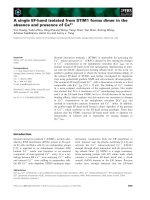
Figure 0 — Height and depth of a building
Licensed copy:RMJM, 29/08/2005, Uncontrolled Copy, © BSI
BS5588-5:1991
© BSI 05-1999
3
2.24
non-combustible material
any material capable of satisfying the performance
requirements specified in BS476-4, or any material
which when tested in accordance with BS476-11
does not flame or cause any rise in temperature on
either the centre (specimen) or furnace
thermocouples
2.25
pressure differential system (pressurization)
system of fans, ducts and vents provided for the
purpose of creating a pressure differential between
the fire zone and the protected space
2.26
protected
enclosed (other than any part which is an external
wall of a building) with fire-resisting construction
2.27
registered call
a call made on a car control station or from a landing
call button that is accepted by the control equipment
2.28
smoke shaft
an enclosed space in a building provided for venting
smoke from a firefighting stair or one or more
firefighting lobbies
2.29
vent
a window, rooflight, door, louvre, grille or other
device either open or capable of being opened to
permit the passage of air between a part of the
building and the external air
3 Use of this code
3.1 Background
When the fire service is called to a fire a speedy
response is expected of it. Considerable public
resources in modern communications and
mobilizing systems, fast efficient mobile appliances,
personnel and training are committed to this
objective, which is fundamental to effective
firefighting and rescue operations. However, the
time taken to reach the entrance of a building may
be but a fraction of the time it takes to travel
through the building to reach the fire and commence
firefighting operations.
Fire service personnel faced with a task of
firefighting on a floor high above the ground need to
be able to reach the fire quickly, with their
equipment, and having done so they need also to
have sufficient energy left for the arduous and
prolonged task of firefighting. Physical safety and
lives, their own and those of the occupants of the
building, and the preservation of the building and
its contents, may well be hazarded by delays in
reaching the fire floor. Having done all that it can to
limit response time, the fire service is therefore
dependent on the foresight of designers in providing
it with the necessary facilities to operate effectively
within the building when it arrives there. This
means that in high-rise buildings at least one of the
lifts needs to be readily available and of suitable
design for firefighters to use, i.e.a firefighting lift.
The firefighting lift may be separate from or part of
a group of lifts.
The benefits to the fire service from the provision of
firefighting shafts are not confined to high-rise
buildings. Fires in deep basements create
particularly difficult access problems in which
firefighting stairs and lifts can be invaluable. Also,
in buildings containing concentrations of
combustible materials in large areas above or below
ground level, firefighting stairs (but not necessarily
lifts) will afford ready and safe access.
In a fire the hazards for passengers who may
become trapped if a lift fails are so great that lifts
(other than lifts complying with BS5588-8 provided
for the evacuation of disabled persons) should not be
used as means of escape and the stairs should be
used instead: there have been many reported cases
of lift failures and casualties arising from the
ill-considered use of lifts during fires in buildings.
The principle of protecting lift wells, although not
necessarily for personal safety, is long-established
practice, but the lift machinery is equally important
and lift machine rooms have often not received the
attention which is necessary to ensure maximum
protection and reliability of the installation.
Unlike a normal passenger lift, a firefighting lift
needs to be able to transport fire service personnel
and their equipment with a high degree of safety
when there is a fire in the building. It is essential
that means to free passengers who may become
trapped in a stalled car are provided, even though a
duplicated power supply is provided.
Licensed copy:RMJM, 29/08/2005, Uncontrolled Copy, © BSI
BS5588-5:1991
4
© BSI 05-1999
It is normal fire service practice to take a
firefighting lift to a floor below that of the fire (floor
above if a basement fire) to avoid both fire service
personnel and the lift car being directly exposed to
the risk of injury or damage before the fire situation
can be assessed and firefighting started. Although a
firefighting lift will enable firefighters to approach a
fire without delay it cannot fully satisfy the needs
for fire service access within the building. A
firefighting lobby approach stair is also necessary
for four important purposes:
a) as means of final approach to the fire floor;
b) for floor-to-floor movement during firefighting
operations;
c) to serve as an essential assured and safe route
of egress for the fire service if the lift should fail
or its reliability become uncertain; and
d) for the firefighting lobby on the floor below the
fire floor to serve as a safe area where firefighters
and firefighting equipment may be assembled
before commitment to firefighting operations.
The advantage of fire service personnel using a lift
to reach the upper floors of a building will be lost if
it is then necessary to lay hose from the street to
deal with the fire. This means that wherever a lift is
to be used for firefighting access, a fire main and
landing valves will also be needed.
When planning firefighting stairs and the
structural accommodation for lift installations it is
not enough to anticipate fires only within the
occupied floor areas and to consider the firefighting
shaft as being free from risk. Experience has shown
that fires in such areas result in damage and
disruption out of all proportion to their size. These
fires also require the speedy intervention of the fire
service, and the structural design needs to take
account of the need to minimize the effect of such
fires on the lifts and stairs that firefighters will rely
on to reach them.
Reliability of power supplies and circuitry is yet
another important consideration. These are also
vulnerable to fire and need to be protected. The
effects of water ought also to be considered as there
have been incidents where lift control malfunction
and failure have occurred because water has
entered a lift well and reached electrical door
interlocks, car controls, etc. Such water can come
from many sources including open landing valves,
firefighting jets, burst hose or sprinkler discharges.
3.2 Relationship with means of escape
A firefighting stairway will normally be used for
means of escape and therefore will need to meet the
recommendations for protected stairways given in
the appropriate Part of BS5588.
No recommendations are made in this code for the
use of any lift for the purpose of escape in the event
of fire. However, BS5588-8 includes the
recommendation that, subject to the provision of
satisfactory fire procedures and management
control, a firefighting lift may be used for the
evacuation of disabled people in case of fire.
3.3 Relationship with statutory provisions
It is important to appreciate the relationships
between this code and the various statutory
provisions relevant to the design and construction of
new buildings and to the fire precautions to be
provided in existing buildings. The relevant
legislation indicated in general terms in3.4 has to
be complied with in the event of a conflict with this
code.
3.4 Building regulations
The design and construction of new buildings, and of
alterations of existing buildings, are controlled by
the following statutory provisions which are
collectively referred to as building regulations in
this code.
England and Wales: The Building Regulations;
Scotland: The Building Standards (Scotland)
Regulations;
Northern Ireland: The Building Regulations
(Northern Ireland).
It should be noted that some county and other
authorities in England and Wales have local powers
in respect of fire precautions, which may include the
provision of firefighting stairs and/or lifts.
3.5 Application of all the recommendations
Individual recommendations of this code should not
be applied in isolation because of their
interdependence and joint contribution to the
provision of a relatively safe environment for
firefighting.
NOTEWhere it would be impracticable to meet all the
recommendations when installing a firefighting shaft in an
existing building, it is suggested that the advice of the relevant
authorities be sought.
3.6 Provision and number of firefighting
shafts
The criteria for the provision and number of
firefighting shafts in many building types are given
either in building regulations or in the relevant Part
of BS5588. However, where no such guidance is
available the provision and number of firefighting
shafts should be based on the following.
a) Buildings or parts of buildings where:
1) the height (see2.18) of the surface of the
floor of the topmost storey (excluding any
storey consisting exclusively of plant rooms)
exceeds 15m; or
Licensed copy:RMJM, 29/08/2005, Uncontrolled Copy, © BSI
BS5588-5:1991
© BSI 05-1999
5
2) the depth (see2.5) of the surface of the floor
of the lowermost storey exceeds 10m;
should be provided with firefighting shafts each
containing:
i) a firefighting stair;
ii) firefighting lobbies provided with a fire
main;
iii) a firefighting lift installation.
NOTE 1The reference to parts of buildings covers situations
such as a tower block rising above a podium.
b) Buildings where:
1) the height (see2.18) of the surface of the
floor of the topmost storey exceeds 7.5m, with
the floor area of any storey above the ground
storey not less than 600m
2
; or
2) there are two or more basement levels each
with a floor area exceeding 900m
2
;
should be provided with firefighting shafts
each containing:
i) a firefighting stair;
ii) firefighting lobbies.
c) Sufficient firefighting shafts should be
provided such that on every storey:
1) with a height (see2.18) exceeding 18m; or
2) with a depth (see2.5) exceeding 10m; or
3) above the ground storey in buildings as
described in item b)1); or
4) below the ground storey in buildings as
described in item b)2);
the floor area on that storey served by any
firefighting shaft does not exceed 900m
2
and the
distance along which hose can be laid from the
doorway between the firefighting shaft and the
accommodation to any point on that storey does
not exceed 60m.
NOTE 2If the internal layout is not known at the design stage,
a direct line measurement of 40 m may be used for design
purposes, provided that the layout of the building when occupied
satisfies the 60m criterion.
3.7 Diagrams
The figures in this code are intended to clarify
concepts, and should not be taken as indicating the
only acceptable forms of planning.
NOTEDetails not relevant to the concept illustrated, for
example fire mains and landing valves, are not included.
3.8 Relationship with sprinkler installations
Sprinkler systems, provide an effective means of
controlling the outbreak of fire. However, the design
criteria in BS5306-2 are intended to control rather
than suppress fire. Fire brigade access to the parts
of a building affected by fire will still be required
even if a sprinkler system is installed. The
recommendations of this code of practice should
apply irrespective of the level of sprinkler
protection.
Licensed copy:RMJM, 29/08/2005, Uncontrolled Copy, © BSI
BS5588-5:1991
6
© BSI 05-1999
Section 2. Planning and construction
4 Firefighting shafts
4.1 General
A firefighting shaft provides a protected access
route for firefighters up or down a building. In most
cases it also serves as a means of escape for the
occupants and for normal circulation. The
recommendations in this section are for measures in
addition to those which may be necessary to fulfil
the means of escape function.
A firefighting shaft always contains a firefighting
stair and, on every storey served by the stair, a
firefighting lobby between the stair and the
accommodation. A firefighting lift opening into the
firefighting lobby may need to be provided in certain
buildings.
The function of the firefighting lift is to transport
firefighting personnel and equipment to save time
and effort. The firefighting stair is for
communication over short distances and as a line of
retreat should the firefighting lift fail, and the
firefighting lobby gives protection to the firefighting
lift and stair as well as being a bridgehead from
which the fire may be attacked.
4.2 Extent of firefighting stairs and lifts
NOTEThe terms “tall building”, “deep basement” and “large
floor area” are not defined, as the criteria for the provision and
number of firefighting shafts in many building types are given
either in building regulations or in the relevant Part of BS5588.
Where no such guidance is available the provision and number of
firefighting shafts is to be based on the criteria given in3.6.
4.2.1 Commentary
Firefighting shafts need to be provided in tall
buildings, buildings with deep basements, and
buildings with large floor areas. The firefighting
shaft ought to be located so that it allows access to
every part of every storey that it serves. Where storeys
are large more than one firefighting shaft may be
necessary to provide access within a reasonable
distance of a firefighting shaft.
Whilst it is preferable for the firefighting shaft to
serve all storeys of a building, this is not always
necessary. The following considerations affect the
extent of firefighting shafts and of the firefighting
lifts and stairs in them. The minimum extent of
firefighting lifts and stairs is shown inFigure 1.
In tall buildings and buildings with deep basements
the firefighting shaft ought to contain a firefighting
lift. Fire service personnel may need to check several
storeys when they arrive to assess the situation, and
the firefighting lift ought to serve all the storeys they
might need to reach.
Because the firefighting stair is the line of retreat if
the firefighting lift fails, the firefighting stair needs
to serve every storey served by the firefighting lift.
The lift and stair are also used together during
firefighting operations.
In large complexes, with a variety of uses, different
firefighting shafts may serve different parts of the
complex: for example, in a complex consisting of
high-rise offices over a shopping centre, the offices
could have a firefighting shaft that did not serve the
shopping centre. It is important that any such
arrangement is logical and simple, so that fire
service personnel have no difficulty in finding the
firefighting shafts serving the areas they need to
reach.
It is considered undesirable to recommend the
installation of a firefighting lift (within a means of
escape staircase) as it has the potential for
increasing the fire load. However, in the case of
refurbished buildings where design constraints
make the provision of a firefighting lift in the
firefighting lobby impracticable then subject to
additional measures [see4.2.2 g)] the lift may be
sited within its own fire-resisting shaft in the
firefighting stair enclosure. It has also been
considered undesirable to recommend this provision
in residential buildings as the lack of ongoing
statutory control makes the recommended measures
unenforceable.
Buildings or complexes which are not high and do
not have deep basements, but have a large floor area,
will still benefit from the provision of firefighting
shafts. A firefighting lift is not necessary in such
buildings because the vertical transport of personnel
and equipment is not a problem, but the firefighting
shaft ought to contain a firefighting stair and
firefighting lobbies.
To prevent smoke from a basement fire
smoke-logging the firefighting stair at all levels,
firefighting stairs serving storeys both above and
below ground level ought to be separated at ground
level.
Licensed copy:RMJM, 29/08/2005, Uncontrolled Copy, © BSI
BS5588-5:1991
© BSI 05-1999
7
4.2.2 Recommendations
The following recommendations are applicable.
a) Firefighting shafts should be provided in tall
buildings, buildings with deep basements, and
buildings with large floor areas.
b) Firefighting shafts should be provided with
firefighting lifts in the following cases:
1) in buildings with deep basements, in which
case the firefighting shaft should serve fire
service access level and all storeys below it;
2) in tall buildings, in which case the
firefighting shaft should serve fire service
access level and all storeys above it, although
the firefighting lift need not serve any storey
on which there is no entrance to any
accommodation [see item d)] or the topmost
storey of the building if it consists exclusively
of plant rooms;
3) in a building which is both deep and tall, in
which case the firefighting shaft should serve
all storeys, although the firefighting lift need
not serve any storey on which there is no
entrance to any accommodation [see item d)] or
the topmost storey of the building if it consists
exclusively of plant rooms. Storeys below fire
service access level may be served by a
different firefighting lift from that serving the
upper storeys, and any firefighting stair that
serves levels both above and below ground
level should be separated at ground level.
NOTEA fire-resisting partition containing a FD30S fire
door (see9.4.1) may be used to divide the stair.
c) Firefighting shafts in large floor area buildings
that are neither tall buildings nor buildings with
deep basements need contain only firefighting
stairs and firefighting lobbies.
Figure 1 — Minimum extent of firefighting stairs and lifts in tall buildings and
buildings with deep basements
Licensed copy:RMJM, 29/08/2005, Uncontrolled Copy, © BSI
BS5588-5:1991
8
© BSI 05-1999
d) If a building contains separate units of
accommodation with their own entrances from
common circulation spaces, for example as is the
case with some flats and maisonettes, there
should be access to each unit from a firefighting
lift, either directly or via a common circulation
space.
e) If a firefighting shaft contains a firefighting
lift, the firefighting stair in that shaft should
serve every storey served by the firefighting lift.
f) The stair from a firefighting shaft may be
extended into a part of the building not requiring
a firefighting shaft provided that either:
1) the firefighting shaft is extended
accordingly, including the provision of
firefighting lobbies and any fire main; or
2) the extension to the stair is separated from
the firefighting shaft by fire-resisting
construction [see9.3.2 b)].
g) It is considered acceptable to install the
firefighting lift in the firefighting stair enclosure
(seeFigure 1a) in the following circumstances:
1) the building is put to non residential use;
and
2) the firefighting lift is sited so that the
movement of fire brigade personnel between
the lift and the lobby does not impede the use
of the stair by the building occupants during
an evacuation; and
3) the building evacuation scheme is single
stage; and
4) if the lift is to be used for the evacuation of
disabled people the provisions of BS 5588-8 are
complied with; and
5) the firefighting lift is not to be used as a
goods or service lift; and
6) the lift well should be inspected monthly and
any combustible materials removed.
4.3 Siting of firefighting shafts
4.3.1 Commentary
Firefighting shafts ought to be sited against an
exterior wall to facilitate smoke control. In buildings
with a high fire risk or high fire load, firefighting
shafts need to be sited against an exterior wall, even
if a pressurization system is provided, to facilitate
firefighting and for the safety of fire service
personnel.
The separation of the accommodation from the
firefighting shaft (see4.4), together with the
provision of means for smoke control, is intended to
provide a substantially smoke-free environment for
firefighting operations.
If it is not possible to locate the firefighting shaft
against an exterior wall then the route from the fire
service entrance to the firefighting shaft needs to be
as short as possible and protected by fire-resisting
construction to ensure that fire does not affect the
route or cut off the means of escape for fire service
personnel fighting a fire within the building. The
layout of the firefighting shaft at fire service access
level ought to be such that firefighters entering the
firefighting lift and persons escaping down that
firefighting stair do not obstruct each other. Longer
corridors may be acceptable to a fire authority if
enhanced fire protection or facilities are provided,
e.g.the protected corridor serving only the
firefighting shaft; the provision of a second protected
corridor; the provision of a wet fire main.
The firefighting lobby at fire service access level
needs to be large enough to act as a command post
where firefighters and firefighting equipment may be
safely assembled. A building might have a building
control centre that could be used by the fire service,
or the fire service might use a mobile command
centre, etc., and such operational details ought to be
discussed by the developer with the fire service.
Vehicular access, including access to any inlet to a
dry fire main, may be required under building
regulations or local legislation, or may be covered in
the relevant part of BS5588.
4.3.2 Recommendations
The following recommendations are applicable.
a) At fire service access level, entry to a
firefighting shaft should be available either:
1) directly from the open air
[see Figure 2(a)(1) andFigure 2(b)]; or
2) by way of a protected corridor not
exceeding18m in length. The corridor should
be considered to be part of the firefighting
shaft, and any access to it from the
accommodation should be by way of protected
lobbies. It should not be necessary for persons
escaping down the stair to pass through the
firefighting lobby at fire service access level.
Where the corridor forms part of the means of
escape from the accommodation it should
be500 mm wider than that required for means
of escape purposes (to allow room for fire
service personnel to move towards the
firefighting shaft), and the firefighting lobby
should have a minimum area of 5m
2
clear of
any escape routes so that it can act as a fire
service mustering point [seeFigure 2(a)(2)].
b) Where a dry fire main is provided, there should
be appliance access to within 18m of the inlet
connection to the main, within sight of the
connection and with direct access thereto.
Licensed copy:RMJM, 29/08/2005, Uncontrolled Copy, © BSI
BS5588-5:1991
© BSI 05-1999
9
4.4 Layout of firefighting shafts
4.4.1 Commentary
It is essential that firefighting personnel, having left
the firefighting lift to enter the firefighting lobby, can
enter the firefighting stair enclosure in case of need
without having to traverse an area of risk within any
storey of the building. Therefore it is necessary that
the firefighting lift, lobbies and stair are within a
protected enclosure and that the firefighting stair is
as close as possible to the firefighting lift so as to
provide a means of escape for fire service personnel.
Fire protection for the firefighting stair and lift relies
on each being within a protected enclosure.
NOTE 1The firefighting lift landing doors are fire doors.
Access to the accommodation needs to be through a
lobby as a single fire door cannot provide adequate
protection to the firefighting stair and lift from a fire
in the accommodation. The lobby also serves as a
bridgehead from which firefighting operations can
be mounted.
NOTE 1aThe only exception is in the case of residential
accommodation, where due to the high level of compartmentation
between the residential units, the common ventilated access
corridor can act as a lobby.
Although in some countries it is required that a
firefighting lift be in a separate well, it has been
thought unreasonable to follow this course provided
that any additional risks can be minimized.
Accordingly, this code recommends that, like the
firefighting lift, other lifts within the same well
should not introduce significant additional fire risks
into the firefighting shaft. Entry from within the
building to any other lift in the same well has to be
through the same protected lobby from which the
firefighting lift is entered [see Figure 3(a)].
Figure 1a — Firefighting lift within escape stair [see 4.2.2 g)]
Licensed copy:RMJM, 29/08/2005, Uncontrolled Copy, © BSI
BS5588-5:1991
10
© BSI 05-1999
Figure 2 — Typical firefighting shaft layouts at fire service access level
Licensed copy:RMJM, 29/08/2005, Uncontrolled Copy, © BSI
BS5588-5:1991
© BSI 05-1999
11
Figure 3 — Banks of lifts that incorporate a firefighting lift
Licensed copy:RMJM, 29/08/2005, Uncontrolled Copy, © BSI
BS5588-5:1991
12
© BSI 05-1999
All access between the firefighting stair and
firefighting lift and the accommodation needs to be
solely via the firefighting lobby. Where it is
impractical to locate all adjacent lifts within the
firefighting shaft a dual-entry firefighting lift may
be provided with a separate firefighting lobby
accessible through a second set of lift doors
[seeFigure 3(b)]. However, because of the additional
risks that this arrangement places on the integrity of
the firefighting shaft, certain additional facilities
need to be provided by the lift control system, the
number of such lifts is limited, the fire-resistance of
the main lift lobby lift landing door needs to be
increased to 60min [to meet9.3.2 b)], and any storey
served by a single firefighting lift ought not be served
by a dual-entry firefighting lift.
NOTE 2The operation of passenger lifts within firefighting
shafts is covered in clause14.
Whenever possible a firefighting shaft ought not to be
exposed to the dangers of radiant heat from an
adjacent face of the building. Where this is not
possible the construction of the firefighting shaft
needs to take into account the heat radiation it could
be exposed to during a fire.
4.4.2 Recommendations
The following recommendations are applicable.
a) Access to the accommodation from the
firefighting lift or stair (by way of a firefighting
lobby) should be provided at all levels served by
the firefighting shaft.
NOTEIf the firefighting lift does not serve the topmost
storey of a building (see4.2.2), the firefighting lobby on the
topmost storey serves the firefighting stair only. If the
topmost storey consists only of the firefighting lift motor
room, no lobby is necessary.
b) Any storey served by a single firefighting lift
should not be served by a dual-entry firefighting
lift and not more than half the firefighting lifts
serving any storey may be dual-entry lifts.
c) Goods lifts and service lifts should not be
located within firefighting shafts.
d) Passenger lifts should not be located within a
firefighting shaft unless the lift cars are
constructed in accordance with11.2 b), are
clearly and conspicuously marked “Do not use for
goods or refuse”, and have access only from a
firefighting lobby.
e) Where a firefighting lift is dual-entry the lift
landing doors to the main lift lobbies should be
separated from the accommodation by an
enclosure with a fire resistance of not less
than30min [seeFigure 3(b)]. The doors to this
enclosure should be self-closing, but means of
overriding the self-closing device may be provided
by a hold open system incorporating an automatic
release mechanism complying with BS5839-3.
The automatic release mechanism should release
the door to close automatically in the event of
each or any of the following:
1) the detection of smoke by suitable automatic
apparatus mounted at high level in the
accommodation adjacent to a door to the main
lift lobby enclosure;
2) failure of the power supply;
3) operation of the firefighting lift switch;
4) operation of the fire alarm system;
5) a manual operation at a central control
point;
6) actuation of any automatic fire
extinguishing system (e.g.a sprinkler system);
7) the removal, for whatever reason, of a smoke
detector in a fire detection zone protecting
accommodation directly accessible from the
firefighting shaft.
Such doors should be suitably marked on both
sides, at about eye level, with the appropriate
sign complying with BS5499-1.
f) Where the firefighting shaft is sited against an
exterior wall, if any glazed area [unless it
complies with9.2 and9.3.2 a)1)] or opening in
the exterior wall of the firefighting shaft is less
than 500 mm from the junction of the firefighting
shaft with the exterior wall, then the fire
resistance of the external wall immediately
adjacent to the glazed area or opening should be
not less than 1h from both sides for a horizontal
distance of 500mm [seeFigure 4(a)].
g) If one or more walls enclosing the firefighting
shaft are exterior walls, then:
1) the side nearest the accommodation of any
exterior wall facing or adjacent to the
firefighting shaft should have a fire resistance
of 2h; or
2) the side internal to the firefighting shaft of
any exterior wall facing or adjacent to the
accommodation should have a fire resistance
of2h;
unless the distance between the firefighting
shaft and the accommodation is not less
than5m [see Figure 4(b), Figure 4(c)
andFigure 4 (d)].
Licensed copy:RMJM, 29/08/2005, Uncontrolled Copy, © BSI
BS 5588
-
5
:
1991
© BSI 05-1999
13
Figure 4 — Examples of protection of the firefighting shaft from external fire
Licensed copy:RMJM, 29/08/2005, Uncontrolled Copy, © BSI
BS5588-5:1991
14
© BSI 05-1999
h) If the firefighting shaft contains sanitary
accommodation, such accommodation:
1) should not be used as a cloakroom;
2) should not contain any portable heating
appliances;
3) should not contain any gas appliance other
than a water heater or incinerator.
i) The firefighting shaft should not contain any
cupboards or provide access to service shafts
serving the remainder of the building.
j) Only services associated with the firefighting
shaft should pass through or be contained within
the firefighting shaft.
k) The doors between the firefighting stair and
firefighting lobby should be kept free from any
fastenings.
5 Firefighting stairs
5.1 Commentary
Firefighting stairs need to be sufficiently wide to be
easily used by firefighting personnel carrying
firefighting equipment. Firefighting stair enclosures
ought to be provided with means for smoke control to
ensure that they remain relatively smoke-free; they
also need to be subdivided at ground level to prevent
smoke from basement storeys from penetrating the
stair enclosure above ground level.
5.2 Recommendations
The following recommendations are applicable.
a) Firefighting stairs should be designed in
accordance with the recommendations of
BS5395-1, with a minimum width between the
walls or balustrades of 1.1m.
This width should be maintained clear for a
vertical distance of 2.0m, measured from the
pitch line or landing floor level, with the
following exceptions:
1) stringers, each intruding into the stair not
more than 30mm;
2) handrails, each intruding into the stair not
more than 100mm.
b) Firefighting stair enclosures should be
provided with facilities for smoke control
(seeclause8).
c) Firefighting stairs serving floors both above
and below ground level should be separated at
ground level by a fire door [seeFigure 2(b)(1)].
d) Lighting in firefighting stair enclosures should
comply with clause16.
6 Firefighting lobbies
6.1 Commentary
Lobbies have to be of sufficient size to enable fire
service personnel to lay out hose and connect it to a
landing valve (if provided) without undue
congestion, but the lobby should not be so large as to
encourage any form of storage or unauthorized use.
The layout of a firefighting lobby and the positions of
all doors should reduce, as far as is practicable, risks
arising from:
a) the creation of dead-ends (in which firefighters
may become cut off from access to the safety of the
stair or become disorientated in poor visibility);
and
b) the direct exposure of lift landing doors to the
effects of fire through the doorway leading into
the accommodation.
Subject to certain restrictions, sanitary
accommodation may be accessed by way of the
firefighting lobbies.
In the case of residential buildings designed in
accordance with BS 5588-1 it is accepted that the
protected ventilated common corridors/lobbies will
provide sufficient protection of the firefighting stair
without the need to provide additional dedicated
ventilated lobbies.
6.2 Recommendations
The following recommendations are applicable to all
buildings except residential buildings designed in
accordance with BS5588-1.
a) Firefighting lobbies should not form part of a
general circulation route within any storey except
for circulation between storeys and to sanitary
accommodation. If the wall between the
firefighting lobby and the sanitary
accommodation is not the wall enclosing the
firefighting shaft [i.e.does not comply
with9.3.2 b)] then the wall between the
firefighting lobby and the sanitary
accommodation should comply with9.3.2 c) and
the sanitary accommodation should not contain
any fire risks [see4.4.2 h)].
b) Firefighting lobbies should have a clear floor
area of not less than 5m
2
. The clear floor area
should not exceed 20m
2
for lobbies serving up to
four lifts, or 5m
2
per lift for lobbies serving more
than four lifts. All principal dimensions should be
not less than 1.5m and should not exceed 8m in
lobbies serving up to four lifts, or 2m per lift in
lobbies serving more than four lifts.
c) Firefighting lobbies should be provided with
facilities for smoke control (see clause8).
Licensed copy:RMJM, 29/08/2005, Uncontrolled Copy, © BSI
BS5588-5:1991
© BSI 05-1999
15
NOTEHowever, in the case of residential buildings, there is
no need to increase the area of ventilation beyond that
recommended in BS5588-1.
d) Where the firefighting shaft contains a
firefighting lift, the firefighting shaft should
contain a fire main.
e) Firefighting lobbies should be clearly and
conspicuously marked with a notice complying
with BS5499-1, stating “Firefighting lobby: do
not use for storage”.
f) Lighting in firefighting lobbies should comply
with clause16.
7 Fire mains and landing valves
NOTEAlthough this code does not include a recommendation
for the provision of fire mains in buildings provided with
firefighting stairs but not a firefighting lift, this should not
preclude the provision of fire mains in such buildings.
7.1 Commentary
Landing valves ought to be sited where personnel
can safely lay out and charge hose lines before
entering the fire compartment, and ease of access,
exposure to fire from the accommodation if a door is
open, obstruction of fire doors by the hose line and
the risk of unintentional discharge of water hitting
the lift doors or controls need to be considered when
siting landing valves.
7.2 Recommendations
The following recommendations are applicable.
a) Wet and dry rising (and falling) fire mains
should be installed in accordance with BS5306-1
and a landing valve should be installed in each
firefighting lobby and at fire service access level.
b) Landing valves should be sited and their
outlets directed:
1) so that access to them is unobstructed;
2) away from lift landing doors so there is
minimal risk of any discharge of water from
the outlet coming into contact with lift controls
and communications equipment or of flowing
into the lift well (see clause12);
3) so that hoses can be connected, charged and
advanced into the accommodation without
excessive kinking or obstruction to doors and
exit routes.
c) Where dry falling mains serve basements 10m
or more below ground, either:
1) the falling main should serve only storeys
below the charging point; or
2) a pressure limiting device should be fitted to
prevent excessive pressure developing at
landing valves below the charging point.
8 Smoke control
8.1 Commentary
Effective means are needed to minimize the
possibility of serious contamination of the
firefighting shaft by smoke, such as the provision of
openings for natural ventilation, determined in
certain circumstances by the configuration of the
building, or by a pressurization system. Because of
the difficulty of ventilating smoke from basement
levels, natural ventilation is acceptable only for
basements of limited depth; firefighting shafts
serving deeper basements need to be pressurized. No
provision need be made for smoke venting in the lift
well over and above the permanent ventilation
required by BS5655-1 andBS5655-2.
Whatever solution is proposed the effects of problems
created by the prevailing wind direction and high
winds need to be considered as they can markedly
influence the effectiveness of both natural ventilation
and pressurization systems. The circumstances in
which it may be necessary for the fire service to
exercise control over the means of ventilation to meet
operational needs at the time of a fire also need to be
considered.
BS5588-4 gives guidance on the use of
pressurization for the purposes of smoke control in
protected escape routes but, although the principles
behind the recommendations of BS5588-4 remain
valid, some of its recommendations are not
appropriate for the pressurization of firefighting
shafts. In particular, the design conditions reflect
fire service operational practice, i.e.connecting hose
to the fire main outlet on the storey adjacent to the
fire storey and approaching the fire storey via the
firefighting stair.
In order to keep the firefighting lobby relatively
smoke-free before firefighting operations commence
it is necessary to hold back the hot smoke and gases
produced by a fully developed fire, and hence the
open door airflow needs to be higher than that
necessary for means of escape. Although the velocity
of hot smoke and gases could reach5m·s
–1
,
firefighting operations, such as the use of a jet, ought
to contribute significantly to the holding back of hot
smoke and gases.
Designers of pressurization systems also need to take
into account possible interference with, or from,
pressurization systems for escape routes, the use of
mechanical ventilation or air conditioning plant
which is operating in an abnormal mode to clear the
smoke from accommodation areas, leakage through
the building fabric, the number of doors open or
partly open, gaps around doors (including lift doors)
and the effect of doors being opened and closed when
the pressurization system is operating.
Licensed copy:RMJM, 29/08/2005, Uncontrolled Copy, © BSI
BS5588-5:1991
16
© BSI 05-1999
8.2 Recommendations
The (following recommendations are applicable.
a) Firefighting shafts serving basements more
than 9m below ground level should be provided
with a pressurization system.
b) All other firefighting shafts should be provided
with either a pressurization system (see8.3) or
natural ventilation (see8.4);
8.3 Recommendations for the pressurization
of firefighting shafts
Pressure differential systems should be designed
and installed in accordance with BS5588-4.
8.4 Recommendations for the venting of
firefighting shafts by natural means
NOTE 1Firefighting shafts serving basements with floor levels
more than 9m below ground level should be pressurized
[see8.2 a)].
The following recommendations are applicable.
a) An openable vent with an area of not less
than5 % of the horizontal cross-sectional area of
the firefighting stair enclosure should be
provided at the top of the stair enclosure, sited
where it will not be unduly affected by wind
pressures
1)
. The vent should be provided with a
remote control mechanism located adjacent to the
fire service access doorway and clearly marked as
to its function and means of operation. The
mechanism should be capable of opening and
closing the vent. All connections between the
remote control and the opening mechanism
should be within the firefighting shaft. Where
any part of the remote control mechanism is
powered by electricity, a secondary supply should
be provided (seealsoclause16).
b) For firefighting stairs adjacent to external
walls, openable vents with an area of not less
than 15% of the horizontal cross-sectional area of
the stair enclosure should be provided at each
storey level above ground level. Any door opening
directly to open air should be considered to
contribute to the requirements for venting and
where possible such doors should not be kept
locked.
c) Firefighting stairs that:
1) serve only basement levels less than 9m
below ground level; and
2) lead directly to a final exit; need not be
provided with openable vents at any level.
NOTE 2The door to the final exit serves as a vent.
d) Lobbies above ground level should be provided
with openable vents with a free area of not less
than 25% of the horizontal cross-sectional area of
the firefighting lobby with the vent(s) sited as
near to the ceiling as is practicable.
e) Firefighting lobbies at each basement level in a
particular firefighting shaft should each be
provided with a vent at high level having a
minimum cross-sectional free area of 1m
2
. The
vent should discharge direct to open air or into a
smoke shaft, serving only that storey, with a
cross-sectional area not less than that of the vent.
Smoke shafts serving basements should
discharge direct to open air at ground level where
the exits from the building and fire brigade access
would not be affected by the smoke discharge.
Any cover to a smoke shaft serving a basement
should be either a metal grille designed to
prevent blockage of the shaft by rubbish, or both
breakable and easily accessible from the
appropriate fire service access level.
f) Unless vented direct to open air, the
firefighting stair should be vented into a separate
smoke shaft, and not into the smoke shaft serving
the firefighting lobbies. Any smoke shaft serving
a firefighting stair or lobbies should be fully open
to the external air at top and bottom and the
outlets should be sited where they will not be
adversely affected by wind pressures
1)
.
Openings into the smoke shaft should be
guarded to a height of not less than 1.1m.
g) Smoke shafts serving storeys above ground
level should have:
1) a minimum internal area of 25% of the
lobby floor area, or 3m
2
, whichever is the
greater, with a minimum internal dimension
of1m, where serving lobbies;
2) a minimum internal area of 15% of the
horizontal cross-sectional area of the stair
enclosure or 1.5m
2
, whichever is the greater,
with a minimum internal dimension of 0.75m,
where serving a stair.
h) All openable vents provided for smoke control
(with the exception of vents sited above a stair
[see item a)] should be outward opening, should
not be top hung, should open a minimum of 30°,
should be clearly identifiable and accessible and
should be fitted with:
1) simple lever handles; or
2) rotary drives to simple rack or gear operated
devices; or
1)
Further information is given in CP 3: Chapter V: Part 2 and in the Wind Loading Handbook, HMSO.
Licensed copy:RMJM, 29/08/2005, Uncontrolled Copy, © BSI
BS5588-5:1991
© BSI 05-1999
17
3) locks which can be operated with a
square-ended key 8mm× 8mm in
cross-section and 25mm deep and which
should be agreed with the local Fire Authority.
i) Permanent vents should not be provided.
9 Construction of the firefighting shaft
9.1 Commentary
The construction separating the firefighting shaft
from the rest of the building, and also the internal
walls of the firefighting shaft, need to be sufficiently
robust to withstand mechanical damage both in
day-to-day use and during the course of a fire. That
part of the structure which separates the firefighting
shaft from areas of risk needs to have a high level of
fire resistance and, whilst the fire resistance
requirement for the firefighting shaft may be greater
than that for the rest of the building, this ought not
to be interpreted to mean that the firefighting shaft
would survive collapse for any longer than the
primary structural elements in the rest of the
building. The extra fire resistance ought to be
regarded as a factor of safety.
The fire resistance of the shaft will be affected by any
weak points in the construction of walls, floors, etc.
Attention needs to be paid to detailing, particularly
the joints between dry linings and floor slabs, and to
the fire stopping of any holes in walls or floors made
for the passage of cables, pipes, etc.
Although the preferred location for the firefighting
shaft is against an exterior wall, there is a possibility
that fire in the accommodation adjacent to the
firefighting shaft could threaten the firefighting
shaft if it broke through an opening in the exterior
wall, or through the exterior wall itself, and flames
were fanned horizontally along the face of the
firefighting shaft. Although exterior walls need not
resist fire from within a building, it is necessary for
openings in exterior walls to firefighting shafts to be
protected by fire-resisting construction if they are
sited close to the perimeter of the firefighting shaft
(see alsoFigure 4).
9.2 Recommendations for structure and
materials
The following recommendations are applicable.
a) Walls (other than external walls) and floors
enclosing or separating firefighting lift wells,
machine rooms, stairs, lobbies or smoke shafts
should be constructed from materials of limited
combustibility.
b) Walls enclosing or separating firefighting lift
wells, machine rooms, stairs, lobbies or smoke
shafts should be constructed from materials with
a durability and resistance to impact damage not
less than that given in Appendix A, and whose
fire resistance, durability and resistance to
damage is not significantly reduced by the
absorption of water resulting from firefighting
operations and/or the operation of sprinklers.
NOTEMaterials such as brick and concrete are deemed to
satisfy the recommendations ofAppendix A.
c) Ceilings, stairs and landings within the
firefighting shaft should be constructed from
materials of limited combustibility.
d) Internal surfaces to walls and ceilings
enclosing or separating firefighting lift wells,
machine rooms, stairs, lobbies or smoke shafts
should be class0.
e) Ducts and ductwork should comply with
BS8313 and BS5588-9 as appropriate.
9.3 Fire resistance
9.3.1 Commentary
Satisfactory performance of fire resistance of
structural elements is ascertained by compliance
with one of the following:
a) specifications tested, or assessed, in accordance
with the appropriate Part of BS476;
NOTERequirements made in connection with statutory
provisions may still refer to BS476-8, although it has been
superseded by BS476-20, BS476-21, BS476-22 and
BS476-23, with the tests relevant to loadbearing elements
published in part 21, and those for non-loadbearing elements
in part 22.
Brief details of these tests are given in PD6520.
b) appropriate British Standard specifications or
codes of practice;
c) specifications referred to under building
legislation.
9.3.2 Recommendations
The following recommendations are applicable.
a) Fire resistance, where recommended in this
code, implies the following:
1) for walls and partitions, compliance for
loadbearing capacity (where appropriate),
integrity and insulation;
2) for glazed elements, compliance for the
appropriate criteria (see9.5);
Figure 5 — Figure deleted
Licensed copy:RMJM, 29/08/2005, Uncontrolled Copy, © BSI
BS5588-5:1991
18
© BSI 05-1999
3) for doors, compliance for integrity when
each side is exposed separately to test by fire,
except in the case of lift landing doors, where
performance is in respect of exposure of the
landing side only.
b) Construction separating a firefighting shaft
from other parts of a building or areas of risk
should have a fire resistance of not less than 2h
for the sides remote from the firefighting shaft
and not less than 1h for sides internal to the
firefighting shaft.
c) Other parts of the construction enclosing or
separating firefighting lift wells, machine rooms,
stairs, lobbies and smoke shafts should have a
fire resistance of not less than 1h from each side,
except that openings of minimum size necessary
for ropes and cables are permitted in the
construction separating a lift machine room from
a lift well.
9.4 Fire doors
NOTEThe term “fire door” includes both the door frame and
the door leaf or leaves.
9.4.1 Commentary
The performance of a fire door when tested in
accordance with BS476-22 is judged by its time to
failure (in minutes) for the criteria of “integrity” and
“insulation”; regulations and codes of practice do not
normally, however, specify any performance for
insulation. For the purposes of this code, fire doors
are designated by reference to their required
performance (in minutes) for integrity only, e.g.a
reference FD60 implies that the door in that
situation should achieve not less than 60min
integrity when tested in accordance with BS476-22,
and a reference FD30 implies not less than 30min
integrity. Where doors are also required to retard the
passage of smoke the suffix “S” is added.
9.4.2 Recommendations
The following recommendations are applicable.
a) Fire doors protecting openings in fire-resisting
structures should have a fire resistance of at least
one-half of that required for the structure, but in
no case less than 30min.
NOTE 1In the early stages of fire it is unlikely that the door
between the firefighting lobby and the accommodation would
be directly attacked by fire, although the wall separating the
firefighting shaft and the accommodation might well be. The
main function of the door at this point is to ensure that the
firefighting lobby remains relatively smoke free. During
firefighting operations the door between the firefighting shaft
and the accommodation at the fire floor would be open and
therefore its level of fire resistance is relatively unimportant,
as is the fire resistance of the doors between the firefighting
shaft and the accommodation at levels not affected by fire.
b) Fire doors (except lift landing doors and doors
to and within pressurized firefighting shafts)
should, when tested in accordance with
BS476-31.1 with the threshold taped and
subjected to a pressure of 25Pa, have a leakage
rate not exceeding 3m
3
/h per metre. When
installed, the threshold gap should be sealed by a
seal either with a leakage rate not
exceeding3m
3
/h per metre at 25Pa or just
contacting the floor; where this is impracticable
the threshold gap should not exceed 3mm at any
point.
c) Fire doors, except lift landing doors, or doors to
a service duct [see item f)], should be fitted with a
self-closing device (other than rising-butt hinges)
that:
1) should be of a type that cannot readily be
disconnected or immobilized and does not
embody a stand-open action;
2) should override any latches fitted to the
door, or in the absence of a suitable latch or
other positive device for holding the door shut
in its frame, should be of a type that has been
shown by test in accordance with BS476:
Part 8 or Part 22 to be capable of holding the
door closed in the frame for a sufficient period
of time for the closing role to be taken over by
a thermally activated sealing device (such as
an intumescent seal), or throughout the full
period of exposure if such seals are not
incorporated.
d) Unless shown to be satisfactory when tested in
accordance with BS476-8 or BS476-22, no part
of a hinge on which any fire door is hung, and
which provides the means of support at the
hanging edge, should be made either of
combustible material or of non-combustible
material having a melting point of less than
800°C.
e) Hold-open systems should not be fitted to fire
doors to firefighting lobbies and stairs.
f) A fire door to a service duct, in lieu of being
self-closing, should have means to enable it to be
kept locked shut when not in use and be so
marked on the outside with the appropriate sign
complying with BS5499-1.
g) Any fire door [except one referred to in item f)]
should be marked on both sides, at about eye
level, with the appropriate sign complying with
BS5499-1 to the effect that it should be kept
closed when not in use.
NOTE 2Advice on the provision of door furniture for fire doors
is given in Code of practice for hardware essential to the optimum
performance of fire-resisting timber doorsets(1983), prepared by
and available from the Association of Builders’ Hardware
Manufacturers, Heath Street, Tamworth, Staffordshire B777JH
and BS8214, Code of Practice for fire door assemblies with
non-metallic leaves.
Licensed copy:RMJM, 29/08/2005, Uncontrolled Copy, © BSI
BS5588-5:1991
© BSI 05-1999
19
9.5 Glazed areas
9.5.1 Commentary
Partitions, doors and windows can be glazed with a
variety of products, e.g.traditional annealed wired
glass based on soda-lime-silica or clear borosilicate
glass. Although able to satisfy the integrity
requirements of BS476-22 for periods in excess
of 90min, these permit local high heat transmission
and radiation through the glass and so are unable to
satisfy the requirement for insulation for more than
a few minutes. Such heat transmission and
radiation would constitute a hazard to firefighting
personnel. Some laminated glasses (intumescent or
gel-interlayer) can achieve in excess of 90min for
integrity and insulation in specific glazing
constructions.
NOTEPD6512-3 gives advice and information on the
performance of glazed elements in buildings.
The type of glass permitted in walls required to be
fire-resisting depends on whether:
a) the glazed element needs to afford the same
level of protection against fire as the remainder of
the enclosure in which it is situated; or
b) the glazed element only needs to afford
protection against the passage of flame and hot
gases.
9.5.2 Recommendation
Construction which is required to be fire-resisting,
enclosing or within the firefighting shaft, should not
contain glazed areas unless:
a) it is an external wall [other than a wall that
should be fire-resisting (see4.4.2)]; or
b) the glazed element complies with9.2
and9.3.2 a)1); or
c) the glazed element is fire-resisting in terms of
integrity, the glazed area is provided in a fire
door, and its area does not exceed 0.1m
2
.
9.6 Flooring and floor coverings within the
firefighting shaft
9.6.1 Commentary
Floor coverings need to be fully secured to the floor,
with floors being maintained so as to minimize the
risk of slipping on the floor or floor covering when it
becomes wet. As the slip resistance of resilient floor
surfaces is reduced by contamination by dust or
materials such as oils or grease, it is essential that
they are cleaned frequently. The flammability of any
textile floor covering needs to be low.
9.6.2 Recommendations
The following recommendations are applicable.
a) All floorings and floor coverings should be
chosen so as to minimize slipperiness when wet,
and resilient floor surfaces should be maintained
in accordance with BS6263-2, with only emulsion
polish (i.e.not wax polish) being used.
b) Textile floor coverings should:
1) when tested, together with any underlay, in
accordance with BS4790, using the test
procedure reflecting the method used for
securing the floor covering to the floor, either
i) not ignite; or
ii) have effects of ignition on both the
use- and under-surfaces not extending
beyond a circle of radius 35 mm centred on
the central point of application of the nut;
2) be firmly secured to the floor, with any
adhesive used non-water soluble;
3) be interrupted at all doors to and within the
firefighting shaft along the line of the
threshold of the doorway with a metal or other
non-combustible strip not less than 50mm
wide.
Licensed copy:RMJM, 29/08/2005, Uncontrolled Copy, © BSI