Critical considerations for successful hydraulic fracturing and shale gas recovery
Bạn đang xem bản rút gọn của tài liệu. Xem và tải ngay bản đầy đủ của tài liệu tại đây (1.6 MB, 8 trang )
Copyright 2010, AADE
This paper was prepared for presentation at the 2010 AADE Fluids Conference and Exhibition held at the Hilton Houston North, Houston, Texas, April 6-7, 2010. This conference was sponsored by the
Houston Chapter of the American Association of Drilling Engineers. The information presented in this paper does not reflect any position, claim or endorsement made or implied by the American
Association of Drilling Engineers, their officers or members. Questions concerning the content of this paper should be directed to the individuals listed as authors of this work.
Abstract
Deep matrix hydraulic fracturing is a precondition for
transforming low permeability shale gas reservoirs into
commercial assets; however, stimulating production involves
more than increasing fracture permeability hydraulically.
Planning and coordinating multiple services and designing
multi-functional frac fluids are critical elements for project
success.
Integrating the various frac services into a seamless
operation requires up-front planning that includes a project
survey and evaluation to determine the appropriate service and
chemical options required for a low-risk, safe and productive
operation.
An integral part of the planning process is the selection of
frac fluid components to control bacterial growth, corrosion
and scale production. An all-purpose lubricant and surface
tension reducer are key components for reducing hydraulic
friction and increasing flow-back volumes, respectively.
Finally it is important to ensure that all the frac fluid
components are compatible with each other, the frac water
itself and the formation material to avoid issues during the
fracturing process, flow-back period and production cycles of
the well. Furthermore, an integrated chemical program from
the fracturing through production will ensure a seamless
transition and comprehensive risk management program
throughout the life of the well.
This paper describes the process, from start to finish, how
project management, careful frac-fluid additive selection and
performance monitoring can optimize hydraulic fracturing
operations. In addition, laboratory data are presented to
illustrate the basis of fluid design and field data are presented
to highlight the success of this multi-disciplined approach to
improve unconventional shale gas recovery.
Introduction
Traditionally, conventional natural gas has been produced
from sandstone and carbonate rock formations. More recently,
however, the operators have begun to focus on unconventional
natural gas reserves extracted from low permeability, tight
sandstones, shale gas and coal bed methane formations to
increase the production of clean burning fuel. Hydraulic
fracturing is a proven technological advancement that allows
natural gas producers to safely recover natural gas from deep
shale formations.
The use of deep matrix hydraulic fracturing as the
preferred completion technique has been a key factor in
unlocking the potential of unconventional gas plays. Much
has been learned since the first commercial fracture treatment
was performed in the late 1940s
1
.
It didn’t take long to
discover that fractures created by hydraulic fracturing fluids
tended to close off unless a proppant was included in the frac
fluid design. It was also discovered that frac fluids required
elevated viscosity to create adequate fracture width and
proppant transport and to minimize leak-off
1
.
The acceleration in gas production technology and
improved hydraulic fracturing techniques can be attributed to
the Barnett shale activity in an area around Fort Worth, Texas.
The first Barnett horizontal well was drilled in 1992, but in the
ensuing two decades sophisticated processes using horizontal
drilling and sequenced, multi-stage hydraulic fracturing
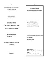
technologies were developed. As the Barnett Shale play has
matured, natural gas producers laid the foundation for the
water frac technology to spread to the other shale gas
formations across the U.S. (Figure 1) and Canada
2
.
The driving factors for this phenomenon were primarily
tied to cost cutting, depletion of permeability or fractures that
were not performing as well as expected. Aside from an
increase in natural gas pricing, advances in horizontal drilling
and hydraulic fracturing technology are responsible for
today’s unconventional natural gas recovery
3
.
Hydraulic Fracturing Fluids
Hydraulic fracturing involves pumping specialized fluids
into a formation at a specified rate and pressure to generate
fractures in the formation. For shale gas, fracture fluids are
mixed with additives that help the water to carry sand
proppant into the fractures. Once the fracture has initiated,
additional fluids are pumped into the wellbore to increase the
fracture length and to carry the proppant deeper into the
formation. Additional fluid volumes are needed to
accommodate the increasing length of opened fractures in the
formation.
The frac fluids used for gas shale stimulations include a
variety of chemical additives depending on the specific well
being fractured. These chemical treatments are injected at very
low concentrations with up to 12 chemical additives
depending on the properties of the water and the shale
formation. Each component serves a specific, engineered
AADE-10-DF-HO-08
Critical Considerations for Successful Hydraulic Fracturing and Shale Gas
Recovery
Jennifer Fichter, Alexander Bui, Greg Grawunder, and Tom Jones; Baker Hughes
2 J. Fichter, G. Grawunder, A. Bui, and T. Jones AADE-10-DF-HO-08
purpose
4
. The predominant chemicals currently used for
fracture treatments in the gas shale plays are friction-reducing
additives (called slick water)
5
.
The addition of friction reducers allows fracturing fluids
and proppant to be pumped to the target zone at a higher rate
and reduced pressure than if water alone were used. In
addition to friction reducers, other possible additives include
biocides to prevent microorganism growth; scale inhibitors to
prevent deposition of scale due to mixing of the fracture and
connate water; oxygen scavengers and other stabilizers to
prevent corrosion of metal pipe; and acids that are used to
remove drilling mud damage within the near-wellbore area
6
.
Project Management
As an operator begins a new shale play fracturing program,
it is critical to have a comprehensive viewpoint, not limiting
the focus to the pumping of the frac job, but also considering
how the drilling and stimulation processes will impact the day-
to-day operations of the field. As part of this process, it is
important to take a systematic approach when evaluating what
chemicals/additives should be introduced to the fluids during
the fracturing process. This approach involves several key
process steps: 1) a detailed survey to understand the system;
2) thorough chemical selection process including both field
and laboratory evaluations; 3) careful consideration on how to
implement the chemical programs; and 4) a comprehensive
monitoring and optimization program. The components of
this process will be demonstrated in the remaining sections of
this paper as we address bacterial and scale control, reduction
of friction during the fracturing process and addition of Flow-
Stimulator Additives to reduce the formation surface tension,
allowing for faster return of the frac water.
Frac Fluid Additive Selection
Bacterial Control
Due to the large volumes of water used during the
hydraulic fracturing process, the fracturing water sources are
most commonly stored in lined or unlined earthen pits that are
open to the atmosphere. Because the pits are open to the
atmosphere, dust, rain, and surface run-off can be introduced
into the pit water. The untreated fracturing waters can sit
dormant in the pit for days to months prior to the start of the
fracturing job. In many cases, the flowback water from the
fracturing operation is reused, resulting in the mixing of
several different water sources. In addition, common frac
fluid additives such as polyacrylamide friction reducers,
sugar-based polymers/gels and other organic compounds can
serve as food sources for bacteria in the frac water. All of
these practices lead to the potential for bacterial contamination
in the reservoir and downhole
If the frac fluid was not properly treated with a
microbiocide to control bacterial activity, fracturing water
bacteria can become established downhole and near wellbore
during the fracturing process and the subsequent shut-in
period
7
. Once bacteria become established downhole, the
contamination can be introduced into the separator, water
tanks, flow lines and disposal facilities downstream. Bacterial
contamination can result in biogenic sulfide production
(souring), iron sulfide (black water) formation, plugging
issues, and corrosion failures of downhole equipment, surface
separation and storage tanks and flowlines. Prevention of
bacterial contamination requires a quality bacterial control
program.
Lubricity (Friction Reduction)
With the growing popularity of slickwater fracturing, much
greater emphasis has been placed on the performance and
versatility of friction reducers. Most friction reducers used are
polyacrylamide-based, and can carry either an anionic,
nonionic or cationic charge
8
. In most applications, anionic
friction reducers are preferred due to their performance and
cost relative to cationic friction reducers. As the salinity of
the frac water increases, cationic friction reducers can become
more economical, but usually only in water containing greater
than 5% total dissolved solids.
The factors affecting friction reducer performance include
pH, temperature, salinity and compatibility with other frac
additives. The characteristics of friction reducers that
determine performance include molecular weight, charge,
unwinding/hydration speed and shelf life. Due to past
problems of incompatibility-related pressure problems, all frac
fluid additives must be pre-screened for compatibility and
performance in source waters prior to the fracturing process.
Additionally, the speed of hydration of a friction reducer
polymer is critical and should be evaluated. Due to growing
restrictions by regulatory agencies, greater volumes of early
flow-back waters will be reused. The increasing suspended
solids and salinity of frac waters will require salinity-tolerant
friction reducers, such as high-brine anionic friction reducers
and cationic friction reducers.
Interactions between a friction reducer and biocide can
result in consumption of both products, resulting in greater
quantities being needed for effective friction reduction and
biocidal activity
9
. This problem is especially prevalent when
the frac fluid additives are provided by more than one
chemical supplier. Through laboratory and field evaluations,
these interactions can be evaluated and compatibility indices
can be established.
Scale Inhibition
Preventing mineral scale deposition during and after
completion of the fracturing process is crucial to ensuring
optimal production and longevity of the well. The deposition
of mineral scale in the formation, perforations, wellbore and
surface equipment can be prevented through the use of scale
inhibitors applied during the fracturing process. The
application regime and loading rates of scale inhibitor are
dependent on variations in produced water chemistry due to
geological formation diversity.
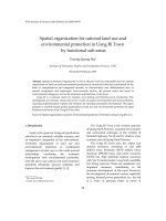
In more developed shale plays, such as the Barnett Shale,
with the use of geostatistical analysis tools, operators can
understand the potential scaling risk of a given well before
drilling commences. Figure 2 shows a map that illustrates the
AADE-10-DF-HO-08 Critical Considerations for Successful Hydraulic Fracturing and Shale Gas Recovery 3
scaling risks for barium sulfate and strontium sulfate in
Barnett Shale wells. From the information gathered,
presumptions can be made regarding scaling risks in a
particular location, and scale inhibitor rates can be adjusted
accordingly to ensure that the appropriate amount and type of
scale inhibitor is present during the fracturing process and the
flowback period before production scale inhibitor application
begins.
Flow-Stimulator Additive
Surfactants are used in the frac fluid to lower capillary
forces to assist in the recovery of the injected fluid during the
production phase. Without proper screening of these
molecules, surfactants can be selected that adsorb on to the
fracture surfaces and cause phase trapping. The net effect of
phase trapping is reduced fracture permeability and reduced
production.
Laboratory testing has shown that microemulsion blends of
surfactants increase frac fluid flow-back in tight shale gas
reservoirs and lowers the pressure required for flowback
10
.
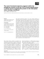
Another one of the important characteristics of these fluids is
their low interfacial tension
11
. Low interfacial tension is
critical because these interfacial forces are maintained as the
frac fluid enters the fracture spaces and when flowback
begins, the inherent mobility of the fluid is high. Figure 3
illustrates the low interfacial tension properties of a blend of
two dissimilar fluids, a microemulsion fluid and a heavy crude
oil.
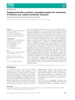
Another necessary characteristic of the frac fluid design is
that it should lower surface tension properties between the
shale surface and the produced gas. The treatment levels of
this additive are low due to costs and thus, must exhibit low
surface tension properties in the ppm range. Figure 4 is a
graph of measured surface tension values at various low ppm
levels. Note that even at 10 ppm of active product, the surface
tension is similar to the surface tension measured at higher
ppm (e.g. 500, 200, 100, etc.).
Laboratory Studies
Bacterial Control
To determine the optimum biocide program for treating the
fracturing fluid bacterial populations, planktonic bacterial kill
studies were performed on several different chemically free
frac water sources
12
. The test involved inoculation of the water
with previously cultured indigenous bacteria, weighing out the
water into clean 6-oz glass prescription bottles, and dosing
with biocides at various concentrations. In addition, a control
sample with only indigenous bacteria was prepared. The
analysis exposed the bacteria in each sample to the biocides
for various contact times, such as 1 hour, 24 hours, 1 week and
3 weeks. The longer contact times simulated the fracturing
fluid water that is retained by the reservoir following the
flowback period.
At each contact time period, the serial dilution technique
was used to enumerate the surviving bacteria in each biocide-
treated and control sample. The acid-producing bacteria
(APB) enumeration used samples diluted into a freshwater
phenol red dextrose medium, while the sulfate-reducing
bacteria (SRB) enumeration used samples diluted into a
freshwater proprietary SRB medium. To simulate downhole
conditions, the serially diluted culture vials were incubated for
28 days at 95º F. A six-vial serial dilution was inoculated for
the biocide-treated samples and an eight-bottle serial dilution
series was used for the control samples.
Following the 28-day incubation period, the results of the
kill study were tabulated and the 1-hour and 24-hour contact
time results are reported in Figure 4. The results showed that
Biocide A at 75 ppm and Biocide C at 150 ppm provided an
eight-log reduction in both the APB and SRB concentrations
as compared to the untreated control. Upon consideration of
product price, Biocide A at 75 ppm was deemed to be the most
cost-effective bacterial control program for this frac water
source.
Lubricity (Friction Reduction)
Comprehensive laboratory evaluations of friction reducers
will evaluate the effect of pH, temperature, salinity and other
frac additives on the drag-reduction capabilities and dispersion
speed. The temperature, salinity and pH tolerance range of a
friction reducer can be established through the use of a
dynamic flow loop apparatus as described by P. Kaufmen et
al
8
. Figure 5 illustrates the brine tolerance range of an anionic
friction reducer.
In order to eliminate incompatibility-related pressure risks,
extensive laboratory evaluations of product compatibility must
be carried out with the use of flow loop studies (Figure 6),
biocide kill studies and scale inhibition tests. By evaluating
the performance of each additive in the presence of the other
additives, it is possible to quantify any potential negative or
positive interactions.
Scale Inhibition
Laboratory evaluations of frac scale inhibitors require
rigorous replication of the dynamic conditions both in the
early stages of the fracturing process and the late stages of the
flow-back. Dynamic scale tube block tests allow for accurate
analysis of scale inhibitors under system pressure and
temperature, providing results that are not possible with static
tests
13
.
Figure 7 demonstrates the establishment of a minimum
effective concentration (MEC) of a frac scale inhibitor using
the dynamic scale tube block method under system conditions.
By using geostatistical software in combination with the MEC
results, the optimal loading rate can be established to provide
seamless scale inhibition for all phases of completion and
production.
Case Histories
Bacterial Control
A Barnett Shale operator was experiencing a high number
of microbially induced corrosion failures in their gathering
system flowlines and biogenic hydrogen sulfide gas
production in their production wells and produced water
storage tanks. These bacterially associated issues created a
4 J. Fichter, G. Grawunder, A. Bui, and T. Jones AADE-10-DF-HO-08
risk of negative environmental impact and potential for
personal injury. A detailed microbiological survey of the
fracturing process, the gas/fluid separation facilities and the
gathering system was performed to identify the source of these
issues. Results for a representative wellsite survey are shown
in Figure 5. The survey concluded that the source well water
used for fracturing was contaminated with high levels of acid-
producing and sulfate-reducing bacteria (typically 10
4
to >10
6
APB and SRB/mL (Figures 8, 9 and 10).
The incumbent microbiocide program for the frac water
was ineffective, resulting in contamination of the production
wells during the frac job and subsequent contamination of the
downstream portions of the system as the fracturing fluid was
flown back and the well was put on production. The
representative planktonic kill study on the frac water (Figure
11) indicated that Biocide A at 50 to 75 ppm would be the
most cost-effective biocide for treating the frac water. The
biocide was injected at 60 ppm “on the fly” into the blender
with a dedicated frac chemical injection truck.
Monitoring frac water samples were collected just prior to
pumping the frac job to determine the background
concentration of bacteria. Following the frac jobs, additional
samples were collected from the production wellhead to
determine the surviving concentration of bacteria. Samples
were collected within 10 days following the frac job (early
flowback), 30 days, 60 days and 90 days post-frac. A target
bacterial concentration of ≤10
3
bacteria/mL was set as the
performance target for the biocide program. The early
flowback results for 70 wells treated with 60 ppm Biocide A
demonstrated that 95% of the wells treated had bacterial
concentrations within the target specification (Figure 11).
Friction Reduction
An operator producing in the Barnett Shale had been
experiencing pressure problems during frac jobs leading to
higher horsepower requirements, longer pumping times and
added expense. The issue traced back to frac additive
incompatibility issues between the friction reducer and other
crucial additives. Because these operators were sourcing
additives both from the frac pumping company and a chemical
service provider, there was no effective way to predict or
address chemical incompatibilities. The operator sought a
single supplier that could provide a complete range of high-
performing and compatible additives in order to reduce costs
and bring wells online sooner.
Fit-for-purpose product and service recommendations were
provided based on water chemistry, measured bacterial
populations and reservoir pressures. Full laboratory support
was deployed to ensure product compatibility before any
chemical was applied. Through careful product selection and
application optimization, the operator enjoyed a 5 to 10%
reduction in friction reducer injection rates relative to prior
frac jobs (often getting effective results at rates less than 0.25
gallons per thousand, Figure 12) Biocide injection and scale
inhibitor rates were also optimized resulting in significant cost
savings to the operator. Most importantly, compatibility
testing ensured that neither the biocide nor the scale inhibitor
retarded the performance of the friction reducer (Figure 13).
As a result, the operator was able to safely overcome and
stabilize reservoir pressure spikes and maintain high rates of
injection.
Scale Inhibition
An operator in the Barnett Shale was experiencing
increasing reports of plugged or restricted tubing within the
first 30 days of production. Laboratory analysis of the solids
indicated deposition of barium sulfate and strontium sulfate.
Through careful monitoring of produced water after the
fracturing process, it is possible to determine the effectiveness
of a scale inhibition program. Figure 14 demonstrates the
scaling tendencies typically experienced in the Barnett Shale
over the first five months. As seen in the graph, the sulfate
that was introduced via the frac source water declined rapidly,
but the increasing salinity and barium in the produced water
created a significant scaling potential for barium sulfate while
the sulfate was still in the well, which was 15 days post-frac
for this well. From this example, there was enough scale
inhibitor present above its minimum effective concentration to
prevent barium sulfate formation. Through the use of the
geostatistical predictive tools and laboratory analyses, costly
mineral scale deposition can be prevented.
Flow-Stimulator Additive
An operator in East Texas completed several hydraulically
fractured wells located within a half-mile radius. One well
was treated with a Flow-Stimulator Additive during the
fracturing process and compared with wells that were not.
From the operator’s perspective, the Flow-Stimulator Additive
has significantly increased the total production volume, by
144% and 141%, based on 30 and 60 days of production,
respectively. Because of its ability to improve water flow-
back, solubilize emulsions and sustain total production,
several hundred of barrels of incremental oil were also
realized during the first 60 days of production.
Conclusions
Hydraulic fracturing using slick water is a common
mechanism to convert low permeability shale gas reservoirs
into commercial assets. During the planning stages of the
fracturing process, it is important for operators to think long-
term and consider the impact the fracturing process might
have on the day-to-day operations once the wells have been
brought on production. Planning and coordinating services
and designing multi-functional frac fluids are critical elements
for project success.
Critical to determining the essential frac fluid additives is
an up-front project survey and system evaluation to anticipate
the operational issues that may arise due to the fracturing
process and determine the appropriate service and chemical
options required for a low-risk, safe and productive fracturing
operation.
Once the field survey is complete and the fracturing
process and system operations are well understood, another
essential step in designing a fit-for-purpose frac additive
program for an operator is to perform detailed laboratory
AADE-10-DF-HO-08 Critical Considerations for Successful Hydraulic Fracturing and Shale Gas Recovery 5
evaluations for product selection, mimicking system
conditions as closely as possible. For scale inhibitor product
selection, dynamic scale tube block tests allow for rigorous
replication of the dynamic conditions occurring in the early
stages of the fracturing process and the late stages of the flow-
back, allowing for duplication of the system pressure and
temperature. Flow loop testing under system conditions will
allow for determination of the optimum friction reducer
chemistry and loading rate for reducing hydraulic friction.
Laboratory testing allows for determination of the optimum
microemulsion surfactant blends for increasing fracture fluid
flow-back in tight shale gas reservoirs and lowering the
pressure required for flow-back. Planktonic bacterial kill
studies should be performed using representative system
waters for selection of the most cost-effective bacterial control
program. Once all the frac additives and loading rates have
been determined, it is imperative to ensure that all the frac
fluid components are compatible with each other, the frac
water itself, the production chemicals and the formation
material to avoid issues during the fracturing process, flow-
back period and production cycles of the well.
An aggressive monitoring program is instrumental in
assessing the performance of the frac chemical program.
However, collection of the data is not enough. It is so
important to take the time to learn from the information gained
from the monitoring program and use the data to optimize the
chemical program and assess system conditions that would
require an adjustment of the chemical loading rate.
Finally, an integrated chemical program from the
fracturing through production will ensure a seamless transition
and comprehensive risk management program throughout the
life of the well.
References
1. Howard, G.C. and C.R. Fast (editors), “Hydraulic Fracturing,
Monograph Vol. 2 of the Henry L. Doherty Series,” SPE 027,
New York, 1970.
2. Hayden, J., and D. Pursell, D. Pickering Energy Partners Inc.
The Barnett Shale. Visitors Guide to the Hottest Gas Play in the
US, /, October 2005.
3. Energy Information Administration, Is U.S. Natural Gas
Production Increasing? Energy in Brief, June 2008.
4. EPA. Drinking Water Academy (DWA). Introduction to the
Underground Injection Control Program, January 2003.
5. EPA. US EPA's Program to Regulate the Placement of Waste
Water and other Fluids Underground. EPA 816-F-04-040, June
2004.
6. Schlumberger Fracturing Services PowerSTIM, www.slb.com,
September, 2008.
7. J. Fichter, K. Johnson, K. French, R. Oden. “Use of
Microbiocides in Barnett Shale Gas Well Fracturing Fluids to
Control Bacterially Related Problems,” NACE 1703, NACE
Corrosion New Orleans, LA., March 16-20, 2008.
8. P. Kaufman, G.S. Penny, and J. Paktinat., “Critical Evaluations
of Additives Used in Shale Slickwater Fracs,” SPE 119900, SPE
Shale Gas Production Conference, Fort Worth, TX, 16-18
November,2008.
9. S.M. Rimassa, P.R. Howard, M.O. Arnold. “Are You Buying
Too Much Friction Reducer Because of Your Biocide?” SPE
119569-MS, SPE Hydraulic Fracturing Conference, The
Woodlands, TX, January 19-21, 2009.
10. J. Paktinat, A. Pinkhouse, N. Johnson, C. Williams, G. Lash, G.
Penny and D. Goff. “Case Study: Optimizing Hydraulic
Fracturing Performance in Northeastern United States Fractured
Shale Formations,” SPE 104306, SPE Eastern Regional
Meeting, Canton, Ohio, 11-13 October, 2006.
11. R. Peresich, T. Jones, L. Quintero, T. Gardin. “Case Studies of
Mesophase Technology Employed for the Remediation of Case
Hole Completions,” NTCE 18-01, AADE Annual Conference
and Exhibition, New Orleans, LA., 2009.
12. NACE Standard TM- 0194-04 Field Monitoring of Bacterial
Growth in Oilfield Systems, 2004.
13. M.D. Yuan, E. Jamieson, P. Hammong, Baker Petrolite,
Investigation of Scaling and Inhibition Mechanisms and the
Influencing Factors in Static and Dynamic Inhibition Tests
6 J. Fichter, G. Grawunder, A. Bui, and T. Jones AADE-10-DF-HO-08
Figures
Figure 1 Shale gas plays in the United States
Figure 2 Sulfate scaling risks in the Barnett Shale
Figure 3Surface tension of microemulsion in KCl brine
AADE-10-DF-HO-08 Critical Considerations for Successful Hydraulic Fracturing and Shale Gas Recovery 7
Figure 4 IFT of flow-stimulator additive in crude oil
Figure 5
Effect of salinity on anionic friction reducer
Figure 6 Effect of biocide and scale inhibitor on anionic
friction reducer
Figure 7 Dynamic scale tube block testing of scale
inhibitor
Figure 8 Microbiological survey results for a
representative wellsite
Figure 9 Microbiological survey results for
representative fracturing water sources
Figure 10 Photomicrographs of representative
fracturing water sources
Effect of Sodium Chloride on Friction Reduction
0.00%
5.00%
10.00%
15.00%
20.00%
25.00%
30.00%
35.00%
40.00%
45.00%
50.00%
2 2.5 3 3.5 4 4.5 5 5.5 6
Velocity (fps)
% Drag Reduction
tap water
0.5% NaCl
1% NaCl
2% NaCl
4% NaCl
6% NaCl
Effect of Biocide and Scale Inhibitor on Anionic Friction Reducer
40.00%
45.00%
50.00%
55.00%
60.00%
65.00%
70.00%
75.00%
024681012
Velocity (fps)
% Drag Reduction
15:3:1 FR:Biocide:Scale Inhibitor ratio
33:3:1 FR:Biocide:Scale Inhibitor ratio
60:3:1 FR:Biocide:Scale Inhibitor ratio
FR Only (Control)
Bacterial Culture Media
Sample Location
Microscopy
(Bacteria/mL)
APB/mL SRB/mL
Source Well 2 X 10
5
10
5
BD
Frac Pit 7 X 10
6
≥ 10
6
10
2
Wellhead 3 X 10
5
10
4
10
2
Separator 2 X 10
6
≥ 10
6
10
3
Produced Water Storage
Tank
2 X 10
7
≥ 10
6
≥ 10
6
BD = bacterial concentrations are below the detection limit of the assay (< 1 bacteria/mL)
Microscopic Analysis Bacterial Culture Media
Sample ID
Bacteria/mL
Algae/mL APB/mL SRB/mL
Water Quality
Pond #1 5 X 10
6
occasional ≥ 10
6
10
4
Tan water with
solids; natural
stock pond
Lined Pit #1 9 X 10
6
BD ≥ 10
6
10
3
Opaque water
Pond #2 2 X 10
6
3.4 X 10
4
≥ 10
6
10
4
Opaque water
Pond #3 4 X 10
5
occasional 10
5
10
2
Opaque water
Lined Pit #2 9 X 10
7
BD ≥ 10
6
≥ 10
6
Black water;
lot of sediment
Lined Pit #3 3 X 10
5
BD 10
5
10
2
Clear water
Lined Pit #4 3 X 10
7
BD ≥ 10
6
≥ 10
6
Dark brown
water
BD = below detectable limits
8 J. Fichter, G. Grawunder, A. Bui, and T. Jones AADE-10-DF-HO-08
Figure 11 Representative planktonic kill study results
Figure 12 Flowback monitoring results for 70 production
wells where fracturing fluid was treated with 60 ppm
Biocide A. Results expressed as number of positive
culture media bottles in a serial dilution series.
Figure 13 Friction reductions during fracturing process
Figure 14 Scaling tendencies in first five months of
production
One Hour Contact Time 24 Hours Contact Time
Biocide
Concentration
(ppm)
APB SRB APB SRB
30 10
5
10
5
10
5
BD
50 10
3
BD 10
2
BD
75 BD BD BD BD
Biocide A
100 BD BD BD BD
50 ≥ 10
6
≥ 10
6
≥ 10
6
≥ 10
6
100 ≥ 10
6
10
4
10
5
≥ 10
6
150 10
5
10
3
10
4
10
4
Biocide B
200 10
2
10
2
10
2
10
2
50 10
5
10
5
10
5
10
2
100 10
2
BD 10
3
BD
150 BD BD BD BD
Biocide C
200 BD BD BD BD
30 ≥ 10
6
≥ 10
6
≥ 10
6
≥ 10
6
50 ≥ 10
6
≥ 10
6
≥ 10
6
≥ 10
6
75 ≥ 10
6
≥ 10
6
≥ 10
6
≥ 10
6
Biocide D
100 ≥ 10
6
≥ 10
6
≥ 10
6
≥ 10
6
25 ≥ 10
6
≥ 10
6
≥ 10
6
≥ 10
6
50 ≥ 10
6
≥ 10
6
≥ 10
6
≥ 10
6
Biocide E
100 ≥ 10
6
≥ 10
6
10
4
10
4
25 ≥ 10
6
≥ 10
6
≥ 10
6
≥ 10
6
50 ≥ 10
6
≥ 10
6
≥ 10
6
≥ 10
6
Biocide F
100 ≥ 10
6
≥ 10
6
10
5
10
3
Untreated Control 10
8
10
8
10
8
10
8
*Results are expressed as number of positive bottles in a serial dilution series; a 9
bottle series was inoculated for the untreated control; a 6 bottle series was inoculated for
all treated samples.
≥ 10
6
= all 6 bottles in the serial dilution series were
p
ositive.
Acid-Producing Bacteria
3%
5%
15%
77%
Sulfate-Reducing Bacteria
10%
2%
88%
0
1
2
3
4
5
6
Friction Reduction
1500
1750
2000
2250
2500
2750
3000
3250
3500
6
:
1
8
6
:
1
9
6:21
6:23
6:24
6
:
2
6
6
:
2
8
6:29
6:31
6:33
6
:34
6:36
6:38
6:39
6:41
6
:43
6
:
4
4
6
:
4
6
6:48
6
:49
6
:
5
1
Time
Pressure (PSI)
0
0.1
0.2
0.3
0.4
0.5
0.6
0.7
0.8
0.9
1
FR Loading Rate
(gallons per
thousand/gpt)
Pressure (PSI)
FR Loading Rate (GPT)
Frac Flowback Water Analysis
0
50
100
150
200
250
300
350
400
450
0 30 60 90 120 150
Days
ppm
0
200
400
600
800
1000
1200
Chloride (mg/L/200)
Barium (mg/l)
Sulfate (mg/l)
SI Residual (ppm)
Day
BaSO4
Saturation
Index
Predicted BaSO4
Amount
(lbs/1000bbls)
0 2.3 78.2
15 2.67 254.1
30 2.51 172.1
45 2.56 124.1