getting started with msp430
Bạn đang xem bản rút gọn của tài liệu. Xem và tải ngay bản đầy đủ của tài liệu tại đây (80.07 KB, 28 trang )
July 1999 Mixed-Signal Products
User’s Guide
SLAU028
IMPORTANT NOTICE
Texas Instruments and its subsidiaries (TI) reserve the right to make changes to their products or to discontinue
any product or service without notice, and advise customers to obtain the latest version of relevant information
to verify, before placing orders, that information being relied on is current and complete. All products are sold
subject to the terms and conditions of sale supplied at the time of order acknowledgement, including those
pertaining to warranty, patent infringement, and limitation of liability.
TI warrants performance of its semiconductor products to the specifications applicable at the time of sale in
accordance with TI’s standard warranty. Testing and other quality control techniques are utilized to the extent
TI deems necessary to support this warranty. Specific testing of all parameters of each device is not necessarily
performed, except those mandated by government requirements.
CERTAIN APPLICATIONS USING SEMICONDUCTOR PRODUCTS MAY INVOLVE POTENTIAL RISKS OF
DEATH, PERSONAL INJURY, OR SEVERE PROPERTY OR ENVIRONMENTAL DAMAGE (“CRITICAL
APPLICATIONS”). TI SEMICONDUCTOR PRODUCTS ARE NOT DESIGNED, AUTHORIZED, OR
WARRANTED TO BE SUITABLE FOR USE IN LIFE-SUPPORT DEVICES OR SYSTEMS OR OTHER
CRITICAL APPLICATIONS. INCLUSION OF TI PRODUCTS IN SUCH APPLICATIONS IS UNDERSTOOD TO
BE FULLY AT THE CUSTOMER’S RISK.
In order to minimize risks associated with the customer’s applications, adequate design and operating
safeguards must be provided by the customer to minimize inherent or procedural hazards.
TI assumes no liability for applications assistance or customer product design. TI does not warrant or represent
that any license, either express or implied, is granted under any patent right, copyright, mask work right, or other
intellectual property right of TI covering or relating to any combination, machine, or process in which such
semiconductor products or services might be or are used. TI’s publication of information regarding any third
party’s products or services does not constitute TI’s approval, warranty or endorsement thereof.
Copyright 1999, Texas Instruments Incorporated
Information About Cautions and Warnings
iii
Read This First
Preface
Read This First
About This Manual
This document describes the procedures for how to get started using the
MSP430 controller, hardware, and simulator. It looks at code and explains
running out of RAM, debugging with HyperTerminal, and programming the
MSP430 EPROM.
The manual assumes that you have set up the Windows operating environ-
ment and that you are familiar with the basic terminology and procedures for
using Microsoft Windows. To set up Windows or review basic Windows infor-
mation, see your Windows documentation.
How to Use This Manual
This document contains the following chapters:
Chapter 1 Getting Started With the MSP430 Controller
Chapter 2 Getting Started With the Hardware
Chapter 3 Using the Simulator
Chapter 4 The MSP430 Code
Chapter 5 Running Out of RAM and Debugging with HyperTerminal
Chapter 6 Programming the MSP430 EPROM
Information About Cautions and Warnings
This book may contain cautions and warnings.
This is an example of a caution statement.
A caution statement describes a situation that could potentially
damage your software or equipment.
This is an example of a warning statement.
A warning statement describes a situation that could potentially
cause harm to you
.
Related Documentation From Texas Instruments
iv
The information in a caution or a warning is provided for your protection.
Please read each caution and warning carefully.
Related Documentation From Texas Instruments
MSP430 Family Architecture Guide and Module Library,
1996, SLAUE10B
MSP430 Application Report,
1998, SLAAE10C
Data Sheet MSP430x11x, 1999, SLAS196A
Data Sheet MSP430x31x, 1999, SLAS165C
Data Sheet MSP430x32x, 1999, SLAS219
Data Sheet MSP430x33x, 1998, SLAS163
MSP430 Family STK/EVK Manual,
(releasing) 1999, SLAS191
MSP430 Simulation Manual,
(releasing) 1999, SLAA055
MSP430 LCD–Editor Manual
,
(releasing) 1999, SLAU027
MSP430 Family Software User’s Guide
1994, SLAUE11
MSP430 Family Assembly Language Tools User’s Guide
, 1994, SLAUE12
MSP430 Family Programming Adapter Manual
,
(releasing) 1999, SLAU026
Running Title—Attribute Reference
v
Chapter Title—Attribute Reference
Contents
1 Getting Started With the MSP430 Controller 1-1. . . . . . . . . . . . . . . . . . . . . . . . . . . . . . . . . . . . . . .
1.1 Getting Started 1-2. . . . . . . . . . . . . . . . . . . . . . . . . . . . . . . . . . . . . . . . . . . . . . . . . . . . . . . . . . . . .
2 Getting Started With the Hardware 2-1. . . . . . . . . . . . . . . . . . . . . . . . . . . . . . . . . . . . . . . . . . . . . . . .
2.1 The LCD 2-2. . . . . . . . . . . . . . . . . . . . . . . . . . . . . . . . . . . . . . . . . . . . . . . . . . . . . . . . . . . . . . . . . .
2.2 The EPROM versus OTP Devices 2-2. . . . . . . . . . . . . . . . . . . . . . . . . . . . . . . . . . . . . . . . . . . .
2.3 Connecting the Hardware 2-2. . . . . . . . . . . . . . . . . . . . . . . . . . . . . . . . . . . . . . . . . . . . . . . . . . . .
3 Using the Simulator 3-1. . . . . . . . . . . . . . . . . . . . . . . . . . . . . . . . . . . . . . . . . . . . . . . . . . . . . . . . . . . . .
4 The MSP430 Code 4-1. . . . . . . . . . . . . . . . . . . . . . . . . . . . . . . . . . . . . . . . . . . . . . . . . . . . . . . . . . . . . . .
5 Running Out of RAM and Debugging with HyperTerminal 5-1. . . . . . . . . . . . . . . . . . . . . . . . . . .
6 Programming the MSP430 ROM 6-1. . . . . . . . . . . . . . . . . . . . . . . . . . . . . . . . . . . . . . . . . . . . . . . . . .
6.1 Programming on the STK/EVK 6-2. . . . . . . . . . . . . . . . . . . . . . . . . . . . . . . . . . . . . . . . . . . . . . .
6.1.1 Programming a Blank OTP or EPROM 6-2. . . . . . . . . . . . . . . . . . . . . . . . . . . . . . . . .
6.1.2 Resetting the STK Monitor Code to a Specified Program 6-2. . . . . . . . . . . . . . . . .
6.1.3 Resetting the EVK Monitor Code to a Specified Program 6-4. . . . . . . . . . . . . . . . .
6.2 Programming on Another Target Board 6-7. . . . . . . . . . . . . . . . . . . . . . . . . . . . . . . . . . . . . . . .
Running Title—Attribute Reference
vi
Acknowledgement
Many thanks to Richard Baker, Mark Buccini, Brian Merritt, John Morgan and
Dale Wellborn for their support with this user’s guide.
1-1
Getting Started With the MSP430 Controller
Getting Started With the MSP430 Controller
This user’s guide is intended as an
easy-to-use
guide for the MSP430 family.
The designer should use this manual with the references cited throughout the
document. This is not intended to be a standalone document for the MSP430
family.
The documentation for the MSP430 family is written for use with any MSP430
family members. The manuals contain sections and pinouts for future growth
of the product line. Refer to the datasheet that corresponds to the MSP430
family member being used to be sure of the correct pinout, number of ADC
channels, number of LCD segments, and peripheral set.
This manual will show how to assemble source files from within the assembler.
These files will then be run on the simulator to demonstrate the correct
operation; then the files will be downloaded to the target hardware and run.
This manual refers to HyperTerminal and monitor programs. The
HyperTerminal program was written by Hilgraeve and is included with
Microsoft Windows. The monitor program, RS-232 software written by Texas
Instruments, allows the HyperTerminal program to communicate and
download files to the MSP430 parts.
Topic Page
1.1 Getting Started 1–2. . . . . . . . . . . . . . . . . . . . . . . . . . . . . . . . . . . . . . . . . . . . . . .
Chapter 1
Getting Started
1-2
1.1 Getting Started
If you are already familiar with embedded systems and evaluation boards, fol-
low these steps; otherwise begin with Chapter 2.
1) If you have an EVK, solder the LCD in place (refer to the LCD section for
the orientation for soldering) and place the labeled UVEPROM in the sock-
et. An STK comes with the OTP part already soldered on and the LCD
installed.
2) Plug one end of the ribbon cable into the board and the other end into the
COM port of the computer.
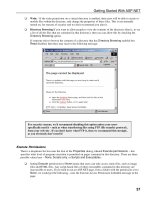
3) Install the software by running
setup.exe
on the Development Tools Disk
1 and following the instructions.
4) Start the simulator by double clicking on the Simulation Environment icon.
5) Follow the steps outlined in the
Simulation Environment and LCD–Editor
Manual
in Chapter 3 that explain how to open, configure, and build a proj-
ect file. To enable the LCD simulation environment click on Options/LCD
setup, then be sure that the filename c:\adt430\dt430\examples\demo.lcd
is in the window, unless another file is desired. Click on ok then go to the
Window/LCD button and click on LCD.
6) After you have completed debugging the program using the simulator, be
sure to go to Options/Project/Assembler (See the Options Menu in the
Simulation Environment and LCD-Editor
Manual
) and be sure that the
Generate Text Object file box is checked. Generate a *.txt file by using the
Project/Rebuild All button.
7) The program may then be either tested using HyperTerminal to
download and run out of RAM or programmed directly in the EPROM of
the part using the MSP430 programing adapter and executed. For
instructions on using HyperTerminal, refer to the
Starter Kit/Evaluation Kit
Manual
.
Once the OTP (one time programmable) has had the program
downloaded to the ROM, it may not be programmed again.
8) There are three ways to program the MSP430 EPROM parts.
1) To program the MSP430 EPROM, click on the Programming Adapter
icon for the EVK or follow the instructions given in the
Starter
Kit/Evaluation Kit Manual
for the STK in the Chapter
The Identification
Bit Pattern AA55h
. Programming Adapter instructions are located in
the MSP430 Family Programming Adapter Manual
.
2) Using the serial port. Refer to
STK/EVK Manual
3) Using third party vendor tools
Getting Started
1-3
Getting Started With the MSP430 Controller
Note:
The programmer can use third party vendor tools to debug and program the
MSP430 parts. Refer to the TI MSP430 website for a complete list of these
vendors and links to their website. This website also contains software and
application reports that are downloadable at
/>
1-4
2-1
Getting Started With the Hardware
Getting Started With the Hardware
Refer to the
Starter Kit/Evaluation Kit Manual
appendix,
Difference Between
STK and EVK
. The included table shows what the differences are between the
kits.
Topic Page
2.1 The LCD 2–2. . . . . . . . . . . . . . . . . . . . . . . . . . . . . . . . . . . . . . . . . . . . . . . . . . . . . .
2.2 The EPROM Versus OTP Devices 2–2. . . . . . . . . . . . . . . . . . . . . . . . . . . . . . .
2.3 Connecting the Hardware 2–2. . . . . . . . . . . . . . . . . . . . . . . . . . . . . . . . . . . . . .
Chapter 2
The LCD
2-2
2.1 The LCD
If no LCD is needed for the application, this step may be omitted. The LCD will
not be installed when you receive your EVK board so that the board can be
used with another vendor’s LCD. The user must solder the LCD in place.
Solder the LCD so that it hangs over the PC board, not hanging off of the PC
board as shown in the
Starter Kit/Evaluation Kit Manual
in the section
STK/EVK Connectors
. Use spacers placed on the backside of the LCD while
soldering it onto the board.
2.2 The EPROM versus OTP Devices
The STK kits include an OTP device that has been soldered onto the board.
The EVK kits come with two UV erasable EPROM devices. A monitor program
has already been downloaded into one of the EPROM devices (indicated by
a label covering the window) and the OTP device. The second EPROM device
is blank. The EPROM device that contains the monitor code should be placed
so the notched corner of the EPROM is located in the notched corner of the
socket.
If the EPROM containing the monitor code is accidentally erased, the
monitor program needs to be reloaded. Refer to the Starter
Kit/Evaluation Kit Manual in the section
Program the Monitor Software
into an Erased EPROM
.
2.3 Connecting the Hardware
The STK and EVK kits each come with the necessary cabling to interface to
a computer. Connect the RS-232 ribbon cable to the COM port of the computer
(noting which COM port is being used) and the other end to the EVK/STK
board. To change the COM port being used, refer to the STK/EVK manual.
3-1
Using the Simulator
Using the Simulator
Each STK/EVK kit comes with the necessary diskettes containing the software
for the simulator. The EVK kit includes an additional diskette that contains soft-
ware for the programming adapter. Refer to the
Starter Kit/Evaluation Kit
Manual’s
Installing the Software
chapter and the
Simulation Environment and
LCD Editor Manual
Installation
chapter for information on installing this soft-
ware.
Note:
Only the EVK comes with the LCD-editor software.
Once the software has been installed, double click on the Simulation
Environment icon. To begin to use the simulator, choose a project. Refer to the
MSP430
Simulation Environment and LCD-Editor Manual Getting Started
chapter for more detailed instructions on using the simulator. The MSP430
LCD editor allows users to create custom LCDs. The software contains the file
demo. LCD configured to match the LCD that is supplied with the EVK/STK
kits. Enable the LCD simulation environment by going to Options/LCD setup.
Be sure that the file name c:\adt430\dt430\examples\demo.lcd is in the box
(unless there is another *.lcd file required that matches the LCD of choice).
After clicking ok, go to the Window/LCD button and click LCD. An LCD window
appears on the desktop.
Chapter 3
3-2
4-1
The MSP430 Code
The MSP430 Code
MSP430 STK/EVK kits contain several programs, and more code may be
obtained from either the MSP430 website or the
MSP430 Family Application
Report Book
. All code should contain at a minimum:
A memory mapping section
A setup or initialization section
The main body of code
An interrupt vector table
The STK/EVK boards are memory mapped differently between the family of
parts and the simulator. Refer to a datasheet for the program memory map for
a specific MSP430 device. An example for the MSP430x325 family is shown
below.
Int. Vector
16 kB OPT
512B RAM
16b Per.
8b Per.
SFR
FFFFh
FFE0h
FFDFh
C000h
03FFh
0200h
01FFh
0100h
00FFh
0010h
000Fh
0000h
MSP430P/E325
Int. Vector
16 kB
EPROM
512B RAM
16b Per.
8b Per.
SFR
FFFFh
FFE0h
FFDFh
03FFh
0200h
01FFh
0100h
00FFh
0010h
000Fh
0000h
MSP430C325
C000h
Int. Vector
8 kB EPROM
256B RAM
16b Per.
8b Per.
SFR
FFFFh
FFE0h
FFDFh
E000h
02FFh
0200h
01FFh
0100h
00FFh
0010h
000Fh
MSP430C323
0000h
Chapter 4
4-2
;––––––––––––––––––––––––––––––––––––––––––––––––––––––––––––––––––––––––––––
; SYSTEM DEFINITIONS FOR 320 STK/EVK
;––––––––––––––––––––––––––––––––––––––––––––––––––––––––––––––––––––––––––––
RAM_orig .set 00200h ; RAM start
EPROM_orig .set 0C000h ; 32x EPROM start
.if SIM = 1 This is the memory map for the STK
I_vectors .set 003FFh ; STK Interrupt vectors in RAM
Main .equ RAM_orig+20h ; Program RAM start address
BTload .equ 036h ; Load actual 1 second interrupt (036h)
.else
I_vectors .set 0FFFFh ; Interrupt vectors in EPROM This is the memory map for the
simulator
Stack .set 003DEh ; Stackpointer
Main .equ EPROM_orig ; Program EPROM start
BTload .equ 011h ; Load fast interrupt, NOT 1 sec.
.endif
; ************************************
; STATUS REGISTER BITS
; ************************************ Defining a few of the registers and
C .set 1H low power modes
Z .set 2H
N .set 4H
V .set 100H
GIE .set 8H
CPUOFF .set 10H
OSCOFF .set 20H
SCG0 .set 40H
SCG1 .set 80H
LPM0 .set CPUOFF
LPM1 .set SCG0+CPUOFF+GIE
LPM2 .set SCG1+CPUOFF+GIE
LPM3 .set SCG1+SCG0+CPUOFF+GIE
LPM4 .set OSCOFF+CPUOFF+GIE
;*************************************
;Watchdog definitions
;*************************************
WDTCTL .equ 120h ;WDT control register address
WDTPW .equ 5A00h ;password for WDT control register access
WDTCL .equ 8 ;bit position for WDT reset
WDTIFG .equ 1 ;bit position for WDT interrupt in SFR
WDTHOLD .equ 80h
;*************************************
;Timer definitions
;*************************************
BTCTL .equ 040h ;Basic Timer
TCCTL .equ 42h ;TC8 control register address
TCPLD .equ 43h ;TC8 preload register address
TCDAT .equ 44h ;TC8 counter address
P0_1IFG .equ 8 ;bitposition for TC8 interrupt in SFR
RXD .equ 1 ;bit position in TCCTL
TXD .equ 2 ;bit position in TCCTL
RXACT .equ 4 ;bit position in TCCTL
ENCNT .equ 8 ;bit position in TCCTL
TXE .equ 10h ;bit position in TCCTL
ISCTL .equ 20h ;bit position in TCCTL
SSEL1 .equ 40h ;bit position in TCCTL
SSEL0 .equ 80h ;bit position in TCCTL
4-3
The MSP430 Code
An additional register definition file can be found on the MSP430 website. This
file is called STD_DEF.asm and can be included in your code by using the
.in-
clude statement
. The address in the source code must be correct, depending
on what MSP430 family member you are using.
;–––––––––––––––––––––––––––––––––––––
; Mainloop
;––––––––––––––––––––––––––––––––––––– An example of the main program
.sect ”MAIN”,EPROM_orig
RESET MOV #Stack,SP ; Initialize stackpointer on the STK
; (evk = 03DEh)
SetupWDT MOV #(WDTPW+WDTHOLD)&WDTCTL ; Stop Watchdog Timer
;
Loop BIS #LPM3,SR ; Enter LPM3
User’s Code Here
; ; Users routine with interrupts here
JMP Loop ; Again
An example of the interrupt vector table is shown below. In this example an
interrupt routine is called for the basic timer.
;–––––––––––––––––––––––––––––––––––––––––––––––––––––––––––––––––––––––––––––
; Interrupt vectors
;–––––––––––––––––––––––––––––––––––––––––––––––––––––––––––––––––––––––––––––
.sect ”I_Vectors”,I_vectors–31 ; From MSP430P325 Family of ports
.word RESET ; No source
.word Int_BT ; Basic Timer
.word RESET ; no source
.word RESET ; no source
.word RESET ; Timer Port
.word RESET ; EOC from ADC
.word RESET ; no source
.word RESET ; no source
.word RESET ; no source
.word RESET ; no source
.word RESET ; Watchdog/Timer, Timer mode
.word RESET ; no source
.word RESET ; Address of UART handler
.word RESET ; P0.0
.word RESET ; NMI, Osc. fault
.word RESET ; POR, ext. Reset, Watchdog
.sect”Int_Code”,User_End–22h
.word #0aa55h ; if aa55h then User_Start
.end ;
4-4
5-1
Running Out of RAM and Debugging with HyperTerminal
Running Out of RAM and Debugging with
HyperTerminal
Once a program works error free on the simulator, it is downloaded to the RAM
via HyperTerminal. To download a file, create a *.txt file. To create *.txt file using
the simulator, go to Options/Project/Assembler (see the
Options Menu
in the
Simulation Environment and LCD–Editor Manual
) and be sure that the
Generate Text Object File box is checked. Generate a *.txt file by using the
Project/Rebuild All button.
Prior to running HyperTerminal, connect the STK/EVK board to the COM port
of the computer. Double click on the MSP430 Terminal icon. MSP430 should
be displayed on the LCD of the STK/EVK board and MSP–EVK430x320 or
MSP–STK430x320 should echo back to the HyperTerminal (the revision letter
may be B, C or higher). If neither event happens, ensure that the computer’s
serial port is supplying enough current. Perform the following steps to correct
this problem:
1) Check the cable connections.
2) If you receive back an unreadable message, your computer is probably
not capable of supplying enough current for the MSP430 board. Jumper
two locations on the STK/EVK board down to 3 V. Refer to the STK/EVK
Manual in the section labeled
STK/EVK Target Connectors
for the correct
jumper configuration.
3) If Step 2 does not work, attach a 9 V battery to the BAT+ and BAT– jumper
holes located on the edge of the board. (See the schematic in the
Starter
Kit/Evaluation Kit Manual
).
4) If neither Step 2 nor Step 3 works, ensure you have the correct version of
HyperTerminal. HyperTerminal that comes with Windows ’98 is suspect.
Download Windows ’95 HyperTerminal.exe and HyperTerminal.dll files
and retry this procedure.
Chapter 5
5-2
After communication between the STK/EVK and computer has been estab-
lished, double click on the MSP430 Terminal icon. Use the Transfer/Send Text
File to transfer the .txt file. Typing an
h
at any time prints a help file. Refer to
the
Starter Kit Evaluation Kit Manual
for complete instructions on using Hyper-
Terminal including setting breakpoints, viewing and modifying registers and
memory locations, etc.
6-1
Programming the MSP430 EPROM
Programming the MSP430 EPROM
The user may program the MSP430 family of parts using either:
The EVK board
The STK board
A target board that has been manufactured by the user
One of the third party vendor’s programming units (see our website for a
list of the third party vendors)
Topic Page
6.1 Programming on the STK/EVK 6–2. . . . . . . . . . . . . . . . . . . . . . . . . . . . . . . . .
6.2 Programming on Another Target Board 6–7. . . . . . . . . . . . . . . . . . . . . . . . .
Chapter 6
Programming on the STK/EVK
6-2
6.1 Programming on the STK/EVK
The
Starter Kit Evaluation Kit Manuals
contain procedures for programming
using the STK/EVK. Detailed instructions on connectors, power supplies and
software are also given. Refer to these manuals for the complete instructions.
6.1.1 Programming a Blank OTP or EPROM
Perform the following steps to program a blank chip (so that it resets to your
program).
1) Set up the code so that it is located in EPROM.
.sect ”MAIN”,08000h ; make it an EPROM location, here it is
; 8000 for a 337, use C000 for a 325
It is possible to program the RAM because RESET does not affect the RAM
contents, but this is less useful, since the program will be lost when power is
removed.
2) Set up the POR (power on reset) interrupt vector to jump to your code.
RESET
;––––––––––––––––––––––––––––––––
; place the body of your code here
;––––––––––––––––––––––––––––––––
; set up the reset vector to jump to your code
.sect ”onreset”,0FFFEh
.word RESET ; here RESET is a label at the start of
; your code
3) Program the chip with the JTAG interface. You cannot program it by the
serial port, since there is no monitor software installed.
6.1.2 Resetting the STK Monitor Code to a Specified Program
For an EVK follow the above steps to have it reset to a program. For an STK
perform the following.
1) Set up your program so that it resides in EPROM.
; before the body of code move it to EPROM
.sect”MAIN”,0C000h ; make it an EPROM location, here it is
; C000 for a 325, use 8000 for a 337
2) Set up the replacement vector table at E9E0h and the identifier AA55h at
E9DEh. The identifier must be the last item in your code. Once the STK
is programmed, the monitor (and the serial port with it) will stop.
Programming on the STK/EVK
6-3
Programming the MSP430 EPROM
The code will look similar to the following example (the exact implementation
depends on what interrupts you want to use.) A detailed table of the interrupt
vectors is given in the software section.
; before the body of code move it to EPROM
.sect ”MAIN”,0C000h ; make it an EPROM location, here it is
; C000 for a 325, use 8000 for a 337
;*************************************************************
; user program
;*************************************************************
.sect “our_r”,0E9E0h
.word RESET
.word RESET
.word RESET
.word RESET
.word RESET
.word RESET
.word RESET
.word RESET
.word RESET
.word RESET
.word RESET
.word RESET
.word RESET
.word RESET
.word RESET
.word RESET
.sect “ident”,0E9DEh
.word 0AA55h
.end
3) Program the memory. Since the STK does not have a JTAG port installed,
programming is done through the serial port. To program the EPROM from
the serial port, first connect a 12–20 V power supply to the power connec-
tor on the board. Ensure the power supply has the proper amperage. Next
place a jumper on terminals 13 and 14 of the JTAG port. If you are using
an STK, the jumper is already there. Then send a text file from HyperTer-
minal program to the EPROM.
If an EVK is available and you have an STK, then the following steps will work
too.
Programming on the STK/EVK
6-4
6.1.3 Resetting the EVK Monitor Code to a Specified Program
To make an EVK reset to a user program, perform the following steps:
1) Develop code for the monitor on an EVK.
2) Once the code runs as desired, make the following software changes.
; before the body of code move it to EPROM
.sect ”MAIN”,08000h ; make it an EPROM location, here it is
; 8000 for a 337, use C000 for a 325
RESET
;––––––––––––––––––––––––––––––––
; place the body of your code here
;––––––––––––––––––––––––––––––––
; set up the reset vector to jump to your code
.sect “onreset”,0FFFEh
.word RESET ; here RESET is a label at the start of your code
3) Program the EPROM of a device that contains no monitor. To program the
EPROM from the serial port, you need to first connect a 12–20 V power
supply to the power connector on the board. Make sure the power supply
has the proper amperage. Next place a jumper on terminals 13 and 14 of
the JTAG port.
4) Program the device using HyperTerminal via the serial port. The software
should look similar to the following:
a) Interrupt vectors
.sect ”our_r”,0E9E0h ; the location is important, see note below
;where it jumps EPROM location original location name of interrupt
.word RESET ;0E9E0h ; 0FFE0h ; I/O port P0
.word RESET ;0E9E2h ; 0FFE2h ; Basic Timer
.word RESET ;0E9E4h ; 0FFE4h ; I/O port P1
.word RESET ;0E9E6h ; 0FFE6h ; I/O port P2
.word RESET ;0E9E8h ; 0FFE8h ; Timer/Port
.word RESET ;0E9EAh ; 0FFEAh ; ADC
.word RESET ;0E9ECh ; 0FFECh ; UART tx
.word RESET ;0E9EEh ; 0FFEEh ; UART rx
.word RESET ;0E9F0h ; 0FFF0h ; TimerA TAIFG
.word RESET ;0E9F2h ; 0FFF2h ; TimerA CCIFG0
.word RESET ;0E9F4h ; 0FFF4h ; Watchdog Timer
.word RESET ;0E9F6h ; 0FFF6h ;
.word RESET ;0E9F8h ; 0FFF8h ; P0IFG.1
.word RESET ;0E9FAh ; 0FFFAh ; P0IFG.0
.word RESET ;0E9FCh ; 0FFFCh ; NMI, oscillator
.word RESET ;0E9FEh ; 0FFFEh ; powerup reset,external
; reset Watchdog
Programming on the STK/EVK
6-5
Programming the MSP430 EPROM
0E9E0h is the location for the first interrupt. If an error is detected and the
interrupts need to be redone, the table should be moved down in memory by
022h (so the second attempt will be at 0E9BEh) and the identifier in 0E9DEh
should be overwritten with 00h. Next, a new identifier is placed 022h below the
original identifier, which will now be 0E9BCh. These steps can be repeated
(memory permitting) since the monitor will look for the identifiers 0FFFFh,
0000h, and 0AA55h. If address 0E9DEh contains a 0FFFFh, then the monitor
starts normally. If address 0E9DEh contains a 0AA55h, then the program will
use the vectors immediately above. If address 0E9DEh contains a 0000h, the
program will move down by 022h and look for another identifier.
The memory map:
FFFEh
Monitor
EA00h
E9FEh
reset atchdog
E9FEh
E9FCh
rese
t
, wa
t
c
hd
og
NMI oscillator
E9FCh
E9FAh
NMI
, osc
ill
a
t
or
Dedicated I/O P0IFG 0
E9FAh
E9F8h
Dedicated
I/O
P0IFG
.
0
Dedicated I/O P0IFG.1
E9F8h
E
9
F
6
h
Dedicated
I/O
P0IFG
.
1
E9F6h
E9F4h Watchdo
g
Timer
E9F4h
E9F2h
Watchdog
Timer
TimerA CCIFG0
E9F0h TimerA TAIFG
E9EEh UART rx
E9ECh UART tx
E9EAh
98h
ADC
i/
E9E8h
E9E6h
Timer/Port
I/O t P2
E
9
E
6h
E9E4h
I
/O
port P
2
I/O port P1
E9E4h
E9E2h
I/O
por
t
P1
Basic Timer
E9E2h
E9E0h
Basic
Timer
I/O port P0
E9E0h
I/O
port
P0
E9DE Identifier (AA55)
E9DC
2nd try interrupt vectors
E9BE
E9BC 2nd try Identifier
E9BA 3rd try and so on
b) The identifier must be the last item in your code. The location depends
on which iteration you are performing, as mentioned above.
The first attempt would look like this:
.sect ”ident”,0E9DEh
.word 0AA55h
.end