Tài liệu tham khảo về multiprotocol label switching in ATM networks
Bạn đang xem bản rút gọn của tài liệu. Xem và tải ngay bản đầy đủ của tài liệu tại đây (52.18 KB, 8 trang )
Initially, the Internet was a tool for a limit-
ed community of agencies and R&D organi-
zations, where such services as file transfer,
e-mail and remote logon dominated. How-
ever, personal computers and the World
Wide Web (WWW) have increased the use
of the Internet beyond all expectations. Its
widespread use and continuous growth are
putting demands on the network’s ability to
handle rapidly increasing traffic volumes.
New types of application, such as video-
conferencing, introduce new quality-of-
service (QoS) requirements. User groups
with different requirements for availability
and quality of service demand a differentia-
tion of service offerings and tariffs.
Given current technologies, the Internet
cannot support these requirements. Instead,
it offers a no-guarantees-given, best-effort
service with software-based network-layer
routing. The potential of traffic engineering
and aggregation is limited. The multipro-
tocol label-switching (MPLS) technology
addresses these requirements:
• It integrates the label-swapping para-
digm—switching cells when ATM is
used as the underlying link layer—with
network-layer routing.
• It improves the price-per-performance of
network-layer routing.
• It facilitates scaleability through traffic
aggregation.
• It provides greater flexibility in the de-
livery of new routing services, thereby im-
proving the potential of traffic engineer-
ing.
• It supports the delivery of services with
QoS guarantees.
MPLS overview
Multiprotocol label switching, which is a
technology for backbone networks, can be
used for the Internet protocol (IP) as well as
for other network-layer protocols. It can be
deployed in corporate networks as well as in
public backbone networks operated by
Internet service providers (ISP) or telecom
network operators.
Conventional IP networks
In conventional IP networks, client net-
works are connected to the backbone via
edge routers (Figure 1). There are many
kinds of client network; for example, local
area networks (LAN), public access net-
works for dial-up access (such as the public
switched telephone network, PSTN), fixed-
access networks for residential users (such as
asymmetric digital subscriber line, ADSL),
and LAN in ISP nodes.
The edge routers are interconnected by a
core network of routers and links in a topol-
ogy that suits the traffic needs. Autonomous
systems (AS) are network domains run by
independent operators or parts of a large
operator network—which, for example, due
to constraints in the intra-domain routing
protocols, has been divided into
autonomous parts. Data packets are routed
through the network based on the IP address
and other information carried in the header
of each packet. The address consists of a net-
work (prefix) and a host part. Each client
network is identified by a unique address
prefix.
The basic task of the routers is to forward
packets as efficiently as possible from source
to destination. To do this, each router needs
information on the topology and status of
the network, and where the egress of the re-
spective destination is located (identified by
the address prefix). Routing protocols are
used for distributing such information
within the network. Common protocols for
intra-domain routing are:
• RIP—a distance-vector protocol. When
distance-vector protocols are used, the
nodes solely see the destinations that can
be reached through their respective
neighbors as well as the cost of reaching
them;
• OSPF—a link-state protocol. When link-
state protocols are used, each router dis-
tributes information on itself, its neigh-
boring routers, and attached client net-
works throughout the autonomous sys-
tem; thus, each node gets a complete pic-
ture of the topology of the domain.
Border routers with links to other domains
(for example, to another ISP network) com-
municate routing information across the
border (where the border gateway protocol,
32
Ericsson Review No. 1, 1998
Multiprotocol label switching in ATM networks
Göran Hågård and Mikael Wolf
The Internet, which is growing very fast, struggles to cope with an ever-
increasing number of users and traffic volume. New applications and com-
mercial usage are introducing new requirements for quality of service and
service availability. Multiprotocol label switching is a new technology being
standardized by the IETF that addresses these requirements. While MPLS is
independent of the underlying link-layer technology, ATM cell switching
effectively supports the label-swapping paradigm of MPLS. MPLS has also
become the prime candidate for IP-over-ATM backbone networks.
Label switching is an application on Ericsson’s new ATM switch, the
AXD 301. The application is also used in the first product from a family of
label-switching routers from Ericsson.
The authors describe the MPLS technology, and the implementation of a
label-switching router based on the AXD 301.
Access network
AS1
AS2
AS3
LAN
LAN
LAN
IP backbone network
Figure 1
Simplified model of a conventional IP back-
bone network.
Ericsson Review No. 1, 1998
33
BGP, is the standard inter-domain routing
protocol) and distribute aggregated infor-
mation on the destinations that can be
reached through each respective inter-
domain link within its autonomous system.
To allow different routes for traffic with
different service requirements, information
on the service-related properties of each link
can also be distributed. A router that detects
any change in the network that affects rout-
ing information distributes information on
that change, thereby allowing other routers
to adapt their routing information to the
new conditions.
With this routing information, each
router can calculate the optimal path or
route (and more specifically, the next hop)
for each forwarding equivalence class (FEC).
This term was introduced in the MPLS stan-
dards to denote packet-forwarding classes.
A forwarding equivalence class may com-
prise traffic to a particular destination (ad-
dress prefix) or it may be more specific, com-
prising traffic to a destination with distinct
service requirements. Thus, each router
builds up and maintains a forwarding in-
formation base (FIB), which is a table with
one row per forwarding equivalence class.
One key attribute of a forwarding equiv-
alence class is the address prefix; however,
the key may also include other attributes
such as type of service (TypeOfService).
Using fields from the packet header as a
key, the forwarding function looks up data
stored in the forwarding information base in
order to determine the next hop, what link
to use, and which queue to use for that link.
MPLS basics
The forwarding function of a conventional
router involves a capacity-demanding pro-
cedure that is executed per packet in each
router in the network. As line speeds in-
crease, the forwarding function may consti-
tute a bottleneck. More efficient algorithms
and data structures, faster processors
and memory, and dedicated,
application-specific integrated circuits
(ASIC) are techniques for coping with this
challenge in the forwarding engines of con-
ventional routers.
Multiprotocol label switching takes an-
other approach, by simplifying the for-
warding function in the core routers; that is,
by introducing a connection-oriented mech-
anism inside the connectionless IP net-
works. In an MPLS network, a label-
switched path (LSP) is set up for each route
or path through the network. The edge
routers
• analyze the header to decide which label-
switched path to use;
• add a corresponding LSP identifier, in the
form of a label, to the packet as it is for-
warded to the next hop.
Once this is done, all subsequent nodes may
simply forward the packet along the label-
switched path identified by the label at the
front of the packet.
AAL ATM adaptation layer
ABR Available bit rate
ADSL Asymmetric digital subscriber line
API Application program interface
AS Autonomous system
ASIC Application specific integrated
circuit
ATM Asynchronous transfer mode
BGP Border gateway protocol
CBR Constant bit rate
CLP Cell loss priority
CoS Class of service
ER-LSP Explicitly routed label-switched
path
ERO Explicit route object
FEC Forwarding equivalence
class
FIB Forwarding information base
GSMP General switch management
protocol
IETF Internet Engineering Task Force
IP Internet protocol
ISP Internet service provider
LAN Local area network
LANE LAN emulation
LDP Label distribution protocol
LER Label edge router
LIB Label information base
LSP Label switched path
LSR Label switch router
MARS Multicast address resolution
server
MPLS Multiprotocol label switching
MPOA Multiprotocol over ATM
mp-p Multipoint-to-point (path or con-
nection)
NHRP Next-hop resolution protocol
OSPF Open shortest path first
OTP Open telecom platform
p-mp Point-to-multipoint (path or con-
nection)
PNNI Private network-network interface
PSTN Public switched telephone network
QoS Quality of service
REH Resource handler
RFC Request for comment
RIP Routing information protocol
RSVP Resource reservation protocol
rt-VBR Real-time variable bit rate
SPF Shortest path first
STM Synchronous transfer mode
STM-4 Synchronous transfer mode,
622 Mbit/s link
TCP Transmission control protocol
UBR Unspecified bit rate
UDP User datagram protocol
UNI User network interface
VBR Variable bit rate
VC Virtual channel
VCI VC identifier
VP Virtual path
VPI VP identifier
WWW World Wide Web
LER
LSR
LER
LER
LER
LER
LSR LSR
LSR
LSR
Figure 2
Label-edge routers and label-switch routers.
Box A
Abbreviations
The connection-oriented principles in-
troduced with MPLS not only allow the im-
provment of the forwarding capacity of
conventional routers, but also enable ATM
and frame relay switches to be deployed as
forwarding devices (Figure 2).
Establishing label-switched paths
Label-switched paths are controlled in a dis-
tributed fashion. Each node negotiates a
label for each forwarding equivalence class
with its upstream and downstream neigh-
bors along the path. By default, the down-
stream node allocates a label for the for-
warding equivalence class and informs its
upstream peer. This procedure makes use of
the label-distribution protocol (LDP) of the
MPLS framework. As a result, each router
builds a table, called a label information base
(LIB), that maps the relationship between
the link-specific label of each label-switched
path and the corresponding forwarding
equivalence class. Whenever a change occurs
in the forwarding information base, the
MPLS application re-negotiates the label-
FEC binding and updates the label infor-
mation base.
In first-generation multiprotocol label-
switching ATM networks, the default mode
of operation will be label binding on request
from the upstream node. The ingress node of
each label-switched path then initiates the
label-binding requests, which are propagat-
ed along the route to the egress node; the
label-switched path is created as label bind-
ings are propagated in the reverse direction.
As a node negotiates labels with upstream
and downstream nodes, it also stores infor-
mation on outgoing links and labels for the
forwarding equivalence class of the incom-
ing links (Figure 4). Thus, a label-switched
path is created for each forwarding equiva-
lence class through the MPLS domain. Be-
cause each node may have many upstream
nodes for the same destination or forward-
ing equivalence class, the label-switched
paths are typically multipoint-to-point paths.
Forwarding principles
The ingress label-edge routers encapsulate
the packets with an MPLS header, which
contains the link-specific label at the front
of the packets. The downstream nodes then
• use the label as an index to the label in-
formation base for finding the outgoing
link and the label for that link;
• swap the label in the MPLS header;
• forward the packet.
The MPLS network architecture consists of
label-switch routers (LSR), in the core of the
network, and label-edge routers (LER) at the
edge. The label-edge routers have the task
of analyzing the IP header of each packet, in
order to find the corresponding forwarding
equivalence class and label-switched path,
which facilitates the label-swapping func-
tion in the label-switch router nodes.
The label-switched paths are established
as the result of the routing topology. All
traffic is forwarded along these paths. This
method differs from other IP-over-ATM
technologies, where cut-through ATM con-
nections are established for traffic flows
identified by nodes in the network.
MPLS in ATM networks
Conventional IP networks may be built by
routers whose link technology is based on
ATM. The MPLS technology also enables
node products to use ATM switches for the
forwarding function. Label-switch router
nodes of this kind consist of an MPLS con-
trol component (LSR-CC) and an ATM
switch. The LSR-CC handles network-layer
functionality, such as routing protocols, and
label-management functions, which in-
clude the label-distribution protocol. The
forwarding information base and the label
information base also compose part of the
LSR-CC.
An ATM connection is set up for each
label-switched path. The labels are used as
virtual-channel-identifier (VCI) values, as
virtual-path-identifier (VPI) values, or
both, on each link along the path. When the
upstream and downstream label-FEC bind-
ing is complete for a label-switched path,
the LSR-CC can request a corresponding
ATM connection through its node between
upstream and downstream label or virtual
channel identifier. While this is performed
in the nodes along the path, the ATM con-
nection is set up from the ingress to the
egress label-edge routers along the label-
switched path. Therefore, only the label-
edge routers at the end of the label-switched
34
Ericsson Review No. 1, 1998
C
A
LAN
R3
R1
R2
R4
B
1
2
3
Figure 3
Illustration of the use of the forwarding infor-
mation base and the label information base.
Figure 4
Example label information base and forward-
ing information base for R4 in Figure 3.
IL Incoming label
OL Outgoing label
IIf Incoming interface
OIf Outgoing interface
Dest
ToS
FEC
NextHop
Olf
A
B
B
C
FIB
X
X
Y
X
A1
B1
B2
C1
R1
R2
R2
R3
1
2
2
3
FEC
OlfIL Ilf OL
LIB
A1
A1
B1
B2
B1
B2
C1
C1
BL1
CL1
AL1
AL2
CL2
CL3
BL2
AL3
2
3
1
1
3
3
1
2
AL1
AL2
BL1
BL2
BL3
BL4
CL1
CL2
1
1
2
2
2
2
3
3
Ericsson Review No. 1, 1998
35
path are required to perform layer-3 for-
warding.
Label-switched paths are typically multi-
point-to-point (mp-p) paths. In a multi-
protocol label-switching ATM network,
this translates into multipoint-to-point
connections without interleaving cells from
different frames—a facility called virtual-
connection merging. This type of connec-
tion has not yet been defined in standards.
The present generation of ATM switches
will use point-to-point label-switched
paths from each ingress node. As virtual-
connection merging is introduced,
the scaleability of multiprotocol label-
switching ATM will improve.
Label stacks and tunnels
To allow label-switched paths to cross one
or more autonomous systems, the MPLS ar-
chitecture provides a mechanism for tun-
neling an inter-domain label-switched path
between two border routers through an
intra-domain label-switched path. The tun-
nel LSP is set up via intra-domain routing
mechanisms, such as OSPF, whereas the
tunneled inter-domain label-switched path
is set up via the inter-domain routing func-
tions in the border routers. While in tran-
sit through the tunnel, the MPLS packet
header contains a stack of two labels: one for
the intra-domain routing, and one for car-
rying the inter-domain label through the
tunnel. In multiprotocol label switching
ATM networks, the tunnel label is mapped
onto the VPI field and the inter-domain
label is mapped onto the VCI field. The core
routers of the autonomous systems switch
the virtual paths for the tunnel LSPs, and
the border nodes switch the virtual chan-
nels.
Traffic management and QoS support
For the label-switched paths of best-
effort traffic, the unspecified bit rate (UBR)
or available bit rate (ABR) service classes
provide suitable service. When ABR is used,
a minimum bandwidth may be allocated to
each label-switched path, if needed.
In some cases, best-effort traffic is
divided into classes in order to provide some
kind of differentiated treatment in the net-
work. Traffic classes may be defined for traf-
fic with specific delay requirements (for
example, for real-time applications, interac-
tive applications and file transfers) or for
allocating a share of the resources along the
path. In MPLS, these traffic classes are
identified through a class-of-service (CoS)
code associated with the label-switched
path.
Ingress label-edge routers use filters to as-
sociate traffic with service classes. These fil-
ters, which are defined when the network is
configured, operate on IP header fields such
as type of service (TypeOfService), protocol,
port, and source address. The derived class-
of-service value is then included in the
MPLS encapsulation header together with
the label.
In multiprotocol label-switching ATM
domains, the class-of-service values inside
the ATM-adaptation-layer (AAL) frames are
not readily available for the forwarding
function of the label-switch router. Instead,
parallel label-switched paths and the corre-
sponding ATM connections are set up with
properties suitable for the service class. The
class-of-service value of the label-switched
paths is communicated via the label-
distribution protocol when the label is
bound. The real-time variable bit rate (rt-
VBR) may be used for delay-sensitive ser-
vice classes; ABR may be used for support-
ing link sharing.
Explicit routes
Label-switched paths typically follow the
shortest path from source to destination. In
some cases, for reasons of administrative pol-
icy or for traffic engineering, operators may
want to control the routing of traffic. By
means of an explicit routing facility, the
MPLS architecture enables operators to de-
fine in detail the path of specific traffic. The
ingress label-edge router then sets up a cor-
responding label-switched path through the
MPLS domain. According to current pro-
posals, the label-distribution protocol or the
resource-reservation protocol (RSVP) may
be used to set up explicitly routed label-
switched paths (ER-LSP). Two new object
types are introduced in RSVP for operation
in MPLS networks: an explicit route object
(ERO), which carries the explicit route de-
scription; and a label object for binding the
label of the RSVP-controlled path. The se-
lection criteria, which define what traffic is
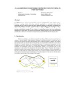
Figure 5
Label-switched paths established from edge
to edge.
mapped onto the label-switched path, need
only be known by the ingress label-edge
router. The use of the resource reservation
protocol also implies that RSVP mecha-
nisms may be used for allocating resources
and QoS properties to the explicitly routed
label-switched paths.
RSVP in MPLS networks
An integrated-services framework has been
specified by the Internet Engineering Task
Force (IETF) for sessions whose quality-of-
service requirements exceed best-effort ser-
vice. The framework includes the RSVP pro-
tocol for reserving resources for session flows
and a set of services. The services that have
been specified to date are controlled load and
guaranteed quality of service.
Two basic message types have been de-
fined for the resource-reservation protocol.
A PATH message is sent from the source to
announce a flow. It conveys a traffic de-
scriptor (in the form of token bucket para-
meters—much the same as for ATM), and
is routed through the nodes of the IP net-
work to the destination. To reserve resources
for the flow (for example, bandwidth on
links), the recipient returns an RESV mes-
sage along the same path.
The RSVP messages are processed by the
MPLS nodes—label-edge routers and label-
switch routers—along the path. As a result
of the RESV messages, a label-switched path
and a corresponding ATM connection are
set up through the MPLS domain. As the
RESV message is processed, the label-edge
router and LSR-CC
• transform the RSVP traffic descriptors
into the corresponding ATM parameters
(CBR, VBR and ABR provide appropri-
ate service for these connections);
• allocate a label before the message is prop-
agated upstream to the source;
• connect the label-switched path ATM
connection through the node.
The label is propagated to the upstream
node in a label object contained in the RESV
message.
Although the RSVP specification has
been available for some time, it is not yet
widely deployed. The present generation of
routers, which are optimized for best-effort
traffic forwarding, are not suited for han-
dling large amounts of flows in a
connection-oriented fashion. Multiprotocol
label-switching ATM, however, offers a
highly scaleable RSVP solution.
Real-time multicast sessions are expected
to become one of the first applications to use
the resource reservation protocol. In multi-
protocol label-switching ATM networks,
the ATM point-to-multipoint connection
will be used in much the same way as for
multicast functions. The branching nodes
may be situated at the label-edge router as
well as at label-switch router nodes. The
RSVP framework also comprises sessions
with multiple senders; that is, multipoint-
to-multipoint sessions. Until support is pro-
vided for multipoint-to-point connections
in ATM, merge points will have to be lo-
cated outside the multiprotocol label-
switching ATM domains or in label-edge
router nodes.
36
Ericsson Review No. 1, 1998
Box B
MPLS standardization work
The MPLS working group within the IETF is
standardizing the basic technology for
using the label swapping forwarding para-
digm in conjunction with network layer rout-
ing and for implementing that technology
over various link-level technologies, which
may include packet-over-Sonet, frame
relay, ATM, Ethernet (in all its forms), and
token ring.
Their work includes procedures and proto-
cols for the distribution of labels between
routers, encapsulations, multicast consid-
erations, use of labels for supporting high-
layer resource reservation and QoS mech-
anisms, and the definition of host behavior.
Their objectives are:
• to specify standard protocol(s) for the
maintenance and distribution of label-
binding information, to support unicast
destination-based routing with forwarding
based on label-swapping;
• to specify standard protocol(s) for the
maintenance and distribution of label-
binding information to support multicast
routing with forwarding based on label-
swapping;
• to specify standard protocol(s) for the
maintenance and distribution of label-
binding information, to support the hier-
archy of routing knowledge (for example,
the complete segregation of intra- and
inter-domain routing) with forwarding
based on label-swapping;
• to specify standard protocol(s) for the
maintenance and distribution of label-
binding information, to support explicit
paths that differ from the path con-
structed by destination-based forwarding
with forwarding based on label-swapping;
• to specify standard procedures of carry-
ing label information over various link-
level technologies;
• to specify a standard way of using the
ATM user plane,
a) allowing operation/coexistence with a
standard (ATM Forum, ITU, etc.) ATM
control plane and/or standard ATM
hardware;
b) specifying a label-swapping control
plane;
c) taking advantage of possible modifi-
cations/improvement in ATM hard-
ware; for example, the ability to merge
virtual channels;
• to discuss support for QoS (for example,
through the RSVP);
• to define standard protocol(s), to allow
direct host participation (for example, by
a server).
Ericsson Review No. 1, 1998
37
Differentiated services
Given the problems of scaleability current-
ly found in the integrated-services frame-
work, a new set of services is being studied
by the IETF. The objective is to provide ser-
vice and the corresponding tariff differenti-
ation with which to fulfill the immediate
needs of business and residential users. The
work has just begun, but the service model
will most likely be based on static service
profiles of users, defining the capabilities of
the subscriptions (such as bandwidth),
network-edge functions that police the pro-
file, and tag packets as they enter the net-
work. The tagging of packets, which classi-
fies traffic according to delay requirements
and by value or importance, is used by core
routers for scheduling, handling congestion,
and so forth.
MPLS flows with different delay require-
ments may be mapped onto label-switched
paths and the corresponding LSP-ATM con-
nections with different classes of service and
priority. Tags that denote value and impor-
tance may be translated into cell-loss prior-
ity tags.
Multicast functions
To support distributive and multiparty ser-
vices, IP networks provide multicast capa-
bilities. A separate address suite has been
dedicated to multicast services. A main ob-
jective of these service is to save network re-
sources by creating copies of each packet as
close to the receivers as possible. Therefore,
multicast trees are built up for each service
as recipients announce themselves. During
configuration, the trees may be rooted at the
sender or at defined root node for the mul-
ticast group. A separate set of routing pro-
tocols, optimized for different network and
multicast situations, has been defined for
this purpose. The nodes—label-edge
routers and label-switch routers (LSR-
CC)—of an MPLS network that is to be used
as part of multicast trees must implement
the multicast routing protocols used in the
network.
As the topology of a multicast tree is cre-
ated and changes, a point-to-multipoint
label-switched path is built up in a similar
manner as for a unicast label-switched path.
In multiprotocol label-switching ATM, a
corresponding ATM point-to-multipoint
connection is also created using the same
principles as for unicast label-switched
paths and using the ATM point-to-
multipoint capability found in the branch-
ing label-switch router nodes.
Ships in the night
Multiprotocol label switching can also be
deployed in an ATM network that is used
for other ATM services that use user-
network-interface (UNI) or private-
network-network-interface (PNNI) signal-
ing for connection control. In the MPLS lit-
erature, this kind of configuration is named
ships in the night. Resources must be dedi-
cated to the MPLS application through con-
figuration in each node. The allocation of
resources is accomplished with different de-
grees of granularity. Nodes can be dedicat-
ed to function as label-switch routers. In
mixed nodes, interfaces or even partitions of
interfaces (bandwidth and VCI/VPI ranges)
may be allocated to the MPLS service.
Implementation
In the AXD 301, multiprotocol label
switching is implemented as a software sub-
system, allowing nodes to run as either a
pure MPLS node, or as a ships-in-the-night
node.
The MPLS subsystem, which is divided
into several blocks (Figure 7), has two im-
portant interfaces to the underlying system:
one interface is used for controlling the
switch via the basic ATM connection-
control services module
1
; the other interface
uses AAL5 for traffic to and from MPLS
peers.
MPLS
Basic AXD 301 system modules
Fig 6
Multiprotocol label switching and other appli-
cations on top of the basic AXD 301.
TCP/IP
Routing
protocol
L3F
FIB
LDP
AAL5
REH
Basic ATM
connection control
services module
LIM
Fig 7
System structure.
Connection control API
The connection-control application pro-
gram interface (API) of the AXD 301 allows
the MPLS subsystem to control the switch:
it allows multiprotocol label switching to
establish and release point-to-point connec-
tions across the switch, add and delete leaves
on point-to-multipoint connections, speci-
fy quality-of-service requirements for the
connections, and receive port status infor-
mation.
Several switch vendors support the gen-
eral switch management protocol (GSMP).
2
The connection-control API of the
AXD 301 contains primitives similar to
those supported by the general switch-
management protocol, which makes it pos-
sible to port the MPLS application to other
switches—provided they support GSMP.
However, the AXD 301 implementation
deviates somewhat from the GSMP, which
presupposes that the controller and the
ATM switch are two separate boxes con-
nected via an ATM link. Therefore, in the
AXD 301, the adjacency protocol for syn-
chronizing the controller and switch has
been cut out.
The GSMP is a single protocol for control
plane and management plane operations.
Since the management of the MPLS subsys-
tem adheres to the management of the
AXD 301, the GSMP primitives that relate
to operation and maintenance are not im-
plemented in the API.
Moreover, the GSMP does not differenti-
ate between point-to-point and point-to-
multipoint connections, although in most
existing ATM switches, including the
AXD 301, resource requirements differ for
the two types of connection. Therefore, to
fully exploit the switch, the API offers a
primitive for establishing pure point-to-
point connections.
The GSMP approach to quality of service
assigns a level of priority to each connection.
For virtual-channel connections that share
the same output port, it is assumed that an
ATM cell on a high-priority connection is
more likely to exit the switch before an ATM
cell on a low-priority connection, provided
they are in the switch at the same time.
Clearly, this approach is inadequate if
throughput and delay-related guarantees
must be given to a label-switched path;
therefore, the API augments the QoS capa-
bilities of the GSMP.
Initially, the AXD 301-based implemen-
tation of the interface will map all best-
effort traffic to the UBR traffic category.
Since control traffic, such as routing-
protocol traffic and label-distribution-
protocol traffic, must get through—espe-
cially when the network is congested—it
will be possible to map control traffic to
high-priority traffic classes; for example, to
the CBR traffic class.
The resource handler (REH), which keeps
track of available bandwidth and VPI and
VCI values for the switch interfaces, offers
primitives for setting up and releasing con-
nections through the switch. Since the re-
source handler serves other subsystems be-
sides MPLS, it can be used as a coordinator
for running ships-in-the-night; that is, co-
existing applications. In that case, a small
amount of available capacity is allocated to
each UBR connection, thereby ensuring
that the other subsystems do not use up all
available bandwidth.
Label distribution and
LSP establishment
The label-distribution protocol is used for
distributing label bindings. Drafts pub-
lished to date indicate that the user data-
gram protocol (UDP) is used for carrying a
neighbor discovery protocol while the trans-
mission control protocol (TCP) is used for
distributing the label bindings.
The routing protocol that runs on the
MPLS node may vary depending on how the
node is deployed. Initially, OSPF is used for
intra-domain routing.
Routing computations are often quite ex-
pensive. OSPF uses the shortest-path-first
(SPF) algorithm (also known as Dijkstra's
algorithm) to compute the best route for
each destination. The algorithm puts a com-
putational burden on the system, which may
potentially interfere with the establishment
of the label-switched path.
The FIB block generates events that cor-
38
Ericsson Review No. 1, 1998
Box C
IP over ATM
Many solutions have been proposed for run-
ning IP over ATM:
• Classical IP, defined by the IETF, is a way of
building logical LANs on top of ATM.
• LAN emulation (LANE), defined by the ATM
Forum, is a way for an ATM network to emu-
late a logical Ethernet or a token ring seg-
ment.
• Next-hop resolution protocol (NHRP),
defined by the IETF, is a way of intercon-
necting logical LANs over ATM.
• Multicast address resolution server
(MARS), defined by the IETF, supports mul-
ticast over ATM.
• Multiprotocol over ATM (MPOA), defined by
the ATM Forum, integrates LANE and NHRP
into a unified whole for use within private
networks.
Several attempts have been made at pro-
moting proprietary solutions.
Ericsson Review No. 1, 1998
39
respond to changes in topology. When the
routing protocol inserts a new entry, deletes
an entry, or updates an existing entry in the
forwarding information base, the FIB block
generates a corresponding event. The event
is received by the label-distribution proto-
col, which then acts accordingly; that is,
• if a new entry has been added, it estab-
lishes a new label-switched path;
• if an entry has been deleted, it releases the
corresponding label-switched path;
• if an entry has been updated, indicating a
new route to the destination, it re-
establishes the label-switched path.
The LIM block manages the label informa-
tion base, keeping track of the relationship
between a label binding at an incoming in-
terface and a label binding at the outgoing
interface for each forwarding equivalence
class. This relationship corresponds to a con-
nection through the switch—from the
VPI/VCI of the binding at the incoming in-
terface to the VPI/VCI of the binding at the
outgoing interface. The LIM block keeps
these connections current with existing
label bindings.
Layer-3 forwarding
The L3F block is responsible for forwarding
unlabeled traffic. In normal operation, all
traffic in the MPLS network runs over es-
tablished label-switched paths. However,
there are situations where unlabeled traffic
may enter the network:
• When the edge router has not yet estab-
lished a label-switched path for traffic and
the router permits unlabeled traffic to pass.
• An interface fails, making it impossible
for labeled traffic to exit the node through
the interface; therefore, to avoid black-
holing packets, they are handled by the
L3F block.
• A node in the core network has aggregat-
ed several prefixes that exit the network
through different edge routers—in which
case the L3F block must look up the
layer-3 address to find the correct outgo-
ing interface at the node.
All unlabeled traffic runs over a default
VPI/VCI. Thus, the task of the L3F block is
to look up the layer-3 address of incoming
packets in the routing table in order to de-
termine which outgoing interface the pack-
et should use for exiting the node. By ex-
tending the look-up function to return both
the outgoing interface and the outgoing
VPI/VCI, the L3F block effectively performs
the role of an edge router.
The layer-3 forwarding function is con-
nected to the TCP/IP block for traffic that
terminates in the node itself and for unla-
beled traffic that originates in the node.
Availability
The AXD 301 gives the MPLS subsystem
traditional telecom characteristics, such as
robustness and high availability.
The use of the Erlang programming lan-
guage and the open telecom platform (OTP)
lay the foundation for a system with high-
quality software.
The dual central processors and control
system of the AXD 301 distribute func-
tionality so that the capacity-demanding
routing-protocol computations do not in-
terfere with the establishment of label-
switched paths; that is, the routing-
protocol block and the LDP block are allo-
cated to different central processors.
The forwarding information base is repli-
cated on each central processor. Thus, if one
processor fails, the MPLS blocks running on
that processor move to the other processor
without having to build up the forwarding
information base from scratch (which would
be comparable to restarting the MPLS node).
When the failed processor is taken back into
service, the routing-computation function
moves to it, leaving the label-switched-path
handling undisturbed.
Conclusion
Offering support of emerging new services
with requirements for throughput and the
bounds of delay, and by offering extended
traffic-engineering possibilities, multipro-
tocol label switching addresses many of the
problems currently inherent in the Internet.
By using ATM as a link technology, the
fundamental label-swapping paradigm is
supported by hardware. The forwarding
functions in MPLS networks can then lever-
age the price-per-performance properties,
throughput, and quality-of-service features
of ATM switching.
Multiprotocol label switching is primar-
ily a solution for IP-over-ATM backbones.
Its implementation on the AXD 301 gives
MPLS nodes traditional telecom character-
istics, such as robustness and high avail-
ability.
References
1 Blau, S. and Rooth, J.: AXD 301—A
new generation ATM switching system.
Ericsson Review 75(1998):1,
pp. 10-17
2 Newman et al.: Ipsilon’s General
Switch Management Protocol Specifica-
tion, RFC 1987, August 1996.