Fine tuning air conditioning and refrigeration systems
Bạn đang xem bản rút gọn của tài liệu. Xem và tải ngay bản đầy đủ của tài liệu tại đây (26.85 MB, 128 trang )
air co~ditio~ing and refrigeratio~ systems/
in~ E~iciency.
2.
aintenance
and
repair.
3,
ting machinery” air.
4.
Air
condition in^"
.
Refrigera~o~ and refrigera~g machinery
Fine t~ning air ~onditioning and re~ige~ation s~ste~s~ill~
C.
~~gle~.
002
by The F~irmo~t Press. All rights reserved.
No
part of this ~ublication may be
itted in my form or by any means, ~~ectronic or ~~cha~ical, includin
or
any i~fo~ation storage and retrieval system, without
erm mission
in wri~g from the publis~er.
Published by The Faimont Press, Inc.
700
Indian Trail
Lilburn,
GA
30047
Printed in the United States of America
While every effort
is
made to provide dependable information/ the publisher, authors, and editors cannot be held
responsible for any errors or omissions.
Distributed by Prentice Hall PTR
Prentice-Hall, Inc.
A
Simon
&
Schuster Company
Upper Saddle River, NJ
07458
Prentice-Hall Inte~ational
(UK)
Limited, London
Prentice-Hall of Australia
Pty.
Limited, Sydney
Prentice-Hall Canada Inc., Toronto
Prentice-Hall Hispanoamericana,
S.A.,
Mexico
Prentice-Hall of India Private Limited, New Delhi
Prentice-Hall of Japan, Inc., Tokyo
Simon
&
Schuster Asia Pte. Ltd., Singapore
Editora Prentice-Hall do Brasil, Ltda., Rio de Janeiro
m
t-r
R
m
CP
m
m
R
R
t-r
/-4
0.2
n
W
W
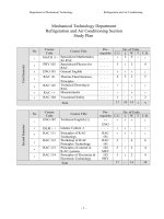
C~p~er
10
§ti~ating Annual eating Re~uirements
109
A~~e~~ix A
ir ~on~itioning Formulas (Non-P§ychro~~tr~c)
11
Appe~~ix
B
rksheets
11
This manual was written to provide the service tec~ician with the proce-
dures necessary to bring heating, air condition~g, and ref~geration sys-
tems, including heat pumps, to full operating e~iciency. This manual was
not intended to present "standard" service procedu~es but rather to pro-
vide advanced info~ation and procedures that, when followed, cause the
e~uipment to operate as it was designed
by
the manufac~rer.
en used properly, the procedures presented in this manual will ensure
ment operates more economically and to
full
capacity
an
has a longer life with
a
minimum amount of repairs.
It would have been im
manuf~cturers and friends who are conc
with this indus-
con~ibutions over the past
35
years have
a manual
of
this
le. They have been
m
e this text feasib
those
companies and individuals who value this
dust^
as much as I
do.
ere are many reasons for fine ~ing heating, air condi~oning/ and refrig-
eration equipment/ such as energy conservation, cost effectiveness, less
need for new power plants, improved perfo~ance, and equipment longev-
ity. It is true it takes more time to fine tune equipment
so
that it operates
at peak efficiency/ and this comes at a greater cost to the customer.
How-
enefits are properly explained, most are willing to pay the
service fee, which is usually saved many times over through the more ef-
onomical operation of the e~uipment. Also, the technician
ility and desire to fine tune equipment can charge extra for
ill always be in demand by the public.
cause of the constantly dec
'
of oil, every possible step must
made to conserve its use. ating, air conditioning/ and re-
ration e ui ment is a very good place to start, because air conditioning
est users of electricity in residential and many commercial
heating, air conditioning/ and refrigeration units are oper-
ciency this percentage of power consumption is reduced
much as
25%.
Several tests have proven that nine out of
eration units are operating at a re-
duced efficiency that is between
10%
and
40%
of their rating.
ition~g, and refrigeration equipment is operating
and the cost of operation is reduced. Thus, the
customer is saving money. When the technician fine tunes the equipment
so
it operates more economically, the customer is more satisfied and is much
more pleased with the service provided. The service technician can usually
charge more for providing this fine tuning service, because the customer is
more willing to pay for d, thorough service that ensures the e~uipment
is operating as des cause of this, both ties are satisfied and the
customer is more a mend the technic to others who may want
this type of service.
When heating, air conditioning, and refrigeration equipment is working at
peak efficiency, power generating plants cm be operated at less than
h11
capacity. The power company not only saves on operatin expenses, but the
need to build new power plants to furnish power to inefficiently operating
equipment is no longer a considera~on.
Thus,
the need for costly power
plant construction and operation is eliminated.
Properly tuned heating, air conditioning, and refrigeration equipment per-
forms better than equipment that is not properly adjusted. The customer
will be more satisfied with the operation of fine tuned equipment.
In
addi-
tion, the unit will keep the building more comfortable, the process refrigera-
tion and heating equipment will satisfy the demands much more easily, and
there will be less service and maintenance required.
Fine tuned equipment has the proper amount of refrigerant and oil flowing
through the system to maintain properly lubricated components at their de-
sired operating temperatures. Properly lubricated equipment operating at
the desired tem~erature usually lasts much longer than equipment that
does not have these characteristics.
Thus,
the customer is saved the cost of
having to replace the equipment, and major repairs are either eliminated or
postponed to a much later date.
A
check of the operating refrigerant pressures and temperatures, along with
determining the airflow through the unit and the temperature rise or drop
of the air, is usually all that is needed to determine the efficiency of the unit,
or more of these operating factors usually
unit. Of course, the ductwork,, insulation,
and the condition of th re will determine, to a great extent, whether
or not the system will the desired conditions inside the building.
All of these factors
must
be considered when fine tuning equipment to
ensure
more
complete customer satisfaction. member, the best equipment
will not perfom if it is insta llation is also a part of fine
ing
a unit. The unit ma peak efficiency,, but if the con-
oned air cannot reach t
S
not properly distributed, the
result will still be
or
ope ratio^.
Give the ins~a~lation a thorough inspec-
tion, and inform customer of anything that can,, or must, be done to
obtain optimum efficiency an
This Page Intentionally Left Blank
of
the amount
of
heat input to
vered by the hrnace.
in
both residential and commercial applica-
ree-phase element designs.
it
is
important that electric
prevent drafty conditions.
units is probably the
units available. The
e proper test hstr
ny rate, accurate test
inst~ments must be used for testing the efficiency of electric heating units.
The exact procedures for inst~ment use are found in the manufacturer’s
operating il~structions. The inst~ments must be properly cared for an
their accuracy maintained for optimum performmce.
This chapter will discuss the specific procedures used to fine tune electric
heating units, not specific inst~ments. The following is a list of the basic
test inst~ments required for testing and adjusting the efficiency of electric
heating units:
1.
Dry
bulb thermometer
3.
Voltmeter (a wat~eter may be used in lace of the ammeter and
.
eter er
vol~eter)
A
dry bulb (db) thermometer is used for checkin
2-1.
~eter~~ng the temperature rise
of
the ai
heating unit is a very important step
in
the fine ~ng process. The dry
bulb tempera~re is a measure of the heat absorbed from the heating ele-
ments by the air. The air temperature is measured in
two
locations: the
return air stream and the discharge air stream, Figure
2-2.
the tempera~re readings after the mixing of
my
air and within
6
ft of the
air handling unit. The thermometers must be placed where the radiant heat
from the elements cannot be measured by the thermometer. Radiant heat
can cause a faulty tempera~re reading and
an
incorrect test.
Two different thermometers that have been tested
an
found to produce
exactly the same read~gs under the same set of cir~mstances should be
used. If two thermometers that read exactly the same tempera~res are not
ry
bulb
t~ermom~ters (Cou~esy, wyer Instruments, Inc.)
Do
not
rneasure
6
ft
rna%i~u~
air
are
~i%ed)
ir
in
a
I
circulatin~ air te~p~rature
available, then use one thermometer to measure both temperatures.
An
~ometer that has se arate, properly adjusted leads also pro-
ired results. The best temperature rise
of
an electric
heating unit is about
40”
to 50°F.
S
the blower to run longer,
the air more evenly thro~ghout the building.
e ammeter is used to determine the amount
of
electrical current used by
-on type ammeter is the most popular, because the
be measured without separating the wire. These inst~ments
ccurate when the wire being measured is in the center of the
The voltmeter is used to meas~re the voltage in a wire, Figure
2-3.
The
-type meter is the most accurate when the indicator is in the center
of the scale. The
1
be checked regularly to ensure they are in
n the insulation becomes worn or cracked,
firm, solid fit between the meter and the
fitting lead can give an improper voltage
Figure
2-3.
~igital multimeters (Courtesy,
AM
Sperry Instruments,
Inc.)
e wattmeter is used to measure the voltage to the unit and the total
wattage used by the unit. ese inst~ments are usually more accurate than
voltmeter and ammeter to determine the total wattage used by the unit.
wever, wat~ete~s are more expensive.
The
analog-type wa~eter is the
most accurate when the indicator is reading at the mid-scale point.
ending on the size and type of installation/ bo single- and three-phase
heating elements are used. When dete~ining lowatt input, be sure to
measure the total voltage and amperage to the unit, including the fan
motor, because it also adds heat to the air.
en
more than one heatin
element is used, check the fan motor separately to prevent adding the
motor amperage to each element.
The
meas~rements should be taken at a
close disco~ect switch or where the electrici~ enters the unit, not at a
distant point.
To
dete~ine the capaci~
of
an electric heating unit, first dete~ine the
tu
input to the unit by perfo~ing the following steps:
1.
3,
4.
5.
easure the voltage and amperage to the fan motor and each heatin
element.
Add together the amperage draw of each heating element and the fan
motor.
h et ermine
the unit wattage by multiplying the voltage by the amper-
age. Use the following formula:
where:
Determine the unit
Btu
output by multiplying the wattage by 3.413.
Use the followin
tu
=
etermine the blower
ch
by dividing the
tu
by 1.08
x
AT.
Use the
appropriate formula:
cfm
=
cfm
=
cfrn
=
Make certain that all the return an rilles are open and unob-
structed. If an air conditioning unit
is
included, make certain that the coils
and filters are clean.
6.
Determine the
AT
by using the following steps:
a. Allow the unit
to
m
continuously for about ten minutes.
b.
To
avoid the~ometer error,
U
c. Measure the temperatu~s at a point where the thermometer can-
sure the return and supply air te
not "see" the heat source (see
F
cannot be measured when radia
eter.
d.
The
air temperature measur~ments must be taken within
6
ft of
the air handling
unit.
The return air temperature can be taken at
the return air grille if it is located close to the unit, as in Fi
2.
The air temperature taken at the supply air grille is not usually
accurate enough for this purpose.
e. Men more than one discharge or return air uct is connected to
the plenum, use the average rature (AT). For example,
1
=
115"F,
Duct
2
=
llO°F/
Use the follow~g
formula:
AT
=
Number
of
ducts
7"-
=
112"
f.
Be sure to ta the temperature measurements after any source
of
7.
Check the manufac~rer's speci~cations for the par~cular unit to see
mixed air, such as a fresh air intake.
if these conditions meet the design criteria.
en the cfm is too high, slow the blower. n the discharge cfm is too
low, speed up the blower.
en
a direct drive motor
is
used, the cfrn can
be changed by moving the electric wire to a lower or higher speed te~inal
en a direct drive motor ca~~t be wire to deliver the correct cfm/ use
e the air inlet to the blower.
Be
sure to make
otor to prevent overheatin
cfmf and secure
f
sheet metal cut
lower is
used,
the cfm can be c
r shaft.
To
incre~se the
the pulley halves.
te~~erat~re ~i~~s
re~~r~
air te~~erat~re.
city b
t
is not heat
ure
the cfm from each one, and total them.
If
the
insulation.
t
en the duct system meets this criteria, the only other alternative
is
to
more capacity. This cm be done by either adding more heat strips
or
installing some with higher capacity ratings. Table 2-1 lists the tempera~re
rise, the
kW
rating of the furnace, and the corres~onding cfm. This informa-
tion can be used to reduce the time required to get a very close estimate of
how
efficient the unit is operating.
700
53
-
59 79
-
-
-
-
32 7
63
- - -
26
39
53
- - -
- - - -
20 30
40 49
59
69
79
18 26
35 44
53 61 70
16 24
32 40
47 55 63
14
22
29
36
43
50
57
-
16 21
26 32
37 42
20
25 30 35 40
-
-
18
22
26 30 35
S
about insu~icient heat from an electric heating unit, th
heating elements are delivering the amount of heat they
W
at one or more of the heating elements is not operating properly. This
is
is easily pe~ormed.
er, voltmeter, accurate thermometer, and tool kit. An accurate wa~meter may
rocedures:
electricity to any other equipment that
is
used in conjunction with the electric
h
et the thermo~tat to de~and heat. Allow the heater to operate for approximately
10
minutes
so
the tempe
tures will st~bilize.
easure the voltage an amperage of each heating element and record:
Volts Amps
otor:
1.
eater:
1.
3.
Sum:
total wa~age of the heat strips and record. Use the followin
=Vxl
_.
_.
5.
ete ermine
the
U
output of the heat strips and record. Use the following formula:
tu
=
etermine the cfm of the blower and record. Use the following instructions:
*
Use the same thermometer, or
two
that measure exactly the some, to measure the return and supply air
temperatures.
*
Do not measure the temperature in an area where the thermometer can sense the radiant heat from the
heat strips (see Figure
2-2).
True air temperature cannot be measured
if
the thermometer senses radiant
heat.
5
Take the temperature measurements within
6
ft
of th n at the return and
supply grilles that are at too great a distance from the unit are not usually accurate enough.
*
Use the average temperature when more than one duct is connected to the supply air plenum.
*
Be sure the air temperature has stabilized before taking the temperature measurements.
5
Take the temperature measurements downstream from any source
of
mixed air. Use the following formula:
cfrn
=
Btu
1
.Q8
x
AT
cfm
=
7.
Is
this what the manufacturer rates the e~uipment?
ultiple tear-out copies
of
this worksheet
The purpose of adjustin the e~ciency of any piece
of
equipment is to
deliver the most energy ossible to the conditioned space or process.
The
efficiency of a gas-fired furnace or boiler is the difference between the input
and the actual amount of heat produced by the unit. The efficiency adjust-
ment must provi ain without producing undesirable condi-
tions. In mathematical terns, efficiency is explained as:
Total energy
The components must be clean and in good working condition, and clean
air filters must be installed.
There are several close1 in the adjus~~nt pr~ess.
When an adjus~~nt i ctors, the other factors a
also affected. There is r or r to follow when making efficiency
ral categories of these factors
are as follows:
e comb~~on process
rtant part in overall unit
r are mixed in the proper
set this gas-air
relations hi^,
th
tion. Therefore, the burner
m
re are several factors that aff
unit’s e~iciency, such as the
r
m~x~g
of
the
gas
and
air.
e proper test ~st~ments are
is chapter will discuss th
heating units, not sp~cific i list of basic test
~s~rne~ts re the efficiency of
6.
7.
e
one
of the
first
steps
t, because
if
the heat is