FATIGUE BEHAVIOUR OF FIBRE REINFORCED BITUMINOUS MIXTURES FROM INDIRECT TENSILE FATIGUE TEST
Bạn đang xem bản rút gọn của tài liệu. Xem và tải ngay bản đầy đủ của tài liệu tại đây (253.84 KB, 13 trang )
FATIGUE BEHAVIOUR OF FIBRE REINFORCED BITUMINOUS
MIXTURES FROM INDIRECT TENSILE FATIGUE TEST
Ibrahim Kamaruddin
Universiti Teknologi Petronas, Malaysia
ABSTRACT
Fatigue behaviour of bituminous mixtures is characterised from the relationship
between stress or strain level and the number of load repetitions to failure. This paper
presents the results of a laboratory investigation to assess the influence of polymer
fibres on the fatigue characteristics of Hot-Rolled Asphalt (HRA) mixtures. Polyester
and polypropylene are the two types of fibres added to the bituminous mixtures. The
fibrous HRA are subjected to two types of laboratory fatigue tests; indirect tensile and
the beam flexural test. A constant stress test regime was adopted with all the mixtures
tested under identical conditions of applied stress, frequency of loading, temperature
and support conditions. Fatigue equations obtained from both tests are presented. It
appears that the incorporation of synthetic fibres in bituminous mixtures improves the
fatigue performance of the mix despite the higher void content of the specimens
incorporating the fibres. This takes place despite the fact that fatigue performance
generally deteriorates when the void content is increased. The higher strain capacity
of the fibre-modified mixtures is attributed to the higher bitumen content and the
thicker bitumen film coating the aggregates. Comparison of the fatigue relationship
obtained from the Indirect Tensile Fatigue test and that of the Beam Flexural test
revealed that the fatigue lines for both tests do result in approximately a single line
defining the fatigue behaviour of the mixtures tested.
Keywords: Bitumen, Bituminous Mixtures, Fatigue, Hot-Rolled Asphalt,
Polypropylene and Polyester Fibres
1.0 INTRODUCTION
Excessive permanent deformation and cracking are generally accepted as the main
forms of distress in bituminous road pavements. While permanent deformation
occurs predominantly at elevated temperatures, thermal cracking is normally a low-
temperature phenomenon.
In addition to temperature, cracking can also be brought about by traffic loading. Load
associated fatigue cracking is the phenomenon of fracture as a result of repeated or
fluctuating stresses brought about by the traffic loads. Traffic loads can cause a
pavement structure to flex and the maximum tensile strain will occur at the base of the
bituminous layer.
Cracking occurs when the thermally induced tensile stresses, together with stresses
caused by traffic, exceeds the tensile strength of the material. If the structure is
inadequate for the imposed loading conditions, the tensile strength of the material will
be exceeded and cracks are likely to initiate, which will be manifested as cracks on
the surface of the pavement. As a result, it is generally assumed that there is a
significant reduction in the load distribution capacity within the pavement.
This paper describes and presents the results of a laboratory investigation to assess the
influence of polymer fibres on the fatigue characteristics of Hot-Rolled Asphalt
(HRA) mixtures.
2.0 MATERIALS USED IN THE INVESTIGATION
2.0.1 Mineral Aggregates, Filler and Bitumen
Limestone aggregates and Ordinary Portland Cement (OPC) filler and a binder of
nominal penetration 50 were used. Some relevant properties of these materials are
shown in Table 1.
Table 1: Properties of the Mineral Aggregates, Filler and Bitumen Used in the Study
MATERIAL
PERCENTAGE
BY WEIGHT (%)
RELATIVE
DENSITY
ABSORPTION
(%)
BS
SPECIFICATION
Coarse
Aggregate
35 2.75 0.47
BS 594: Part
1:1992 Table 3,
Type F Wearing
Coarse Designation
30/14
Fine Aggregate
(Sand)
55 2.65 1.37
Filler OPC) 10 3.15
Bitumen
Penetration (dmm)
Softening Point
(
o
C)
Penetration Index
(PI)
BS 4699:1985
52 48.5 -0.37
2.0.2 Synthetic Fibres
Two types of synthetic polypropylene and polyester fibres were used in this study.
The fibres were used as a partial replacement of the filler, on an equal volume basis,
at two different concentrations of 0.5% and 1 % filler/bitumen ratio by weight of mix.
The fibres; in chopped form; were the by-products of the textile industry and thus
their potential use was desirable on environmental grounds. Some characteristics of
the fibres used are shown in Table 2. In order to maintain thermal stability when
using the polypropylene fibres, it was decided that the mixing temperature during the
preparation of the HRA mixtures should not exceed 140°C and compaction be done at
130°C.
Table 2: Characteristics of Fibres Used
FIBRE
TYPE
SPECIFIC
GRAVITY
DENIER
LENGTH
(mm)
AVERAGE
DIAMETER
(µ
µµ
µm)
DEGRADATION
TEMPERATURE
(
o
C)
Polypropylene
(PP)
0.91 6 6 22*
≈ 160 - 170
Polyester
POL)
1.41 3 6 17*
≈ 250 - 260
*Values obtained from 20 readings using a light microscope at 400x magnification.
3.0 FATIGUE RELATIONSHIP
Fatigue tests can be carried out in two principal methods, namely the constant stress
tests where the stress level is kept constant throughout the test and the constant strain
tests where the magnitude of the peak cyclic strain is kept constant throughout the
test. Before the fatigue performance of a bituminous material can be assessed, the
failure of the specimen tested must be consistently defined.
Defining the failure criterion in the constant stress mode is relatively easy as the
specimens undergo a relatively short crack propagation period. Hence, the failure
point is taken as when the specimen has completely failed. However, in the constant
strain mode of loading, the failure point is not very well defined, due to the large
amount of crack propagation included in the test. An arbitrary point of failure must
thus be assumed which is normally defined as the point when the specimen has
reached a reduction in its initial stiffness of 50% or in practical terms is the point
when the stress applied has been halved to achieve a constant strain.
A linear relationship exists between the log of stress
σ
, or strain
ε
, and the log of the
number of load repetitions, N
f
to failure. The failure criteria can therefore be
expressed as:
Log. stress against log. load applications.
Log. strain against log. load applications.
This can be written in the form:
Log (
σ
or
ε
) = a + b log N
f
For the strain controlled tests, the results are normally presented in the form
N
f
=A
b
ε
1
while in the stress controlled tests, the results are presented in the form
N
f
=A
d
σ
1
where N
f
= Number of load applications to failure
σ
,
ε
= Tensile strain or stress repeatedly applied load
A,b,C,d = Material coefficients
4.0 INDIRECT TENSILE FATIGUE TEST (ITFT)
The indirect tensile fatigue test was employed in order to characterize the fatigue
behaviour of the HRA specimens in the laboratory. The test was conducted in the
Universal Material Testing Apparatus (UMATTA) with the appropriate force, rise
time and pulse repetition period being selected. For each loading pulse, the
accumulated displacements were continuously being calculated and displayed. Read
and Brown (1994) were of the opinion that the Indirect Tensile Fatigue Test is able to
characterize the fatigue life of a bituminous mixture by testing a small number of
specimens (less than 10) at high temperatures (in excess of 25
o
C) and at high stress
levels (greater than 450 kPa). This means that the fatigue testing time needed to
produce an adequate fatigue relationship for a bituminous material is significantly
shorter than other traditional laboratory fatigue testing methods.
In the indirect tensile fatigue test, a repeated line of loading (generally controlled
stress) is applied along the vertical diameter of a cylindrical specimen. The vertical
load produces both a vertical compressive stress and a horizontal tensile stress on the
diameters of the tested specimen. The magnitude of the stresses changes along the
diameter of the specimen with a maximum occurring at the center. Assuming that the
specimen is homogeneous, isotropic, behaves in a linear elastic manner and subjected
to a plane stress condition; the stress conditions in the specimen can be calculated for
a known Poisson's ratio ν when the force, P applied is a line load.
σ
xmax
=
dt
P
π
2
(Equation 1.0)
σ
ymax
=
dt
P
π
6
(Equation 1.1)
where:
σ
xmax
= Maximum horizontal tensile stress at the center of the specimen
σ
ymax
=
Maximum vertical compressive stress at the center of the specimen
d = Specimen diameter
t = Specimen thickness
By simple linear elastic stress analysis (Hooke's Law):
ε
xmax =
m
x
S
max
σ
=
m
y
S
v
max
σ
(Equation 1.2)
where:
ε
xmax
= Maximum initial horizontal tensile strain at the center of the specimen
v
= Poisson's ratio
S
m
= Stiffness modulus of the specimen
By substitution;
ε
xmax =
m
x
S
max
σ
( )
v3 1+
(Equation 1.3)
Equation (1.3) is used for the calculation of the maximum tensile strain (
ε
xmax
) at the
centre of the specimen that is dependent on the stiffness modulus of the material.
This parameter was obtained from the Indirect Tensile Stiffness Modulus test at the
same stress level and test temperature as the ITFT.
The specimen geometry selected for all the ITFT was 100 mm in diameter by 40 mm
thick. The specimen was first conditioned at the test temperature of 20+0.5
o
C for
between 2-4 hours before testing commenced. A cyclic load pulse was applied to the
specimen with a time to the peak of the load pulse being 120 ms. A loading rate of
40+1 pulse/minute at the test stress level were employed and the permanent vertical
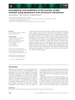
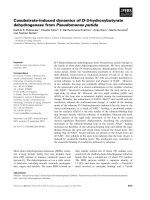
deformation measured by a linear variable differential transducer (LVDT). Figure 1
relates the strain-number of cycles to failure that was typical of the output obtained on
the UMATTA during the test which shows an initial period of comparatively large
displacement followed by a part that represents a constant rate of strain amplitude.
Finally the curve started to concave indicating the point of failure.
Figure 1 Typical Indirect Tensile Fatigue Test Output from MATIA Testing Machine
Nikolaides (1997) defined the point of failure in the ITFT as the point where the
straight line obtained between the number of loading cycles to transient deformation
started to concave. In this test however, the point of failure was taken as the point on
the curve that indicated that the test specimen had ruptured.
4.1 Discussion of Results
The fatigue characteristics of the control and the fibre incorporated mixes were tested
in the Indirect Tensile Fatigue Test at their optimum bitumen content. The number of
specimens tested for each mix type in order to determine its fatigue characteristics
ranges from 12-15 specimens (BS DD ABF/95; British Standard Institution, 1993).
Table 3 presents a summary of the fatigue characteristics of the mixes that were tested
at the optimum bitumen content. For the control mix, the life at 100 microstrains was
172,232 load applications and the strain at 10
6
cycles was 52 microstrains. This is
considerable poorer than the fibre reinforced mixes where the life at 100 microstrains
varied from 700,026 load applications (0.5PP) to 2,589,372 load applications (1POL).
The results from the ITFT also showed that the 1% fibre mixes have a better fatigue
behaviour than those of the 0.5% fibre mixes. The higher bitumen content of the 1%
fibre mixes could possibly have been responsible for the superior fatigue
characteristics of these mixes.
The polyester (POL) mixes also exhibited superior fatigue properties as compared to
that of the polypropylene (PP) mixes. This may be due to the higher bitumen content
in the polyester mixes as compared to the polypropylene mixes. In addition, the
higher viscosity of the polyester incorporated binder resulted in harder bitumen thus
responsible for greater stiffness of the polyester fibre mixes. The Indirect Tensile
Fatigue test (ITFT) ranked the fatigue behaviour of the mixes as follows:
1) 1%POL 2) 1%PP 3) 0.5%POL 4) 0.5%PP 5) Control
Table 3: Summary of Fatigue in the ITFT at Optimum Bitumen Content