tài liệu nghiên cứu hệ thống phanh tiếng anh
Bạn đang xem bản rút gọn của tài liệu. Xem và tải ngay bản đầy đủ của tài liệu tại đây (953.14 KB, 91 trang )
BRAKE
SYSTEM
GENERAL BRa - 2
SPECIFICATIONS BRa - 5
SERVICE STANDARDS BRa - 6
SERVICE PROCEDURE BRa - 9
TROUBLESHOOTING BRa-56
BRa-2
BRAKE SYSTEM
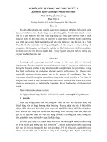
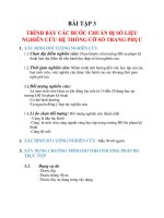
The service brakes are vacuum servo hydraulic brake consisting of
devices such as brake master cylinder, brake booster (hydromaster)
and wheel cylinders and are used to decelerate or stop the traveling
vehicle.
When the pedal is depressed, the depression force is converted into
a hydraulic pressure, which is then amplified by the brake booster
(hydromaster) and acts on the wheel cylinders. The wheel cylinders
press the brake shoes against the brake drums to produce a
frictional force
Rear wheel brake
GENERAL
SERVICE BRAKE
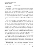
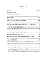
Vacuum Pump
1) The vacuum pump which is installed on the back of the alternator
has its rotor coupled with the alternator shaft so that it rotates
with the alternator. Within its cylindrical housing, as the rotor
rotates, its three movable vanes are made to move toward the
housing inside surface by centrifugal force, thereby producing
pumping action. The resultant vacuum pressure keeps the
inside of the vacuum tank at vacuum.
VB58001
Fluid
reservoir
tank
Brake
master
cylinder
Brake
pedal
Safety cylinder
Brake shoe
Brake drum
Return spring
Wheel cylinder
Front wheel brake
Air line
Fluid line
Air cleaner
Brake booster (hydromaster)
Vacuum tank
Vacuum pump
To atmosphere
Brake
drum
Return spring
Wheel cylinder
Brake shoe
Housing
VB58003
Rotor
BRa-3
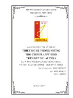
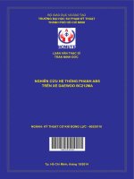
BRAKE BOOSTER (Hydromaster)
1) When brake booster is not operated
Since no fluid pressure acts on the relay valve piston, the
vacuum valve is in opened position and the atmosphere valve
in closed position.
Since the diaphragm air hole is clear, both chambers A and B
of the power cylinder are evacuated and the power piston
pressed toward the chamber B by the return spring.
With the hydraulic piston also pulled an the ball check valve
opened, the brake fluid passes through the center hole of the
hydraulic piston and flows into the hydraulic cylinder.
When the brake booster is not in operation, therefore, the
hydraulic piston serves only as a fluid path.
GENERAL
2) The rotor and housing cylinder are eccentrically arranged and
air from the vacuum tank is taken through the inlet port into the
pump and gradually compressed before it is discharged from
the outlet port. Engine oil enters the pump through the oil port
and keeps the housing oil tight and lubricates and cools the
housing inside. The oil is then discharged from the outlet port
with compressed air and returns to the oil pan.
3) A check valve is provided at the inlet port to prevent air and
engine oil from flowing back from the vacuum pump to the
vacuum tank when the engine is stopped.
VB58005
Suction
Compression
Discharge
Housing
Rotor
Vane
VB58007
Check valve
B
VB58009
Disphragm
Vacuum valve
Atmosphere valve
Relay valve piston
Relay valve section
Ball check valve
Hydraulic piston
Push rod
Return spring
Power piston
A
BRa-4
BRAKE SYSTEM
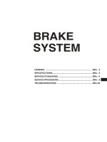
2) When brake booster is operated
When the pedal is depressed, the fluid pressure from the master
cylinder acts on the relay valve piston and hydraulic piston.
The diaphragm, pushed by the fluid pressure acting on the back
surface of the relay valve piston, closes the vacuum valve. As
soon as the vacuum valve is closed, the atmosphere valve is
opened, so the atmospheric air from the air cleaner enters the
power cylinder.
At the time, a pressure difference is produced between the
chambers A and B. The force produced by the pressure
difference overcomes the return spring and the power piston
moves the push rod to push the hydraulic piston.
When the hydraulic piston operates, the ball check valve is
closed and the brake fluid passage between the master cylinder
and the hydraulic cylinder is closed, preventing backflow of the
high pressure fluid generated in the hydraulic cylinder to the
master cylinder and instead transmitting the hydraulic pressure
to the wheel cylinder. The hydraulic pressure developing in the
hydraulic cylinder is the sum of the thrust transmitted from the
power piston to the hydraulic piston and the pressure acting
directly on the hydraulic piston from the brake master cylinder.
VB58011
Atmospheric air pressure
from air cleaner
To wheel
cylinde
(wheel brake)
From master cylinder
To vacuum tank
Relay valve section
BRa-5
SPECIFICATIONS
SPECIFICATIONS
HD120
Unit:mm
Brake type
Front
Rear
Vacuum pump
Type
Delivery rate
Brake booster (hydromaster)
Power cylinder
I.D. x stroke
Hydraulic cylinder
I.D. x stroke
Relay valve piston
O.D.
Safety cylinder
I.D. x stroke
Vacuum tank
Capacity
Wheel brake
Brake drum I.D. (limit)
Brake lining width x thickness (limit)
Front
Rear
Brake shoe clearance
Wheel cylinder I.D.
Front
Rear
Hydro-vacuum servo hydraulic brake acting on all wheels, internal
expansion type
2-leading type
Dual 2-leading type
Vane type
120 cc
241.3 x 163
19.05 x 159
25.4
30 x 32
30lit.
320 (322)
120 x 11.6 (5.0)
150 x 11.6 (5.0)
0.2 ~ 0.3
36.51°
38.1
Vehicle model
Item
BRa-6
BRAKE SYSTEM
SERVICE STANDARDS
SERVICE STANDARDS TABLE
Service brakes
Free travel of brake pedal
Apply 11.8 MPa
(120 kgf/cm²)
fluid pressure to
hydraulic cylinder
and measure amount
fluid pressure
falls in 15 seconds
Pedal shaft to bushing clearance
Return spring
Cylinder to piston clearance
Load/installed length
Valve fitting to relay valve piston
clearance
Hydraulic piston to cylinder clearance
Valve body guide wear depth
Bend of push rod
Brake
pedal
Brake
master
cylinder
Brake
booster
(hydro-
master)
3.5 to 9.2
[20] 0.06 to 0.24
45 N (4.6 kgf)/124.2
[38.1] 0.05 to 0.14
125
54 to 64
(5.5 to 6.5)/30.2
160 to 195
(16.2 to 19.8)/181
[25.4] 0.04 to 0.11
[19.5]0.05 to 0.13
-
0.13 or less
0.4
38 N (3.9 kgf)/124.2
0.2
100
49 (5.0)/30.2
140 (14.5)/181
0.13
0.15
0.5
0.3
Adjust by push
rod of brake
master cylinder
Replace bushing
Replace
Replace piston
Replace
Replace
Replace piston
Replace piston
Replace
Replace
Check and replace
related parts
Remedy and remarks
Limit
Nominal
(Basic diameter in [ ])
Maintenance item
Fluid
tightness
Air tightness
when not
operating
Operation
starting
pressure
Return spring
Valve seat
spring
Piston return
spring
Free lenngth
Load N (kgf)/
installed length
1.47MPa (15kgf/cm²)
or less
3.3kPa (25mmHg)
or less
125 to 225 kPa
(1.3 to 2.3 kgf/cm²)
Set vacuum pressure
in brake booster to
67 kPa (500mmHg).
Slowly apply
presure from
master cylinder and
read pressure
indicated by master
cylinder pressure
gauge when pointer
of vacuum gauge
deflects
Set vacuum pressure
in brake booster to
67 kPa (500 mmHg),
close cock, and
measure amount
vacuum pressure
falls in 15 seconds
105 to 245 kPa
(1.1 to 2.5 kgf/cm²)
BRa-7
Brake
booster
(hydro-
master)
Remedy and remarks
Maintenance item
Set vacuum pressure
in brake booster to
67 kPa (500mmHg).
Slowly depress pedal
of master cylinder
and read pressure
indicated by
hydraulic cylinder
pressure gauge for
master cylinder
pressure gauge
Limit
Nominal
(Basic diameter in [ ])
Operation
at full load
Air tightness
at full load
Set master cylinder
pressure to 490 kPa
(5 kgf/cm²), loosen
air bleeder screw at
end of hydraulic
cylinder to release
master cylinder
pressure, and read
pressure indicated by
wheel cylinder
pressure gauge
Block vacuum supply
at full load and
read amount vacuum
pressure falls in
15 seconds thereafter
Residual
pressure
Replace
Return spring
Safety
cylinder
Load/installed length
3.3 kpa (25mmHg)
or less
78 to 125 kPa
(0.8 to 1.3 kgf/cm²)
Replace
Mark * shows
standard inside
diamter when
oversize lining
is used
Cylindricity
Front
Brake
drum
Brake
shoe
return
spring
Load/installed length
18 to 2 N
(1.81 to 2.21 kgf)/48
Cylinder to piston clearance
[30] 0.06 to 0.12
320
Inside
diameter
Vehicle with 320 drum
0.05
325 N (33 kgf)/192
380 N (39 kgf)/228.4
390 N (40 kgf)/217
380 N (39 kgf)/228.4
420 N (43 kgf)/266.5
12.0
If gaps between
coils or between
coil and cover
are evident
Rear Load/installed length
Brake lining thicknessBrake
shoe
If gaps between
coils or between
coil and cover
are evident
Replace piston
Correct
Free length
180.5
Free length
215.2
Re-
place
Replace
Replace linings
Side shoulder
means werar limit
59 to 155 kPa
(0.6 to 1.6 kgf/cm²)
15 N (1.5 kgf)/48
0.17
322
*321
0.2
5
SERVICE STANDARDS
Check and replace
related parts
1.57 kPa (16 kgf/cm²)/
9.81 to 11.4 kPa
(100 to 116 kgf/cm²)
1.57 kPa (16 kgf/cm²)/
10.1 to 11.1 kPa
(103 to 113kgf/cm²)
BRa-8
BRAKE SYSTEM
Limit
Nominal
(Basic diameter in [ ])
Maintenance item
[34.93] 0.03 to 0.09
[36.51] 0.03 to 0.09
15 N (1.5 kgf)/14.2
0.2
Piston to body
clearance
Wheel
cylinder
Rear
Front
Load/installed
length
Piston to body
clearance
Brake shoe clearance
0.2
12 N (1.2 kgf)/14.2
1.0
Replace
Free length
47.5
Adjust
Re-
place
TIGHTENING TORQUE TABLE
Service brakes
48 (4.9)
72 (7.3)
60 (6.1)
48 (4.9)
25 to 34 (2.5 to 3.5
44 to 64 (4.5 to 6.5)
3.9 to 9.8 (0.4 to 1)
1 to 2 (0.1 to 0.2)
145 to 245 (15 to 25)
59 to 98 (6 to 10)
39 to 54 (4 to 5.5)
15 to 39 (1.5 to 4)
15 to 39 (1.5 to 4)
0.3 to 0.8 (0.03 to 0.08)
6.9 to 8.8 (0.7 to 0.9)
235 to 265 (24 to 27)
78 to 98 (8 to 10)
35 to 53 (3.6 to 5.4)
63 to 94 (6.4 to 9.6)
63 to 94 (6.4 to 9.6)
63 to 94 (6.4 to 9.6)
12 to 16 (1.2 to 1.6)
7.8 to 12 (0.8 to 1.2)
3.9 to 5.9 (0.4 to 0.6)
7.8 to 12 (0.8 to 1.2)
M12 x 1.25
M12 x 1.25
M12 x 1.25
M12 x 1.25
M12 x 1.5
M36 x 1.5
M10 x 1.25
M4 x 10.7
M33 x 1.5
M33 x 1.5
M14 x 1.5
PT 1/2
PT 1/2
M3.5 x 0.6
M10 x 1.25
-
M20 x 1.5
M10 x 1.5
M12 x 1.75
M12 x 1.75
M10 x 1.0
M8 x 1.25
M6 x 1.0
M10 x 1.0
Brake pedal shaft bolt and nut
Brake pedal to master cylinder attaching bolt
and nut
Brake master cylinder bolt
Brake master cylinder push rod adjusting nut
Valve fitting
Hook bolt and nut
Valve body screw
Cylinder cap
Cylinder lock nut
Power piston nut
Elbow assembly
Hose connector
Poppet valve assembly nut
Air bleeder screw
Cylinder cap
Check bolt and nut
Brake master cylinder nipple
Safety cylinder
Brake booster
(hydromaster)
Brake pedal
Wheel brake
Wheel
cylinder bolt
Front
Rear
Pipe assembly tightening
Front
Pipe connec-
tor bolt
Pipe clamp bolt
Bleeder screw
Vehicle with 320 drum
Location tightened
Tightening torque
Nm (kgfm)
Screw size
O.D. x pitch(mm)
Remedy and remarks
BRa-9
5.9 to 9.8 (0.6 to 1)
12 to 16 (1.2 to 1.6)
19 to 25 (1.9 to 2.6)
M6 x 1.0
M10 x 1.0
M12 x 1.0
Wheel brake
Location tightened
Screw size
O.D. x pitch
(mm)
Tightening torque
Nm (kgfm)
Wheel cylinder
Brake pipe tightening
Stop perspring screw
4.76
6.35
SERVICE PROCEDURE
BRAKE SYSTEM DIAGRAM
13. Magnetic valve
14. Exhaust brake valve
15. Oil reservoir
16. Low air pressure switch
17. Remote chamber
SERVICE PROCEDURE
5TBR-005
1
2
3
8
14
13
6
16
7
5
10
12
17
AIR LINE
OIL LINE
9
11
15
11
11
4
1. Air compressor
2. Air drier
3. Fuzzy tank
4. Protection valve
5. Air reservoir
6. Safety valve
7. Drain valve
8. Air gauge
9. Dual brake valve
10. Parking brake valve
11. Air master
12. Quick release valve
BRa-10
BRAKE SYSTEM
1. Vacuum housing
2. Rotor
3. Vane
4. Plate
Reverse the disassembly procedure to assemble.
NOTE
When reassembling, check the parts for metal
dust and other foreign matter.
Ultimate vacuum
91 kPa (680 mmHg) or more
3000 rpm
Vacuum
Speed
Nominal value
73 kPa (550 mmHg) or more
1500 rpm
80 kPa (600 mmHg) or more
3000 rpm
Vacuum
Speed
At
low
speed
Vacuum
Speed
Nominal value
At
low
speed
Evacuation characteristic after 20 seconds (with 10 lit. tank
load)
VACUUM PUMP
Disassembly, inspection and reassembly
VB58015
Testing
a) Set up as illustrated and turning the alternator pulley, measure
performance of the vacuum pump. If the measured value is less
than the nominal value, disassemble and check for vane damage,
housing, rotor and plate contact surface damage. Replace if any
defect is found.
BRAKE FLUID TANK
Inspection of reed switch function
1) Draining of brake fluid
a) Remove the radiator grille from the front of the cab and
remove the brake fluid pipes for brake and clutch.
NOTE
Brake fluid will mar the paint. Wipe out quickly if spilled.
VB58017
1
2
3
4
Alternator
Wear,
damage
Spindle wear
10 lit. vacuum tank
Engine oil
Alternator
Vacuum
pump
For clutch
VB58019
Fro brake
BRa-11
2) Inspection
Check that the warning lamp in the meter cluster lights up when
the brake fluid level falls to the "L" level. If not, replace the brake
fluid tank assembly.
NOTE
Check with the engine running.
L level
SERVICE PROCEDURE
b) With one end of the removed pipes placed in a container,
depress the brake pedal repeatedly until the fluid level in the
brake fluid tank falls to "L" level line.
BRAKE PEDAL
Removal
1) Depress the brake pedal and clutch pedal repeatedly to drain
brake fluid from the brake fluid tank.
2) Remove the meter hood, meter cluster, instrument corner,
panel an instrument control panel side cover.
VB58021
VB58023
VB58025
Brake pedal
Brake fluid tank
Brake pedal
bracket, LH
Stop lamp switch
Brake hose
Brake pipe
BRa-12
BRAKE SYSTEM
Disassembly, inspection and correction
Disassembly sequence
1. Return spring
2. Bolt
3. Brake master cylinder
4. Brake pedal
5. Brake pedal
6. Pedal pad
7. Bushing
8. Pedal shaft
9. Brake pedal bracket, RH
10. Stop lamp switch
11. Meter cluster bracket
BD Basic Diameter
NV Nominal Value
L Limit
VB58027
Clearance between pedal
shaft and bushing
BD 20
NV 0.06 to 0.24
L 0.4
Deterioration of spring
Load/installed length
NV 45N (4.6 kgf)/124.2
L 38N (3.9 kgf)/124.2
1
2
3
4
5
6
7
8
9
10
11
BRa-13
1) Rotate the stop lamp switch to adjust the brake pedal pad center
position (point Z) to the dimension marked *, and then secure it
with the lock nut.
At this point, check to ensure that the stop lamp switch is in the
OFF state.
2) Check to ensure that when the brake pedal is depressed all the
way, the full stroke is 200mm.
3) Rotate the brake master cylinder push rod to adjust the free
travel of the brake pedal pad center position (point Z) to 3 to
9mm, and tighten the lock nut to the specified torque.
4) After adjustments, remove the air from inside the brake system
and clutch system (refer to Group 41 clutch). After bleeding,
depress the brake pedal several times to check for air leaks from
the brake pipe and brake hose connections.
5) Clearance between brake pedal and floor board
Start the engine and depress the brake pedal by 590N (60kgf)
to check that the clearance between the brake pedal and floor
board is 65mm or more.
60 Nm
(6.1 kgfm)
Floor board
SERVICE PROCEDURE
Reassembly and adjustment
VB58029
VB58031
1
2
3
4
5
6
78
9
10
11
Apply grease.
72 Nm
(7.3 kgfm)
48 Nm
(4.9 kgfm)
Section A-A
48 Nm
(4.9 kgfm)
*232mm
*273mm
Stroke 200mm
Z
A
Assembly sequence
11→10→9→8→4→3→2→1
5→6→7
↑
590 N (60 kgf)
65 mm or more
BRa-14
BRAKE SYSTEM
BRAKE MASTER CYLINDER
Disassembly and Inspection
Disassembly sequence
1. Push rod complete
2. Boot
3. C-ring
4. Piston complete
5. Nipple
6. Gasket
7. Cylinder
BD Basic Diameter
NV Nominal Value
L Limit
Free length
NV 125
L 100
Deterioration of spring
Damage
VB58033
Reassembly
NOTE
Apply an ample amount of assemblng oil (NA-166M or equivalent) to cylinder
bore and the entire periphery of secondary cup of piston complete.
Apply grease
(rubber grease)
VB58035
1
2
3
4
5
6
7
Clearance between piston and cylinde
BD 38.1
NV 0.05 to 0.14
L 0.2
Wear, damage,
deformation
Assembly sequence
7
→→
→→
→6
→→
→→
→5
→→
→→
→4
→→
→→
→3
→→
→→
→2
→→
→→
→1
Repair kit:
Brake master cylinder kit.
1
2
3
4
5
6
7
25 to 34 Nm
(2.5 to 3.5 kgfm)
BRa-15
SERVICE PROCEDURE
VB58037
Removal and installation
NOTE
When the oil pipe is removed, use care to make sure that brake
fluid is not split on the frame or bracket.
Disassembly, inspection and correction
NOTE
1. Before disassembly, remove dirt and dust from the surface
and use care not to allow foreign matter, dust, dirt or water
to enter.
2. Put alignment marks before disassembly.
3. Never immerse rubber parts in cleaning solvent.
1) For inspection and correction, disassemble the brake booster
into the relay valve piston section, the hydraulic cylinder section,
the power cylinder section and the end plate section.
2) Wipe or wash to clean to disassembled parts as described
below.
a) Rubber parts or parts containing rubber parts
Wipe with cloth wetted by brake fluid or alcohol.
b) Metallic parts
Clean with cleaning fluid (trichlene or metal cleanser), dry
with compressed air and completely remove cleaning fluid.
BRa-16
BRAKE SYSTEM
Disassembly sequence
1. Retaining ring
2. Pipe and cover assembly
3. Gasket
4. Spring
5. Valve body
6. Valve seat spring
7. Diaphragm assembly
8. Gasket
9. Nut
10. Gasket
11. Poppet
12. Air valve
13. Vacuum valve assembly
14. Elbow assembly
43. Hose connector
44. Plug
45. O-ring
46. Push rod nut
47. Washer
48. Piston plate
49. Rubber packing
50. Gasket
51. Piston plate
52. Push rod assembly
53. Clamp
54. Hose
55. Cylinder shell assembly
15. Valve fitting
16. O-ring
17. Retaining ring
18. Relay valve piston
19. Cup packing
20. Cylinder
21. Cap
22. Gasket
23. Retaining ring
24. Washer
25. Spring
26. Outlet valve assembly
27. Plug
28. Lock nut
Repair kit:
hydromaster kit
VB58039
Rust on piston outside surface
and valve fitting inside surface
29. Gasket
30. Straight pin
31. Hydraulic piston assembly
32. Cup packing
33. Hook bolt
34. End plate assembly
35. Return spring
36. Retaining ring
37. Washer
38. Retainer
39. Cup packing
40. Washer
41. Oil seal
42. Gasket
Clearance between valve fitting
and relay vlave piston
BD 25.4
NV 0.04 to 0.11
L 0.13
Load/installed length
NV 54 to 64
(5.5 to 6.5 kgf)/30.2
L 49 N (5.0 kgf)/30.2
Deterioration of spring
Clearance between hydraulic
piston and cylinder
BD 19.05
NV 0.05 to 0.13
L 0.15
Rust, damage
Guide section
wear depth
L 0.5
Corrosion of guide
section inside surface
Bend of push rod
NV 0.13 or less
L 0.3
Load/installed length
NV 160 to 195N
(16.2 to 19.8 kgf)/181
L 140 N (14.5 kgf)/181
Deterioration of spring
For parts with an encircled
number, refer to Disassembly
Procedure that follows.
1
2
3
4
6
7
8
9
11
12
13
14
15
16
17
18
19
5
10
20
21
22
23
24
25
26
27
28
29
30
31
32
33
34
35
36
37
38
39
40
41
42
43
44
45
46
47
48
49
50
47
51
52
53
54
55
53
BRa-17
SERVICE PROCEDURE
Work Bench
Retaining
ring
Box
NOTE
1. Before disassembly, remove dirt thoroughly from the out-
side of the hydromaster.
2. Before disassembly, put matching marks on mating
sections.
3. Wipe or wash clean the disassembled parts as described
below.
a) Rubber parts and components with rubber parts.
Wipe the parts using clutch wetted with brake fluid or
alcohol.
b) Metal parts
Wash in cleaning agent (trichlene or metachlene) and
remove cleaning agent completely using the com-
pressed air and dry.
4. Check rubber parts visually for damage, wear, swelling,
etc. and replace them if any defect is found.
Disassembly Procedure
1) Fixing of brake booster
Hold the special tool, Work Bench, in a vice and install four hook
bolts of the brake booster, aligning with the guide position of the
work bench.
3) Removal and installation of relay valve section valve fitting
2) Remove and installation of relay valve section retaining ring
VB58041
VB58043
VB58045
Pliers
Hydromaster
Hook bolt
Guide
BRa-18
BRAKE SYSTEM
Pliers
Hook clamp
Needle
4) Removal of hydraulic cylinder
Loosen the lock nut and then loosen the cylinder by holding it
with the special tool, Spanner, on flats.
5) Removal of retaining ring from outlet valve
6) Removal of hydraulic piston
a) When compressed air is not used
With the return spring compressed using the special tool,
Hook Clamp. Remove the straight pin from the hydraulic
piston using a needle or the like.
b) When compressed air is used
With compressed air supplied through the cylinder shell
pipe to push to the hydraulic piston, remove the straight pin
from the hydraulic piston using a needle or the like.
VB58047
VB58049
VB58051
VB58053
(2) Loosen after loosening
lock nut.
(1) First loosen
Lock nut
Spanners
Needle
Return spring
Apply compressed
air
Hydraulic
piston
BRa-19
SERVICE PROCEDURE
7) Remove of push rod nut from power piston
With the special tool, Ring Assembly, held in a vice, install the
power piston, aligning its push rod nut with the flat portion of the
ring assembly. Then align the push rod nut with the flat portion
of the special tool. Socket, and remove the push rod nut.
Ring Assembly
910-11031
VB58055
Power piston
assembly
Socket
910-23531
BRa-20
BRAKE SYSTEM
Assembly sequence
5 → 13 → 12 → 11 → 10 → 9
18 → 19 → 15 → 17 → 16
21 → 27 → 26 → 25 → 24 → 23 → 22 → 20 → 28 → 29
31 → 32
34 → 44 → 41 → 40 → 39 → 37 → 36 → 42 → 43 → 45
52 → 47 → 51 → 50 → 49 → 48 → 47 → 46
55 → 33 35 → 30 → 7 → 8 → 6 → 14 → 54 → 53 → 3 → 4 → 2 →
1
For parts with an encircled number,
refer to Reassembly Procedure that follows.
Reassembly
VB58057
Apply rubber grease
Apply THREEBOND
(1324 or equivalent) to
threaded portion, tighten
nut to 0.3 to 0.8 Nm
(0.03 to 0.08 kgfm), and
then crush thread.
44 to 64 Nm
(4.5 to 6.5 kgfm)
6.9 to 8.8 Nm
(0.7 to 0.9 kgfm)
1 to 2 Nm
(0.1 to 0.2 kgfm)
6.9 to 8.8 Nm
(0.7 to 0.9 kgfm)
145 to 245 Nm
(15 to 25 kgfm)
59 to 98 Nm
(6 to 10 kgfm)
15 to 39 Nm
(1.5 to 4 kgfm)
3.9 to 9.8 Nm
(0.4 to 1 kgfm)
39 to 54 Nm
(4 to 5.5 kgfm)
(After tihtening,
stake two places
with puch)
Face convex portion
toward hydraulic cylinder
Apply airmaster paste to
cylinder shell inside
surface and rubber packing.
(Apply sealant to
threaded portion)
Apply brake fluid.
15 to 39 Nm
(1.5 to 4 kgfm)
(Apply sealant to
threaded portion)
1
2
3
4
5
6
7
8
9
10
11
12
13
14
15
16
17
18
19
20
1
21
22
23
24
25
26
27
28
29
31
32
33
34
35
30
36
37
38
39
40
41
42
43
44
45
51
52
53
54
55
46
47
48
49
50
BRa-21
SERVICE PROCEDURE
4) Installation of end plate oil seal
NOTE
When installing, face the oil seal lip toward the hydraulic
cylinder.
Press-fit Bar
Washer
Hydraulic
piston
Reassembly Procedure
1) Installation of power piston section push rod nut
With the special tool, Ring Assembly, held in a vice, install the
power piston, aligning its push rod nut with the flat portion of the
ring assembly.
Install the washer, piston plate, rubber packing, piston plate and
washer over the push rod and tighten the push rod nut to
specified torque using the special tool, Socket.
2) Installation of outlet valve retaining ring
3) Insertion of cup packing into hydraulic piston
VB58059
VB58061
VB58063
VB58065
Power
piston
assembly
Socket
Ring Assembly
Cap
Outlet valve
spring
Retaining ring
Inset Tool
Cap packing
Cup insert
BRa-22
BRAKE SYSTEM
NOTE
Be sure to use a new poppet valve assembly
Return spring
Stright pin
5) Installation of poppet valve to relay valve section
VB58067
VB58069
VB58071
6) Installation of hydraulic piston
a) When compressed air is not used
With the return spring compressed by the special tool, Hook
Clamp, and the hydraulic piston and push rod holes aligned,
insert the straight pin.
b) When compressed air is used
With the push rod pushed up by compressed air supplied
through the cylinder shell pipe, align the hydraulic piston
and push rod holes and insert the straight pin.
Nut
Gasket
Poppet
Air valve
Valve
body
Vacuum valve
assembly
Apply adhesive
(THREEBOND 1324 or
equivalent) to
threads
Torque Driver
0.3 to 0.8 Nm
(0.03 to 0.08 kgfm)
Tighten nut to the
specified torque
using the special
tool, Torque Driver
Crash the threads
with pliers or
similar tool.
Straight pin
Hydraulic piston
Hook Clamp
Push rod
Supply compressed
air
Hydraulic
piston
BRa-23
SERVICE PROCEDURE
Spanner
7) Installation of hydraulic cylinder
Tighten the lock nut, making sure that the cap plug and the end
plate plug are 30° out of alignment.
VB58073
30°
Plug
Cylinder
Nut
Plug
Box
910-21981
Guide Pin
VB58077
VB58079
8) Installation of valve fitting
9) Installation of valve body
Screw Valve body
Gasket
Spring
Diaphragm assembly
BRa-24
BRAKE SYSTEM
Inspection after installation
1) Performance check
Simple Test as installed on Vehicle
This is a check method without use of instruments. If there is any
doubt to the test results, check performance of individual units
using a tester.
a) Overall check
With the brake booster negative pressure set at 0, depress
the brake pedal as you would in ordinary braking and start
the engine and run idle. If the brake pedal moves down
slightly after about two or three seconds, the brake booster
is performing well.
b) Oil tightness check
With the engine running at idle, depress the brake pedal
fully, if the pedal is pushed back, the hydraulic piston cup
and ball check valve are not oil tight.
c) Air tightness check of poppet valve (atmospheric air valve)
With the engine running at idle, put a thread near the poppet
valve atmosphere side pipe without depressing the brake
pedal.
If the thread is drawn in, the poppet valve atmospheric air
valve is leakly.
Then depress the brake pedal. If the thread is rapidly drawn
in at the moment, the relay valve piston and poppet valve
are performing well.
d) Poppet valve (vacuum valve) and rubber packing check
With the engine running at idle, depress the brake pedal. If
you feel suction at your finger applied to the end of atmo-
spheric air valve side pipe of the poppet valve, the poppet
valve vacuum valve or the power cylinder rubber packing is
not air tight.
VB58081
BRa-25
SERVICE PROCEDURE
2) Performance check
Performance check of brake booster proper
Check the body performance in details using the Stationary Tester (Jidosha Kiki Part No.911-0020).
After all preparations for the test have been completed, bleed the fluid pressure system and test the following items.
If the results of tests show values out of the assembly standard or limit, check and replace related parts.
To vacuum pump
VB58075
Apply fluid pressure of 11.8 MPa (120 kgf/cm²) (PG2)
to hydraulic cylinder and measure the amount of pressure
drop in 15 seconds.
(In this test no vacuum state is created in brake booster.)
1470 kPa (15 kgf/cm²)
or less
3.3 kPa (25 mmHg)
or less
Set vacuum pressure in brke booster to 67 kPa
(500 mmHg), close cock, and measure amount of vacuum
pressure falls in 15 seconds.
Vacuum gauge (VG1)
Set vacuum pressure in brake booster to 67 kPa
(500 mmHg). Gradually apply pressure from master cylinder
and read pressure indicated by mastr cylinder side
pressure gauge (PG1) when pointer of vacuum gauge
(VG1) swings.
Set vacuum pressure in brake booster to 67 kPa (500 mmHg).
Slowly depress pedal of master cylinder and read
pressure indicated by hydraulic cylinder side pressure
gauge (PG2) for master cylinder side pressure gauge (PG1).
During operation at full load, cut off vacuum supply and
read amount of vacuum pressure falls in 15 seconds
thereafter. Vacuum gauge (VG1)
Set pressure of master cylinder to 490 kPa (5 kgf/cm²) (PG1),
loosen air bleeder screw at end of hydraulic cylinder,
release master cylinder side pressure, and read pressure
indicated by wheel cylinder side pressure gauge (PG2).
125 to 225 kPa
(1.3 to 2.3 kgf/cm²)
3.3 kPa (25 mmHg)
or less
78 to 125 kPa
(0.8 to 1.3 kgf.cm²)
-
-
105 to 245 kPa
(1.1 to 2.5 kgf.cm²)
-
Assembly standard Limit
Test item
Fluid
tightness
Test condition
Residual
pressure
Air tightness
at full load
Operation
start
pressure
Operation at
full load
Air tightness
when not in
operation
1570 kPa (16 kgf/cm²)
10.1 to 11.1 MPa
(103 to 113 kgf/cm²)
59 to 155 kPa
(0.6 to 1.6 kgf/cm²)
1570 kPa (16 kgf/cm²)
9.81 to 11.4 MPa
(100 to 116 kgf/cm²)
Pressure gauge (PG2)
Wheel cylnder
Pressure gauge (PG1)
From master cylinder
Vacuum gauge (VG1)
Cock Control valve