Classic 1785 PLC 5 programmable controllers users manual
Bạn đang xem bản rút gọn của tài liệu. Xem và tải ngay bản đầy đủ của tài liệu tại đây (1.38 MB, 186 trang )
User
Manual
Classic 1785 PLCĆ5
Programmable
Controllers
(1785ĆLT,
ĆL
T2, ĆLT3, ĆL
T4)
AllenĆBradley
Because of the variety of uses for the products described in this
publication, those responsible for the application and use of this control
equipment must satisfy themselves that all necessary steps have been
taken to assure that each application and use meets all performance and
safety requirements, including any applicable laws, regulations, codes,
and standards.
The illustrations, charts, sample programs, and layout examples shown in
this guide are intended solely for purposes of example. Since there are
many variables and requirements associated with any particular
installation, Allen-Bradley does not assume responsibility or liability
(to include intellectual property liability) for actual use based on the
examples shown in this publication.
Allen-Bradley publication SGI-1.1, Safety Guidelines for the Application,
Installation, and Maintenance of Solid State Control (available from your
local Allen-Bradley office), describes some important differences between
solid-state equipment and electromechanical devices that should be taken
into consideration when applying products such as those described in
this publication.
Reproduction of the contents of this copyrighted publication, in whole
or in part, without written permission of Allen-Bradley Company, Inc.,
is prohibited.
Throughout this manual we use notes to make you aware of
safety considerations:
ATTENTION: Identifies information about practices or
circumstances that can lead to personal injury or death,
property damage, or economic loss.
Attention statements help you to:
identify a hazard
avoid the hazard
recognize the consequences
Important: Identifies information that is critical for successful application
and understanding of the product.
Important User Information
Summary of Changes
i
Summary of Changes
This manual has been revised to cover only Classic PLC-5 programmable
controllers: PLC-5/10, -5/12, -5/15, and -5/25.
It has also been revised to include the accompanying design worksheets
that were formerly available as a separate publication: 1785-5.2. This
separate publication is no longer available; see Appendix B for these
worksheets.
For information about Enhanced and Ethernet PLC-5 processors, see the
Enhanced and Ethernet PLC-5 Programmable Controllers User Manual,
publication 1785-6.5.12.
Summary of Changes
i
. . . . . . . . . . . . . . . . . . . . . . . . . . . .
Classic PLCĆ5 Programmable Controllers
iii
. . . . . . . . . . . . .
Purpose
of this Manual
iii
. . . . . . . . . . . . . . . . . . . . . . . . . . . . . . . .
Manual Organization
iv
. . . . . . . . . . . . . . . . . . . . . . . . . . . . . . . . .
How to Use this Manual
iv
. . . . . . . . . . . . . . . . . . . . . . . . . . . . . . .
Understanding
Y
our System 1Ć1. . . . . . . . . . . . . . . . . . . . . . .
Using this Chapter 1Ć1. . . . . . . . . . . . . . . . . . . . . . . . . . . . . . . . . . .
Understanding the Terms Used in this Chapter 1Ć1
. . . . . . . . . . . . . . .
Designing Systems 1Ć2
. . . . . . . . . . . . . . . . . . . . . . . . . . . . . . . . . .
Preparing Your Functional Specification 1Ć3
. . . . . . . . . . . . . . . . . . . .
Introducing Classic PLCĆ5 Processor Modules 1Ć5
. . . . . . . . . . . . . . .
Using the Classic PLCĆ5 Processor as a Remote I/O Scanner 1Ć8
. . . .
Using the Classic PLCĆ5 Processor as a Remote I/O Adapter 1Ć9
. . . .
Choosing Hardware 2Ć1. . . . . . . . . . . . . . . . . . . . . . . . . . . . . .
Chapter
Objectives
2Ć1. . . . . . . . . . . . . . . . . . . . . . . . . . . . . . . . . . .
Selecting
I/O Modules
2Ć1. . . . . . . . . . . . . . . . . . . . . . . . . . . . . . . . .
Selecting I/O Adapter Modules 2Ć4
. . . . . . . . . . . . . . . . . . . . . . . . . .
Selecting
I/O Chassis
2Ć6. . . . . . . . . . . . . . . . . . . . . . . . . . . . . . . . .
Selecting an Operator Interface 2Ć6
. . . . . . . . . . . . . . . . . . . . . . . . . .
Choosing a Classic PLCĆ5 Processor for Your Application 2Ć9
. . . . . . .
Selecting Power Supplies 2Ć9
. . . . . . . . . . . . . . . . . . . . . . . . . . . . . .
Selecting Memory Modules 2Ć13
. . . . . . . . . . . . . . . . . . . . . . . . . . . . .
Selecting a Replacement Battery 2Ć13
. . . . . . . . . . . . . . . . . . . . . . . . .
Selecting
Complementary I/O
2Ć13. . . . . . . . . . . . . . . . . . . . . . . . . . .
Selecting a PLCĆ5 Processor Backup System 2Ć14
. . . . . . . . . . . . . . .
Selecting Link Terminators 2Ć15
. . . . . . . . . . . . . . . . . . . . . . . . . . . . .
Connecting a Programming Terminal to a Processor Module 2Ć15
. . . . .
Choosing Cables 2Ć15
. . . . . . . . . . . . . . . . . . . . . . . . . . . . . . . . . . . .
Placing System Hardware 3Ć1. . . . . . . . . . . . . . . . . . . . . . . . .
Chapter
Objectives
3Ć1. . . . . . . . . . . . . . . . . . . . . . . . . . . . . . . . . . .
Determining the Proper Environment 3Ć1
. . . . . . . . . . . . . . . . . . . . . .
Protecting Your Processor 3Ć4
. . . . . . . . . . . . . . . . . . . . . . . . . . . . .
Avoiding Electrostatic Damage 3Ć4
. . . . . . . . . . . . . . . . . . . . . . . . . .
Laying
Out Y
our Cable Raceway 3Ć4. . . . . . . . . . . . . . . . . . . . . . . . .
Planning
Cabling
3Ć5. . . . . . . . . . . . . . . . . . . . . . . . . . . . . . . . . . . .
Laying Out the Backpanel Spacing 3Ć6
. . . . . . . . . . . . . . . . . . . . . . .
Grounding
Configuration
3Ć7. . . . . . . . . . . . . . . . . . . . . . . . . . . . . . .
Table of Contents
Table of Contentsii
Assigning Addressing Modes, Racks, and Groups 4Ć1. . . . . .
Chapter
Objectives
4Ć1. . . . . . . . . . . . . . . . . . . . . . . . . . . . . . . . . . .
Placing
I/O Modules in Chassis
4Ć1. . . . . . . . . . . . . . . . . . . . . . . . . .
Understanding the Terms Used in this Chapter 4Ć2
. . . . . . . . . . . . . . .
Choosing the Addressing Mode 4Ć3
. . . . . . . . . . . . . . . . . . . . . . . . . .
Assigning Racks 4Ć9
. . . . . . . . . . . . . . . . . . . . . . . . . . . . . . . . . . . .
Addressing
Complementary I/O
4Ć12. . . . . . . . . . . . . . . . . . . . . . . . . .
Choosing
Communication
5Ć1. . . . . . . . . . . . . . . . . . . . . . . . .
Chapter
Objectives
5Ć1. . . . . . . . . . . . . . . . . . . . . . . . . . . . . . . . . . .
Identifying Classic PLCĆ5 Processor Channels/Connectors 5Ć1
. . . . . .
Configuring
Communication for Y
our Processor 5Ć3. . . . . . . . . . . . . .
Configuring a DH+ Link 5Ć3
. . . . . . . . . . . . . . . . . . . . . . . . . . . . . . . .
Connecting a DH+ Link to Data Highway 5Ć10
. . . . . . . . . . . . . . . . . . .
Choosing Programming Terminal Connection 5Ć10
. . . . . . . . . . . . . . . .
Planning
Y
our System Programs 6Ć1. . . . . . . . . . . . . . . . . . . .
Chapter
Objectives
6Ć1. . . . . . . . . . . . . . . . . . . . . . . . . . . . . . . . . . .
Planning Application Programs 6Ć1
. . . . . . . . . . . . . . . . . . . . . . . . . .
Using SFCs with PLCĆ5 Processors 6Ć1
. . . . . . . . . . . . . . . . . . . . . . .
Preparing the Programs for Your Application 6Ć3
. . . . . . . . . . . . . . . .
Addressing Data T
able Files
6Ć7. . . . . . . . . . . . . . . . . . . . . . . . . . . .
Using the Processor Status File 6Ć9
. . . . . . . . . . . . . . . . . . . . . . . . . .
Selecting Interrupt Routines 7Ć1. . . . . . . . . . . . . . . . . . . . . . .
Chapter
Objectives
7Ć1. . . . . . . . . . . . . . . . . . . . . . . . . . . . . . . . . . .
Using Programming Features 7Ć1
. . . . . . . . . . . . . . . . . . . . . . . . . . .
Writing
a Fault Routine
7Ć3. . . . . . . . . . . . . . . . . . . . . . . . . . . . . . . .
Understanding ProcessorĆDetected Major Faults 7Ć11
. . . . . . . . . . . . .
Transferring Discrete and BlockĆTransfer Data 8Ć1. . . . . . . . .
Chapter
Objectives
8Ć1. . . . . . . . . . . . . . . . . . . . . . . . . . . . . . . . . . .
Transferring Data Using Adapter Mode 8Ć1
. . . . . . . . . . . . . . . . . . . .
Programming Discrete Transfer in Adapter Mode 8Ć4
. . . . . . . . . . . . .
Programming Block Transfer in Adapter Mode 8Ć7
. . . . . . . . . . . . . . .
Transferring Data Using Scanner Mode 8Ć16
. . . . . . . . . . . . . . . . . . . .
Programming Discrete Transfer in Scanner Mode 8Ć16
. . . . . . . . . . . . .
Programming Block Transfer in Scanner Mode 8Ć17
. . . . . . . . . . . . . . .
Programming Considerations 8Ć21
. . . . . . . . . . . . . . . . . . . . . . . . . . .
Table of Contents iii
Calculating
Program T
iming 9Ć1. . . . . . . . . . . . . . . . . . . . . . . .
Chapter
Objectives
9Ć1. . . . . . . . . . . . . . . . . . . . . . . . . . . . . . . . . . .
Introduction to Classic PLCĆ5 Processor Scanning 9Ć1
. . . . . . . . . . . .
I/O ScanningĊDiscrete and Block Transfer 9Ć5
. . . . . . . . . . . . . . . . .
Instruction Timing and Memory Requirements 9Ć7
. . . . . . . . . . . . . . .
Program Constants 9Ć13
. . . . . . . . . . . . . . . . . . . . . . . . . . . . . . . . . .
Direct and Indirect Elements 9Ć13
. . . . . . . . . . . . . . . . . . . . . . . . . . . .
Maximizing System Performance 10Ć1. . . . . . . . . . . . . . . . . . . .
Chapter
Objectives
10Ć1. . . . . . . . . . . . . . . . . . . . . . . . . . . . . . . . . . .
Components of Throughput 10Ć1
. . . . . . . . . . . . . . . . . . . . . . . . . . . . .
Input and Output Modules Delay 10Ć1
. . . . . . . . . . . . . . . . . . . . . . . . .
I/O Backplane Transfer 10Ć2
. . . . . . . . . . . . . . . . . . . . . . . . . . . . . . . .
Remote
I/O Scan T
ime 10Ć2. . . . . . . . . . . . . . . . . . . . . . . . . . . . . . . .
Processor Time 10Ć6
. . . . . . . . . . . . . . . . . . . . . . . . . . . . . . . . . . . . .
Calculating Throughput 10Ć6
. . . . . . . . . . . . . . . . . . . . . . . . . . . . . . . .
Selecting Switch Settings AĆ1. . . . . . . . . . . . . . . . . . . . . . . . .
Chassis Backplane with Classic PLCĆ5 Processor AĆ1. . . . . . . . . . . . .
Chassis Backplane with Adapter Module AĆ2
. . . . . . . . . . . . . . . . . . .
Chassis Configuration Plug for Power Supply AĆ3
. . . . . . . . . . . . . . . .
Remote I/O Adapter Module 1771ĆASB Series C without
Complementary I/O
AĆ4. . . . . . . . . . . . . . . . . . . . . . . . . . . . . . . .
Remote I/O Adapter Module 1771ĆASB Series C with
Complementary I/O
AĆ6. . . . . . . . . . . . . . . . . . . . . . . . . . . . . . . .
SW1 AĆ7
. . . . . . . . . . . . . . . . . . . . . . . . . . . . . . . . . . . . . . . . . . . . .
AdapterĆMode ProcessorsĊSW2 in a PLCĆ5 or Scanner Module AĆ8
. .
AdapterĆMode ProcessorsĊSW2 in a PLCĆ2/20, Ć2/30,
or Sub I/O Scanner Module System AĆ9
. . . . . . . . . . . . . . . . . . . .
AdapterĆMode ProcessorsĊSW2 in a PLCĆ3 or PLCĆ5/250
System with 8ĆWord Groups AĆ10
. . . . . . . . . . . . . . . . . . . . . . . . .
AdapterĆMode ProcessorsĊSW2 in a PLCĆ3 or PLCĆ5/250
System with 4ĆWord Groups AĆ11
. . . . . . . . . . . . . . . . . . . . . . . . .
SW3 AĆ12
. . . . . . . . . . . . . . . . . . . . . . . . . . . . . . . . . . . . . . . . . . . . .
Design Worksheets BĆ1. . . . . . . . . . . . . . . . . . . . . . . . . . . . . .
Conventions Used in These Worksheets BĆ1. . . . . . . . . . . . . . . . . . .
Prepare
a Functional Specification
BĆ2. . . . . . . . . . . . . . . . . . . . . . . .
Determine Control Strategy BĆ4
. . . . . . . . . . . . . . . . . . . . . . . . . . . . .
Identify Chassis Locations BĆ6
. . . . . . . . . . . . . . . . . . . . . . . . . . . . .
Select Module T
ypes and List I/O Points
BĆ7. . . . . . . . . . . . . . . . . . . .
Total
I/O Module Requirements
BĆ9. . . . . . . . . . . . . . . . . . . . . . . . . .
Assign I/O Modules to Chassis and Assign Addresses BĆ10
. . . . . . . . . .
Select Adapter Modules BĆ12
. . . . . . . . . . . . . . . . . . . . . . . . . . . . . . .
Place System Hardware BĆ14
. . . . . . . . . . . . . . . . . . . . . . . . . . . . . . .
Table of Contentsiv
Configure
Switch Settings
BĆ15. . . . . . . . . . . . . . . . . . . . . . . . . . . . . .
Determine Communication Requirements BĆ17
. . . . . . . . . . . . . . . . . . .
Select a Classic PLCĆ5 Processor BĆ21
. . . . . . . . . . . . . . . . . . . . . . . .
Select Power Supplies BĆ23
. . . . . . . . . . . . . . . . . . . . . . . . . . . . . . . .
Choose a Programming Terminal BĆ24
. . . . . . . . . . . . . . . . . . . . . . . . .
Select Programming T
erminal Configuration
BĆ25. . . . . . . . . . . . . . . . .
Select Operator Interface BĆ26
. . . . . . . . . . . . . . . . . . . . . . . . . . . . . .
Develop Programming Specifications BĆ28
. . . . . . . . . . . . . . . . . . . . . .
Preface
iii
Classic PLCĆ5 Programmable Controllers
Your Classic PLC-5 Programmable Controllers documentation is organized
into manuals according to the tasks you perform. This organization lets
you easily find the information you want without reading through
information that is not related to your current task. The arrow in Figure 1
points to the book you are currently using.
Figure 1
Classic
PLCĆ5 Programmable Controllers Documentation Library
6200 or AI Series Software
Reference
Instruction Set
Instruction execution,
parameters, status
bits and examples
1785 PLCĆ5
Programmable Controllers
Quick Reference
Quick access to switches,
status bits, indicators,
instructions, SW screens
1785Ć7.1
1785Ć6.6.1
Classic 1785 PLCĆ5
Programmable Controllers
Hardware Installation
How to install and set
switches for chassis,
PLCĆ5 processor, how
to wire and ground
your system
1785Ć6.1
Classic 1785 PLCĆ5
Programmable Controllers
User Manual
1785Ć6.2.1
Explanation of processor
functionality, system
design, and programming
considerations and worksheets
For more information on 1785 PLC-5 programmable controllers or the
above publications, contact your local Allen-Bradley sales office,
distributor, or system integrator.
This manual is intended to help you design a Classic PLC-5 programmable
controller system. Use this manual to assist you in:
selecting the proper hardware components for your system
determining the important features of classic PLC-5 processors and how
to use those features
planning your classic PLC-5 system layout
How to Use
Your Documentation
Purpose
of this Manual
Preface
iv
This manual has ten chapters and two appendices. The following table
lists each chapter or appendix with its corresponding title and a brief
overview of the topics covered in it.
Chapter
/
Appendix
Title Topics Covered
1 Understanding Your System Provides an overview of Classic PLCĆ5 processors in different system configurations. Provides
an introduction to Classic PLCĆ5 processors and their primary features and configurations. Also
provides information on using a Classic PLCĆ5 processor as a remote I/O scanner or a remote
I/O adapter.
2 Choosing Hardware Provides information on your hardware choices when you design a Classic PLCĆ5 processor
system.
3 Placing System Hardware Describes proper environment, Classic PLCĆ5 processor protection, and prevention of
electrostatic damage for your Classic PLCĆ5 programmable controller system. Also covers
raceway and cable layout, backpanel spacing, and grounding configurations.
4 Assigning Addressing Mode,
Rack, and Groups
Describes the I/O addressing modes that you can choose for your chassis. Explains how you
assign group and rack numbers to your I/O chassis. Also covers how you configure
complementary I/O by assigning rack and group addresses.
5 Choosing Communication Identifies each Classic Ć5 processor channel/connector, and explains how to configure your
Classic PLCĆ5 processor. Provides additional information about the Data Highway Plust
(DH+t) link, programming software, and programmingĆterminal connections.
6 Planning Your System Programs Explains the use of sequential function charts (SFCs). Provides guidelines and examples for
preparing system programs. Provides a map of data table files and methods to address the
data table files. Explains how to use the processor status file.
7 Selecting Interrupt Routines Summarizes the conditions for which you would choose fault routines for your application.
Provides a definition of fault routines.
8 Transferring Discrete and
BlockĆTransfer Data
Explains how your CLassic PLCĆ5 processor transfers discrete and blockĆtransfer data in both
scanner and adapter modes.
9 Calculating Program Timing Provides an overview of processor scan timing. Lists execution times and memory
requirements for bit and word instructions as well as file instructions.
10 Maximizing System Performance Explains how to calculate throughput, and provides methods for optimizing I/O scan time.
A Selecting Switch Settings Describes the switch settings for configuring a Classic PLCĆ5 programmable controller system.
B Design Worksheets Provides worksheets to help the designer plan the system and the installer to install the system.
The following flow chart demonstrates a thought process that you can use
when you plan your Classic PLC-5 programmable controller system.
Manual Organization
How to Use this Manual
Preface
v
System Design
Determined
Select I/O
modules, terminals
Place
hardware
Select I/O chassis
Select power supply
Select PLCĆ5 processor
Select batteries and
memory modules
Complementary I/O
selected?
Backup system
selected?
Configure processor
communication
Configure Data
Highway Plus
Select programming
software
Data table layout and
processor status
Use fault routines
Choosing
Hardware
and
Placing
System
Hardware
Choosing
Communication
Assigning
Addressing Mode,
Racks, and Groups
I/O update and ladder
program scan times
Planning Your
System Programs
Calculating
Program Timing
and Maximizing
System
Performance
Transfer data in adapter
and scanner modes
Transferring
Discrete and
Block Data
Design SFCs
Select adapter modules
Assign
addressing
Since your decisions cannot always be made as a part of a strictly linear
process, you can choose to complete tasks in parallel. When you select
your I/O modules, for example, you can also begin to lay out and address
your modules. Consult chapter 3, “Placing System Hardware,” to
determine environmental requirements, enclosures needed, cable layout,
and grounding requirements for your chassis and I/O links. Also, you can
choose to assess block-transfer timing when you determine where you will
place your block-transfer modules (in the processor-resident local I/O
chassis, extended-local I/O chassis, or remote I/O chassis).
Chapter
1
1-1
Understanding Your System
If you want to read about: Go to page:
Terms used in this chapter 1Ć1
Designing systems 1Ć2
Preparing your functional specification 1Ć3
Identifying Classic PLCĆ5 processor features 1Ć5
Using the Classic PLCĆ5 processor as a remote I/O scanner 1Ć8
Using the Classic PLCĆ5 processor as a remote I/O adapter 1Ć9
Become familiar with the following terms and their definitions.
Term Definition
ProcessorĆresident
local I/O chassis
the I/O chassis in which the PLCĆ5 processor is installed
ProcessorĆresident
local I/O
I/O modules located in the same chassis as the PLCĆ5 processor
Remote I/O link a serial communication link between a PLCĆ5 processor port in scanner
mode and an adapter as well as I/O modules that are located remotely
from the PLCĆ5 processor
Remote I/O chassis the hardware enclosure that contains an adapter and I/O modules that
are located remotely on a serial communication link to a PLCĆ5
processor in scanner mode
DiscreteĆtransfer data data (words) transferred to/from a discrete I/O module
BlockĆtransfer data data transferred, in blocks of data up to 64 words, to/from a blockĆ
transfer I/O module (for example, an analog module)
Using this Chapter
Understanding the Terms
Used in this Chapter
Understanding Your System
Chapter 1
1-2
You can use Classic PLC-5 processors in a system that is designed for
centralized control or in a system that is designed for distributed control.
Classic PLCĆ5
Processor
1771ĆASB
Remote I/O
Adapter
1771ĆASB
Remote I/O
Adapter
Remote I/O Link
Programming Terminal
Chassis with Chassis with
Centralized
control
is a
hierarchical system where control
over an entire process is
concentrated in one processor
.
HP 9000
or VAX
Host
Programming
Terminal with
ControlView
Software
DH+ Link
Pyramid
Integrator
Remote I/O Link
PanelView
Operator
Terminal
Series 8600
CNC with
Remote I/O
SLC 5/01 Processor
7Ćslot Modular System
with 1747ĆDCM Module
DH+ Link
Distributed
control
is a system in
which control and management
functions are spread throughout a
plant. Multiple processors handle
the control and management
functions and use a Data
Highway
or a bus system
for communication.
6200 VMS
INTERCHANGE
Software
Programming
Terminal
ControlView
INTERCHANGE
Software
To DECnet
r
18084
Consider the following items as general guidelines when designing
your system.
Will your processor(s) be used in a centralized or distributed system?
What type of process(es) will be controlled by the PLC-5 system?
What processes will be controlled together?
What are the environmental and safety concerns?
What is the flow and functionality of your system?
Designing
Systems
Understanding Your System
Chapter 1
1-3
Determine the general criteria for your system. Use the chapters that
follow to guide you through the criteria and choices for selecting the major
Classic PLC-5 programmable controller system elements, as shown in
Figure 1.1.
Figure 1.1
PLCĆ5
Processor System Design Flow
System Design
Determined
Select I/O
modules, terminals
Place
hardware
Select I/O chassis
Select power supply
Select Classic PLCĆ5
processor
Select batteries and
memory modules
Complementary I/O
selected?
Backup system
selected?
Configure processor
communication
Configure Data
Highway Plus
Select programming
software
Data table layout and
processor status
Use fault routines
Choosing
Hardware
and
Placing
System
Hardware
Choosing
Communication
Assigning
Addressing Mode,
Racks, and Groups
I/O update and ladder
program scan times
Planning Your
System Programs
Calculating
Program Timing
and Maximizing
System
Performance
Transfer data in adapter
and scanner modes
Transferring
Discrete and
Block Data
Design SFCs
Select adapter modules
Assign
addressing
We recommend that you first develop a specification that defines your
hardware selection and your programming application. The specification
is a conceptual view of your system. Use it to determine your:
control strategy
hardware selection, layout, and addressing
sequential function chart (SFC)
special programming features
ladder-logic requirements
Preparing
Y
our
Functional Specification
Understanding Your System
Chapter 1
1-4
Figure 1.2 illustrates a program-development model that you can use.
Figure 1.2
ProgramĆDevelopment
Model
Functional
Specification
Detailed
Anaylsis
(General Conception)
Program
Testing
Acceptance
Development
SignĆoff
This model allows for the interaction of activities at the different levels.
Each section represents an activity that you perform. Prepare a functional
specification to start; then, prepare the detailed analysis.
Based on the detailed analysis, you can also develop your programs, enter
your programs, and test them. When testing is complete, you are ready to
implement the programs in your application. The detailed analysis can be
used as the basis for developing your testing procedures and requirements.
Because the functional specification is well thought out, it can be used as
the program sign-off document.
Functional Specification Content
The functional specification represents a very general view of your process
or a description of operation. Identify the events and the overall order in
which they must occur. Identify the equipment that you will need for your
process/operation. Generally indicate the layout of your system. If your
application requires a distributed control system, for example, indicate
where you will need remote I/O links. Also, you can have a process that is
located close to your processor. The process can require faster update time
than that provided by a remote I/O link, so you can select an extended-
local I/O link for that process.
Important: Choose a communication rate for your remote I/O link at
which every device on the link can communicate.
Understanding Your System
Chapter 1
1-5
The program-development portion of your functional specification can be
in any form: written statement; flowchart; or rough-draft MCPs, SFCs,
and subroutines. Use the form that is most familiar to you. We
recommend, however, that you generate rough-draft SFCs and subroutines
so that you have a better correspondence between your beginning diagrams
and your finished program.
Detailed Analysis
In this phase, you identify the logic needed to plan your programs. This
includes inputs, outputs, specific actions, and transitions between actions
(i.e., the bit-level details needed to write your program).
Program Development
You enter the programs either offline into your computer or online into a
processor. In the next phase, you test the programs that you have entered.
Once testing is complete, your resulting programs should match your
functional specification.
Checking for Completeness
When you complete the functional specification and the detailed analysis,
review them and check for missing or incomplete information such as:
input conditions
safety conditions
startup or emergency shutdown routines
alarms and alarm handling
fault detection and fault handling
message display of fault conditions
abnormal operating conditions
The following is a list of the PLC-5 processors and their catalog numbers.
Processor Catalog Number
PLCĆ5/10t
1785ĆLT4
PLCĆ5/12t
1785ĆLT3
PLCĆ5/15t
1785ĆLT
PLCĆ5/25t
1785ĆLT2
For information on other PLC-5 processors (Enhanced, Ethernet, or
ControlNet), see your Allen-Bradley representative.
Introducing
Classic PLCĆ5
Processor Modules
Understanding Your System
Chapter 1
1-6
Classic PLCĆ5 Family Processor Features
From the family of PLC-5 processors, you can choose the processor(s)
that you need for your application. Features common to all Classic PLC-5
processors are:
same physical dimensions
use of the left-most slot in the 1771 I/O chassis
can use any 1771 I/O module in the processor-resident local I/O chassis
with up to 32 points per module
same programming software and programming terminals
same base set of instructions
ladder programs and SFCs can be used by any of the PLC-5 processors
Check with your Allen-Bradley sales office or distributor if you have
questions regarding any of the features of your PLC-5 processor.
Subprogram Calls
Use a subroutine to store recurring sections of program logic that can be
accessed from multiple program files. A subroutine saves memory
because you program repetitive logic only once. The JSR instruction
directs the processor to go to a separate subroutine file within the logic
processor, scan that subroutine file once, and return to the point
of departure.
For detailed information about how you generate and use subroutines, see
your programming software documentation set.
Sequential Function Charts
Use SFCs as a sequence-control language to control and display the state
of a control process. Instead of one long ladder program for your
application, divide the logic into steps and transitions. A step corresponds
to a control task; a transition corresponds to a condition that must occur
before the programmable controller can perform the next control task. The
display of these steps and transitions lets you see what state the machine
process is in at a given time.
For detailed information about how you generate and use SFCs, see you
programming software.
Ladder Logic Programs
A main program file can be an SFC file numbered 1-999; it can also be a
ladder-logic file program numbered 2-999 in any program file.
Understanding Your System
Chapter 1
1-7
Consider using this technique:
If you are:
SFC
• defining the order of events in a sequential process
Ladder Logic
• more familiar with ladder logic than with programming
languages such as BASIC
• performing diagnostics
• programming discrete control
For detailed information about how you use ladder logic, see your
programming software documentation.
Backup System
The following diagram shows a typical PLC-5 backup system:
HSSL
1771ĆP4S
Power Supply
1785ĆBCM Module
PLCĆ5
Local I/O Chassis
Local I/O Chassis
Remote I/O Link
DH+ LInk
DH+ Link
18691
Remote I/O Chassis Remote I/O Chassis
Remote I/O Link
Processor
1771ĆP4S
Power Supply
1785ĆBCM Module
PLCĆ5
Processor
In a PLC-5 backup system configuration, one system controls the operation
of remote I/O and DH+ communications. This system is referred to as the
“primary system.” The other system is ready to take control of the remote
I/O and DH+ communications in the event of a fault in the primary system.
This is referred to as the “secondary system.”
See chapter 2, “Choosing Hardware,” to select backup system hardware.
See the PLC-5 Backup Communication Module User Manual, publication
1785-6.5.4, for more information on configuring a PLC-5 backup system.
Understanding Your System
Chapter 1
1-8
Use scanner mode whenever you want a Classic PLC-5 processor to scan
and control remote I/O link(s). The scanner-mode processor also acts as a
supervisory processor for other processors that are in adapter mode.
The scanner-mode processor scans the processor memory file to read
inputs and control outputs. The scanner-mode processor transfers
discrete-transfer data and block-transfer data to/from the processor-resident
local rack as well as to/from modules in remote I/O racks.
A PLC-5 processor scans processor-resident local I/O synchronously to the
program scan. A PLC-5 processor scans remote I/O asynchronously to the
program scan, but the processor updates the input/output image data table
from the remote I/O buffer(s) synchronously to the program scan. This
occurs at the end of each program scan.
Remote I/O
Link
Remote I/O
Scan
ProcessorĆResident
Synchronous to
Program Scan
Asynchronous to
Program Scan
OutputInput
Input
Output
Remote
I/O
Buffer
Input
Output
ProcessorĆ
Resident
I/O
ScannerĆMode
PLCĆ5
Processor
Local I/O Scan
The scanner-mode PLC-5 processor can also:
gather data from node adapter devices in remote I/O racks
process I/O data from 8-, 16-, or 32-point I/O modules
address I/O in 2-, 1-, or 1/2-slot I/O groups
support a complementary I/O configuration
support block transfer in any I/O chassis
Configure the PLC-5/15 or -5/25 processor for scanner mode by setting
switch assembly SW1.
Using the Classic PLCĆ5
Processor as a Remote I/O
Scanner
Understanding Your System
Chapter 1
1-9
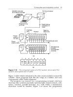
Use a Classic PLC-5 processor (except the PLC-5/10 processor) in adapter
mode when you need predictable, real-time exchange of data between a
distributed control PLC-5 processor and a supervisory processor. You
connect the processors via the remote I/O link (see Figure 1.3). You can
monitor status between the supervisory processor and the adapter-mode
PLC-5 processor at a consistent rate (i.e., the transmission rate of the
remote I/O link is unaffected by programming terminals and other
non-control-related communications).
Figure 1.3
AdapterĆMode
Communication
1
Remote I/O Link
1771
I/O
DL40
Message
Display
Remote I/O Link
Supervisory
Processor
PLCĆ5
Processor
in Adapter
Mode
1
The following programmable controllers can operate as supervisory processors:
PLCĆ2/20t and PLCĆ2/30t processors
PLCĆ3t and PLCĆ3/10t processors
PLCĆ5/11, Ć5/15, Ć5/20, Ć5/25, and Ć5/30 processors as well as PLCĆ5/VMEt processors
PLCĆ5/40, Ć5/40L, Ć5/60, Ć5/60L, and Ć5/80 processors as well as PLCĆ5/40BVt and
PLCĆ5/40LVt processors
PLCĆ5/20Et, Ć5/40Et
PLCĆ5/250t
All PLCĆ5 family processors, except the PLCĆ5/10, can operate as remote I/O adapter modules.
2
2
The PLC-5 processor in adapter mode acts as a remote station to the
supervisory processor. The adapter-mode PLC-5 processor can monitor
and control its processor-resident local I/O while communicating with the
supervisory processor via a remote I/O link.
The supervisory processor communicates with the PLC-5/12, -5/15, or
-5/25 adapter with either eight or four I/O image table words.
A PLC-5 processor transfers I/O data and status data using discrete
transfers and block transfers. You can also use block-transfer instructions
to communicate information between a supervisory processor and an
adapter-mode processor. The maximum capacity per block transfer is
64 words.
Using the Classic PLCĆ5
Processor
as a Remote I/O Adapter
Chapter
2
2-1
Choosing Hardware
Use this chapter to guide you in the selection of system hardware for
your application.
To select: Go to page:
I/O modules 2Ć1
I/O adapters 2Ć4
Chassis 2Ć6
Operator interface 2Ć6
PLCĆ5 processor 2Ć9
Power supplies 2Ć9
Memory modules 2Ć13
Batteries 2Ć13
Complementary I/O 2Ć13
Backup system 2Ć14
Termination resistor 2Ć15
Cables 2Ć15
You select I/O modules to interface your PLC-5 processor with machines
or processes that you have previously determined.
Use the following list and Table 2.A as guidelines for selecting I/O
modules and/or operator control interface(s).
How much I/O is required to control the process(es)?
Where will you concentrate I/O points for portions of an entire process
(when an entire process is distributed over a large physical area)?
What type of I/O is required to control the process(es)?
What is the required voltage range for each I/O module?
What is the backplane current required for each I/O module?
What are the noise and distance limitations for each I/O module?
What isolation is required for each I/O module?
Chapter
Objectives
Selecting I/O Modules
System Design
Determined
Choosing
Communication
Transferring Discrete
and Block Data
Planning Your
System Programs
Calculating Program
Timing
Assigning Addressing
Mode, Racks,
and Groups
Placing System
Hardware
Choosing Hardware
Selecting Interrupt
Routines
Choosing Hardware
Chapter 2
2-2
Table 2.A
Guidelines
for Selecting I/O Modules
Choose this type of
I/O module:
For these types of field devices or operations (examples): Explanation:
Discrete input module
and block I/O module
1
Selector switches, pushbuttons, photoelectric eyes, limit switches,
circuit breakers, proximity switches, level switches, motor starter
contacts, relay contacts, thumbwheel switches
Input modules sense ON/OFF or OPENED/
CLOSED signals. Discrete signals can be either
ac or dc.
Discrete output module
and block I/O module
1
Alarms, control relays, fans, lights, horns, valves, motor
starters, solenoids
Output module signals interface with ON/OFF or
OPENED/CLOSED devices. Discrete signals can
be either ac or dc.
Analog input module Temperature transducers, pressure transducers, load cell transducers,
humidity transducers, flow transducers, potentiometers
Convert continuous analog signals into input
values for PLC processor.
Analog output module Analog valves, actuators, chart recorders, electric motor drives,
analog meters
Interpret PLC processor output to analog signals
(generally through transducers) for field devices.
Specialty I/O modules Encoders, flow meters, I/O communication, ASCII, RF type devices,
weigh scales, barĆcode readers, tag readers, display devices
Are generally used for specific applications such
as position control, PID, and external device
communication.
1
A 1791 block I/O module is a remote I/O device that has a power supply, remote I/O adapter, signal conditioning circuitry, and I/O
connections. A block I/O module does not require a chassis mount. It is used to control concentrated discrete remote I/O such as control
panels, pilot lights, and status indications.
Important: Determine addressing in conjunction with I/O module
selection. The selection of addressing and the selection of I/O module
density are mutually dependent.
Selecting I/O Module Density
The density of an I/O module is the number of processor input or output
image table bits to which it corresponds. A bidirectional module with 8
input bits and 8 output bits has a density of 8. Table 2.B provides
guidelines for selecting I/O module density.
Table 2.B
Guidelines
for Selecting I/O Module Density
Choose this I/O density: If you:
8Ćpoint I/O module
• currently use 8Ćpoint modules
• need integral, separatelyĆfused outputs
• want to minimize cost per module
16Ćpoint I/O module
• currently use 16Ćpoint modules
• need separately fused outputs with a special wiring arm
32Ćpoint I/O module
• currently use 32Ćpoint modules
• want to minimize number of modules
• want to minimize the space required for I/O chassis
• want to minimize cost per I/O point
Choosing Hardware
Chapter 2
2-3
Master/Expander I/O Modules
Some I/O modules (called “masters”) communicate with their expanders
over the backplane. These master/expander combinations either:
can time-share the backplane, or
cannot time-share the backplane
For masters that can time-share the backplane, you can use two masters in
the same chassis. For a master/expander combination that cannot
time-share the backplane, you cannot put another master/expander
combination in the same I/O chassis.
Example: The stepper-controller module (cat. no. 1771-M1, part of a
1771-QA assembly) and the servo-controller module (cat. no. 1771-M3,
part of a 1771-QC assembly) always act as masters and cannot time-share
the backplane. Therefore, you cannot put a second master module in the
same chassis with either of these modules.
Table 2.C summarizes the compatibility of master modules within a single
I/O chassis.
Table 2.C
Compatibility
of Master Modules within a Single I/O Chassis
1st Master
Module
2nd Master Module
1771ĆIX
1
1771ĆIF
1
1771ĆOF
1
1771ĆM1 1771ĆM3
1771ĆIX
1
Valid
2
Valid
2
1771ĆIF
1
Valid
2
Valid
2
Valid
2
1771ĆOF
1
Valid
2
Valid
2
Valid
2
1771ĆM1
1771ĆM3
1
These
modules have been superseded by 1771ĆIXE, ĆIFE, and OFE master modules that
do not exhibit the master/expander conflict in a chassis as 1771ĆIX, ĆIF
, and OF master
modules shown in this table.
2
These are the only master combinations that you can use in a single I/O chassis. These
combinations are valid with or without the module'
s associated expanders (1771ĆM1 and
ĆM3 have expander modules). Y
ou can use a maximum of two masters in the same
chassis; you can use any other intelligent I/O modules not shown here with these masters.
Important: Density is not relevant to an expander module because it
communicates only with its master; an expander module does not
communicate directly with an adapter.
Choosing Hardware
Chapter 2
2-4
Select I/O adapter modules to interface your PLC-5 processor with I/O
modules. Use Table 2.D as a guide when you select I/O adapter modules.
Table 2.D
Guidelines
for Selecting Adapter Modules
Choose: When your requirements are:
1771ĆAS or 1771ĆASB
1
Remote I/O Adapter Module
(or 1771ĆAM1, ĆAM2 chassis
with integral power supply and
adapter module)
a remote I/O link with:
• 57.6 kbps with a distance of up to 10,000 cable feet or
• timing that isn't critical enough to place I/O modules in a processor local
I/O chassis or an extendedĆlocal I/O chassis
1771ĆALX ExtendedĆLocal I/O
Adapter Module
an extendedĆlocal I/O link with timing that is critical and all extendedĆlocal
I/O chassis are located within 100 ft of the processor.
1
1771ĆASB
series C and later have 230.4 kbps communication rate in addition to 57.6 kbps and 1
15.2 kbps.
17 71ĆAS/ASB Remote I/O Adapter Modules
Table 2.E shows the I/O density per module and addressing modes you can
use with I/O chassis and remote I/O adapter modules.
Table 2.E
I/O
Chassis/Adapter Module Combinations
Remote I/O Adapter I/O Density
Addressing
Remote
I/O
Adapter
Module Cat. No.
I/O
Density
per Module
2ĆSlot 1ĆSlot 1/2ĆSlot
1771ĆAS 8
16
32
Yes
ĆĆ
1
No
No
No
No
No
No
No
1771ĆASB
Series A
8
16
32
Yes
ĆĆ
1
No
Yes
Yes
ĆĆ
1
No
No
No
1771ĆASB
Series B, C, and D
8
16
32
Yes
ĆĆ
1
No
Yes
Yes
ĆĆ
1
Yes
Yes
Yes
1771ĆAM2 8
16
32
ĆĆ
ĆĆ
ĆĆ
Yes
Yes
ĆĆ
1
Yes
Yes
Yes
1
Conditional
module placement; you must use an input module and an output module in two
adjacent slots (even/odd pair) of the I/O chassis beginning with slot 0. If you cannot pair the
modules this way
, leave the adjacent slot empty
.
Using the 1771-ASB Series C or D adapter module, you can choose one of
three communication rates: 57.6 kbps, 115.2 kbps, or 230.4 kbps.
Selecting I/O Adapter
Modules
ALX
ASB
Choosing Hardware
Chapter 2
2-5
1771ĆALX ExtendedĆLocal I/O Adapter Module
Table 2.F shows the I/O density per module and addressing modes you can
use with I/O chassis and extended-local I/O adapter modules.
Table 2.F
I/O
Chassis/Extended ĆLocal I/O Adapter Module Combinations
Module Cat No
I/O Density
Addressing
M
o
d
u
l
e
C
at.
N
o.
I/O
Density
per Module
2ĆSlot 1ĆSlot 1/2ĆSlot
1771ĆALX
Series A
8
16
32
Yes
ĆĆ
1
No
Yes
Yes
ĆĆ
1
Yes
Yes
Yes
1
Conditional
module placement; you must use an input module and an output module in two adjacent slots (even/
odd pair) of the I/O chassis beginning with slot 0. If you cannot pair the modules this way
, leave the adjacent slot
empty.
Other Devices on an I/O Link
Other devices that you can use on a remote I/O link are:
PLC-5 processor in adapter mode
PLC-5/250 remote scanner in adapter mode
PLC interface module for digital ac and dc drives
remote I/O adapter for Bulletin 1336 drives
RediPANELt pushbutton and keypad modules
Datalinert
PanelView (see operator interface)
F30D option module (for T30 plant-floor terminal)
8600 or 9/SERIES CNC with remote I/O adapter option
CVIMt in adapter mode
Pro-Spect 6000 Fastening System with remote I/O adapter option
1747-DCM module (to SLC-500 rack)
1771-DCM module
1771-GMF robot (remote I/O interface module)
See the appropriate Allen-Bradley product catalog for more information on
these devices.
Choosing Hardware
Chapter 2
2-6
An I/O chassis is a single, compact enclosure for the processor,
power-supply modules, remote and extended-local I/O adapter modules,
and I/O modules. The left-most slot of the I/O chassis is reserved for the
processor or adapter module. Consider the following when selecting
a chassis:
When you determine the maximum number of I/O in your application,
allow space for the I/O slots dedicated to power-supply modules,
communication modules, and other intelligent I/O modules.
You must use series B or later chassis with 16- and 32-point
I/O modules.
Allow space for future addition of I/O modules to chassis.
I/O chassis available are:
4-slot (1771-A1B)
8-slot (1771-A2B)
12-slot—rack mount (1771-A3B), panel mount (1771-A3B1)
16-slot (1771-A4B)
You can also choose a chassis with an integral power supply and remote
I/O adapter (show at left). The two types are:
1-slot (1771-AM1)
2-slot (1771-AM2)
PanelView and ControlView are operator interface products or packages
that communicate with a PLC-5 processor. Use Table 2.G as a guideline
when selecting either PanelView or ControlView for your PLC-5
programmable controller system. Use Table 2.H for a comparison of
PanelView and ControlView features.
Selecting
I/O Chassis
4-Slot
1771ĆA1B
1771ĆAM1
1771ĆAM2
Selecting an Operator
Interface