KẾT CẤU MỚI DEVELOPMENT OF THE NEW WEMBLEY STADIUM ROOF
Bạn đang xem bản rút gọn của tài liệu. Xem và tải ngay bản đầy đủ của tài liệu tại đây (1.76 MB, 11 trang )
241
DEVELOPMENT OF THE NEW WEMBLEY STADIUM ROOF
Michael J Barker
Director
Mott MacDonald Ltd
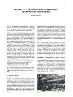
ABSTRACT
This paper describes the current development of the new
Wembley Stadium
Roof.
The final design has not yet
been completed at the time of writing, however the
principles of the scheme are established. Once
constructed, this roof will be one of the largest in the
world. The paper describes the background to the project
and the reasons behind the evolution of the current
scheme for this large area, long span
roof.
BACKGROUND
The New Wembley Stadium was conceived from the
sense that whilst the current stadium could boast a
glorious past it had little, if any future. As the
centrepiece of the 1924 British Empire Exhibition, it has
staged many celebrated football matches, since the
famous 1923 "White Horse" FA Cup Final. The most
notable football match ever staged however, was the
1966 World Cup Final. The stadium was also the venue
for the track and field events during the 1948 Olympics.
It has also become the traditional home of the Rugby
League Challenge Cup Final. By default therefore it has
become the National Stadium.
All agree that the current stadium has clearly passed the
point at which it can usefully continue to serve the as the
National Stadium. Faced with this position and the
prospect of a number of applications for major new
lottery funded stadia, Sport England established with the
Football Association, (FA) the Football League, The FA
Premier league, the Rugby Football Union and the
British Athletic Federation, a competition for the
development of a New National Stadium. In July 1995
bids were received with Wembley emerging as the
preferred location.
It was intended that the owners of the Stadium, Wembley
pic.
would take this forward with a body especially
established for the purpose, The English National
Stadium Trust. The Trust would lease the site from
Wembley pic and be responsible for the design,
construction and finance for the new stadium. This
arrangement ultimately could not be made to work, and
in the face of bids from private competitors such as
Arsenal FC, the lottery grant assigned to the project
would be used to purchase the existing stadium and it's
business. The finance would be raised by a development
company, Wembley National Stadium Ltd (WNSL) a
wholly owned subsidiary of the FA. This finance would
be secured on the basis that the FA would continue to
hold it's flagship events at the new stadium. After
negotiations with Wembley pic the existing Stadium and
business was purchased on 15 March 1999.
THE NEW STADIUM
The configuration of the new Stadium was primarily
^developed through the brief complied for the
competition, and expanded to suit the requirements for
expected use. The new Stadium is to be capable of
hosting events similar to that of the existing. Together
with the primary sporting events of football and rugby,
major athletics events were to be capable of being held.
Recent national publicity on the topic of athletics at
Wembley has shown this to be a very emotive subject,
one that thankfully is not for this paper. Other events that
complete the portfolio are concerts, pageants and
exhibitions.
The brief called for a "world class" Stadium which
would continue to uphold the traditions of the existing
Stadium. A full "bowl" arrangement for the terracing is
utilised as the whole of the stadium was being
reconstructed. This provides the opportunity to ensure
all the are spectators are wrapped around the action
creating an intimate environment, full of atmosphere.
With this arrangement, the Wembley "Roar" would
continue! A spectator capacity of 90,000 was eventually
chosen. During the development of the business case for
the operation of the stadium a 200 bed hotel, interactive
museum, 100,000 ft2 of offices a
5,000
seat (the largest
in London) banqueting suite and full spectator hospitality
and corporate facilities are to be provided.
These facilities could not all be fitted into the concourse
areas under the spectator bowl structure and are housed
mainly on the North side of the building, facing Olympic
Way. The roof of the Stadium is designed to cover in one
sweep the both the spectators and the other facilities
housed in the building. This has resulted in a very large
roof,
one of the largest in the world, containing long clear
internal spans.
242
The roof of a stadium is a very highly visible structure
and which dominates all views of the building, both
internally and externally. It therefore demands special
consideration from the design team. The existing
stadium's roof boasted the "Twin Towers". This very
emotive and powerful, national icon was the subject of
much debate. To keep the Towers or not? It was not a
viable option to retain the Towers in their original
positions. The new Stadium needed to be moved to the
North to create a piazza around the whole of the building.
It is possible to relocate the Towers, however it was felt
that a new image should be provided for the Stadium.
The roof for the new Stadium was the subject of a very
intense and detailed option study. It was necessary to
provide a column free space within the spectator bowl
and to cover the additional facilities housed in the North
of the building. The brief required all the spectators to be
covered. There was not however a requirement to have a
completely retractable
roof,
as the primary sporting
events for the Stadium had to be held in the open air.
However, could the capability for a closing roof be
excluded and the roof not "future proofed"? It would be
very difficult and prohibitively expensive to try and retro
fit a fully closing roof once the Stadium was constructed.
Future proofing is discussed later in this paper.
The configuration of the spectator bowl adopted with it's
much shorter sight distances and a roof covering all the
spectators also generates problems of shadow lines on
the pitch and lack of air movement over the playing
surface. Both of the above cause problems with grass
growth. Healthy grass needs both direct sunlight and
fresh air.
The current Stadium configuration with it's low set back
roof,
running track between the spectators and the pitch,
and the shallow seating tiers allows easy air movement
over the pitch. Even at 4.45pm in mid May (FA Cup
final) there is only a small portion of the pitch covering
the South Western corner flag in shadow. Apart from
pitch health, this is very important to the television
companies as their cameras cannot cope very easily with
moving in and out of shadow. Given this existing
condition it is imperative that the new configuration
gives a similar performance for both pitch health and
shadow lines. The solution for the roof needs to be able
to address these issues satisfactorily.
SCHEME DEVELOPMENT
The starting position for the scheme was that there
should be no columns in the spectator bowl. The
perimeter of the roof therefore needed to be supported at
the high back edge of the bowl. The saddle shape of the
bowl edge reflects the capacity requirements together
with maintaining the required standards for the pitch and
scoreboard sightlines. The edge of the roof will be
supported on the perimeter truss. This element of
structure is formed from the extension of the bowl
primary raking beams triangulated with V props to form
a continuous perimeter truss on which the roof edge
elegantly rests.
It was immediately apparent that the North side of the
building would be the dominant area and would need to
contain the major supporting elements of the
roof.
The
roof structure could then align primarily North South. If
a line of support could be gained at the internal leading
edge of the North
Roof,
main trusses could be utilised to
span from this edge to the Southern edge of the bowl.
Further advantages to the overall solution could be
gained by following this concept. As discussed, the
problems of shadow lines and air movement over the
pitch needed to be addressed. These problems could be
largely eliminated if the roof along the Southern side of
the Stadium could be retracted back to allow sunlight
onto the pitch. They could be closed before or during a
match if the weather deteriorated. The main North South
trusses could support retractable roof panels running
along the truss top chord. The requirement to cover all
spectators would still be achievable, albeit only during
inclement weather.
Fig 1 Schematic Section
243
To enable this option
to
work,
a
major supporting
element needed
to be
introduced which could provide
support
to the
internal leading edge
of
the North roof
and
could
be
supported outside
the
footprint
of the
building,
ensuring still
a
column free spectator bowl.
The
initial
public scheme utilised
4
masts
at the
front (North)
of the
stadium with twinned forestay cables attached
to
internal
edge
of the roof.
Twin backspans cables were anchored
back
to
foundation blocks
to the
North
of the
masts.
This scheme worked well
as a
structure, however
it was
felt that
the
intrusion
of the
masts directly
in
front
of the
building, together with their cables,
and the
same mast
type solution with other similar structures would
not be
special
or
unique enough
for the new
National Stadium.
Subsequently,
a
solution that found favour with
all was
produced. This utilised
a
massive arch, which
was
positioned over
the
Northern roof
and
spanned
the
whole
building East
to
West. This solution provided
an
efficient
and elegant solution
to
both problems
of
roof support
whilst giving
the
necessary icon
to the
Stadium.
A series
of
forestay cables
is
attached
to the
arch
supporting
the
internal leading edge
of
the Northern
roof,
and backstay cables anchor
to the
edge
of the
bowl,
neatly eliminating
all the
externally anchored cables
of
the mast solution. Refer
to
Figure
1.
The arch quickly became
the
accepted image
of the new
Stadium, replacing
the
existing Twin Towers
as the
icon
for
the new
National Stadium.
Once basic agreement
on the
arch solution
was
reached
working models
of
the Stadium were constructed, Figure
2.
A
full wind tunnel test model
was
prepared tested
to
confirm existing design data, determine accurate wind
loads
and
highlight
and
quantify
any
special effects
on
the roof
and
arch
for
this configuration.
THE ARCH
The arch takes
the
form
of a 7m dia. 138m
high,
315m
span open "basket weave" unclad lattice structure.
It is
formed
of 457 dia CHS
longitudinal chords with
diaphragms
at
approximately
20m
centres. Alternate
diaphragms
are
primary
and
support
the
stays. Steel
grades
are
S355
JO or J2 to BS EN
10025. Rolled
Hollow Sections S355
J2H to BS EN
10210. Protection
is
400 dft
micron epxoy primer
/
buildcoat
and a
75dft
micron finish coat, over
a
blast clean surface
to Sa 2.5 of
BS 7079, giving
the
period
to
first maintenance
of 30
years.
Access
to the
arch will need
to be
undertaken
for the
following reasons:
• Structural Inspection
• Lighting maintenance
/
replacement
• Repainting
(30
year interval)
• Festivity
/
celebration
(eg
pyrotechnics)
• Dressing
the
arch with flags
or
banners.
It
is
anticipated that maintenance will
be
through
the
centre
of the
arch.
For the
more thorough maintenance
tasks
a pre
fabricated platform that
is
launched from
the
North Roof would
be
winched
up
under
the
section
requiring attention, providing
a
safe working platform
for
the
maintenance crew.
The position
of
the arch
and it's
inclination have been
the
subject
of an
intensive iterative analysis process. This
to
try
and
ensure that under
all
load combinations
the
arch
acts
as far as
possible
in it's
most efficient state, direct
compression.
The treatment
of the
springing points
of the
arch will
be
important
as it is
expected that these points will
be
used
by
the
visiting spectators
as
favourite spots
for
Fig
2
Architectural Model
244
photographs. In the design of the knuckle springing
points, there is also the security and safety issues to be
considered from people potentially being able to scale
the arch. Figure 3 below.
Fig 3 Arch Support Detail
The stays are spiral strand galvanised wires grade 1570.
Cables. Cable interior and exterior corrosion protected.
First inspection within 5 years of initial coating and a
major inspection after 15 years from initial coating.
Touch up will be required at the time of the initial
inspection, with complete re coating a likely option at the
time of the major inspection. Under the approved'
maintenance regime the cables have a guaranteed life of
60 years.
Generally the forestays cables range between 110m and
135 mm dia. The backstays between 55 and 95 mm dia.
There are 8 support points provided along the North roof
leading edge. The first 2 supports at the East and West
ends are primary picking up the main North South T3
and T4 trusses. These trusses span to the South edge of
the bowl and are the main elements which support the
whole of the Southern roof area.
THE ROOF PLATE
The roof plate main structure runs North South. Refer to
figure 4 for the member references. The surface is
profiled to fall from the North South centreline away to
the East and West. The roofing material is to be a
mixture of standing seam aluminium (eg Kalzip) and
30%
translucent polycarbonate sheeting (eg Lexan). The
polycarbonate sheeting is introduced to allow diffused
light through the roof towards the leading edges. This
provides a light gradient of open to fully solid roof which
improves hard shadow lines.
Soffit treatment (lining) will be provided in certain areas
to hide walkways and services. This lining will also have
acoustic benefits during concerts. Further to this there
will also be areas treated with specific acoustic lining
panels to both absorb sound and modify the general
acoustic properties of the spectator bowl.
350 mm cold rolled nested purlins at 3m centres running
East West, support the roofing spanning between the
main roof trusses. The centre 10 bays are at 13.5m
reducing to 10.5m for the end 6 bays.
On the North
roof,
the primary fink type trusses are 6m
deep spanning up to 75m. These are supported from the
arch stays and the Northern edge of the bowl. The top
chord is a box section generally 750 x 500 mm deep with
a cable bottom chords and CHS V struts at third points.
A longitudinal truss Til is provided to support the
alternate secondary North South trusses and to provide in
plane rigidity to the roof plate when considering
assymetric and dynamic loading.
The main T3 and T4 trusses span to the Southern edge of
the bowl. T3 spans 155m and T4 129m. These trusses,
together with the edge T5 trusses support the main
Southern roof and carry the rails for the moving roof
panels. Lateral stability of these main trusses is provided
by a series of horizontal cable ties.
At the leading edge of the Southern roof truss T13 is
located. This spans 135 m between the T3 trusses to
support the central section of the Southern
roof.
As the
truss is curved in plan, diagonal cable ties are introduced
back into the roof plate to counteract the bottom chord
kick out.
The main North South 6 m deep fink trusses are utilised
as runway beams for the sliding roof panels. Fabricated
box sections top chords are provided, as in the North
roof.
Refer to Figure 5 for a complete isometric view of
the roof structure.
SLIDING ROOF
In order to meet the requirement to provide maximum
covered seating whilst still allowing daylight for pitch health
a moving roof over the whole of the Southern side of the
stadium is required. The roof panels are nested over the
static section of the roof and at each end double stacked The
permanent roof structure running North South provides the
runway beams supporting the track for the panels.
The area of roof that moves is split into 5 bays, one middle
section extending the length of the pitch (135m between
trusses T3), and two bays at each end, covering the end
stands. These panels are supported of the T3,4 and 5 trusses.
The end bay panels are subdivided to allow them to double
stack on top of the fixed roof without projecting over the
Southern edge of the building.
245
ARCH OVER
ARCH OVER
Fig 4 Roof Plan
During operation, in order to maintain a positive wheel
friction to the rails, it is proposed that a wind speed limit
of 20 m/s (approximately 50 mph) is imposed. This is in
line with common practice at other operable roof stadia.
This limitation to operation pertains to operational
reasons only. The panels themselves are designed to
withstand the design wind loading at any location, fully
closed, part open or fully open.
The panels are generally framed by fabricated box
sections (up to 3m deep for the central large cantilever
panel) which are connected to the running bogies.
Secondary framing UB sections are utilised with full
diagonal rod bracing for each panel to ensure racking of
the panel does not occur. A full cycle for the roof to open
or close will take 20 minutes.
FUTURE PROOFING
Whilst there is no current requirement for a fully closing
roof for the Stadium, there may be, in the future cause to
want this facility. The existing design is able to be
adapted to cater for this by the strengthening of certain
key elements.
the T3 trusses. To cope with this additional load the T3
trusses, the supporting arch stays, the arch and the arch
foundations would all need to be strengthened.
It is considered that if this strengthening was not carried
out at the time of construction, any retro fit would be
virtually impossible and expensive to carry out. The
technical problems could be overcome however any
future fully independent structure over the top of the roof
would be visually intrusive and would be unlikely to gain
planning permission. This would effectively deny the
retro fit route for this option.
SUMMARY
The
roof,
especially the arch of the New National
Stadium provides the icon that will take over from the
Twin Towers and continue the tradition of Wembley for
the next 50 years. The stadium will be a truly
magnificent stage for the major events that will be held
there. It will elevate England into a country capable of
hosting almost any international sporting event in style.
As the kingpin for bids for the World Cup, and the
Olympic Games it is considered that any such bid would
be very strong built around the New Wembley Stadium.
The fully closing roof would take the form of two
additional central overlapping panels clear spanning the
length of the pitch (135m). These would be supported on
Fig 5 Roof Isometric
NOTE
The structural engineering for the New National Stadium
is being undertaken by the Mott Stadium Consortium.*
This consortium is lead by Mott MacDonald and contains
Connell Wagner Pty, Modus Consulting Engineers and
Weidlinger Associates Inc.
REFERENCES
1 Wembley National Stadium, House of Commons -
Culture, Media and Sport - Fourth Report
2 March 2000
2 The New English National Stadium, World Stadium
Team February 2000
3
Key Development Criteria, Technical Development
Criteria, English National Stadium Development
Company Limited March 1999
247
KEEPING THE DOORS OPEN:
THE OLYMPIC STADIUM, SYDNEY
S Morley
Principal
Modus Sinclair Knight Merz
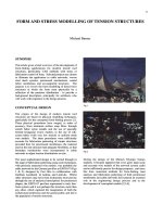
Fig 1 Aerial view of Stadium Australia
Sports facilities, where shelter is provided, invariably fall
into the category of widespan enclosures. Stadia and
arenas tie up vast amounts of a client's capital and the
planet's resources and therefore should be designed to be
suitable for many uses as far as practicable. This may
mean providing a range of environments through altering
their widespan enclosures.
Where field sports played on natural turf form some of
those uses the enclosure needs to be open centred to
promote grass growth and comply with current
regulations for 'outdoor' sports. Having the ability to
close this central opening can greatly increase the
possible uses and also provides event surety at least in
the face of a temperamental climate.
It is, to a degree, possible to quantify the benefits of this
flexibility of extent of enclosure by assessing the revenue
from additional usage and avoidance of lost revenue
from cancelled events (although the latter is difficult to
assess as past events at other facilities statistically
represent such a small sample of total available event
248
days that little guidance can be drawn from "I've never
known an event cancelled in thirty years"). However,
this judgement will necessarily be made based on current
knowledge of the forthcoming developments in the event
markets in which the new facility is intended to compete
and the only certain thing about such markets is that they
change, often unpredictably. Hence it can be of benefit
to provide for flexibility of enclosure or at least for
adaptability to be able to introduce such flexibility at a
later date.
Two of Australia's most recent multipurpose sports and
entertainment facilities - Stadium Australia at the
Olympic site in Homebush Sydney, and Colonial
Stadium, Docklands, Melbourne, are good examples of
the application of this strategy. Stadium Australia, the
host venue for the 2000 Olympics, is designed to operate
in two distinct modes. In Olympic mode the North and
South sections of the bowl are unroofed to allow space
for large temporary grandstands, each accommodating
15,000 people.
After the Olympics these end tiers are due to be removed
an the perimeter enclosure completed with the addition
of North and South Roofs. At the same time the lower
tier of seating will be moved inwards by nearly 16m on
the sides and 20m on the ends to greatly improve their
proximity to field sports. This strategy was part of an
innovative financial package which helped secure the
project for the Multiplex led team in a B.O.O.T (build,
own, operate and transfer) competition. Under the
auspices of such a procurement method the development
team was acutely aware of the need for long term
financial viability. Whilst, based on 'current'
understanding of how the stadium might be used, there as
insufficient justification for providing the flexibility of
full as well as partial enclosure, it was considered
important to 'keep this door open' by allowing
adaptability for this flexibility in the future.
The roof of Stadium Australia follows , and in fact was
borne out of the geometry of the seating bowl. In the
longer term post Olympic mode, from the lowest point
on the end stands to the highest point on the side stands
there was a height differential of perhaps 40 metres and
the natural shape to fit this saddle perimeter was the
hyperbolic paraboloid. With this geometry the roof over
the side stands curves gently downward maximising
weather protection for every dollar spent on the roof
whilst hugging the higher sightlines. There was also
potentially a construction advantage in that this iconic
doubly curved form is generated from two sets of straight
lines parallel to but progressively rotated from two
principal generators at 45 degrees to the main axes of the
stadium. Structurally such a surface can be very
materially efficient as loads can be transferred by in
plane or membrane forces.
However this geometric and structural purity is rudely
interrupted by the roof plan form in Olympic mode when
just crescents of roof over the side stands are required. In
plane action across the stadium is not possible in this
Fig 2 Architectural Image of the Stadium with End Roofs in Place
mode and instead the surface would have to act primarily
in bending to some form of edge stiffening along the
front edge of each crescent. Nonetheless the other
advantages of the hyperbolic parabaloid remained and it
was decided to pursue this geometry. True to this
surface, the front edge of the crescents were parabolic
which suggested a form of arch as edge stiffening. Once
provided the arch stiffening would attract a large
proportion of the load in both Olympic and post Olympic
modes and to increase the efficiency of this system still
further the main arch was lifted above the HP surface by
up to 12 meters at its apex.
The concentrated lateral load components generated by
arch forms are best taken directly to foundations on a
continuation of the line of thrust (curve of the arch).
However, the arch line had to remain above the HP
surface to the edge of the roofed area which left it more
than 20 metres above precinct level. There was simply
not enough site area to continue on this line and therefore
some form of cantilever thrust block was required.
Interestingly a degree of mitigation was provided by
allowing the arch line to change in response to areas of
concentrated gravity loads. Because of the geometry of
the opening such a concentration occurs where the roof
ends meet the arch (here there was also a requirement to
support 50 tonne video screens) and the arch line was
therefore deliberately diverted inward and downward at
the ends like the profile of a crab. This lowered the thrust
blocks slightly such that the arches could spring from a
point 17 metres above the precinct.
The resulting roof geometry therefore was the hyberbolic
paraboloid surface curtailed to a vertical cylinder
defining the back of the seating and with two crabbed
arches stiffening the edges of the central rectangular
opening in post Olympic mode and providing full edge
support in Olympic mode.
Early on in the development of this design the client
instructed the designers (Architect Bligh Lobb Sports
Architect and Engineers Modus with Sinclair Knight
Merz) to consider how a fully closing roof could be
provided and what steps might sensibly need to be taken
Fig 4 Architectural Image of fully roofed arena
now to ensure this remained a possibility for the future.
It was found that geometrically the hyberbolic parabaloid
could readily accommodate a fully closing
roof.
The
arched edge reinforcement running East West provided
natural trackways for a simple sliding system albeit on a
constant radius curved track. Furthermore, the fact that
the top surface of the end roofs dishes down following
the HP surface between these trackways provided
additional space for the depth needed for the moving roof
panels to clear span the 100 metres plus between the
rails.
This property was particularly useful as it proved
necessary to stack a pair of moving leaves above arch
and fixed roof within the curtilage of the stadium.
Inclusion of a closing roof would therefore increase loads
on the arches and their supporting thrust blocks and
foundations requiring commensurate strengthening.
Also as this additional loading is to one side of the arch
centreline, the roof diagrid supported off the arch which
restrains the arch horizontally also would require
strengthening locally. The design work instructed
allowed informed decisions to be taken on which aspect
of their strengthening could and should be carried out
during initial construction to 'keep the door open' whilst
minimising the amount of capital tied up in steel and
concrete for a potentially lengthy period before any
revenue is gained from this benefit. The strategy for
Fig 5 End segment of arch truss
Fig 6 Computer model of west stand
strengthening the arches was to add a new central
compression element within the arch trusses. This could
conceivably be carried out at a later stage by unloading
the arches using the same temporary towers employed
for their construction and feeding in the new
compression member in pieces small enough for
assembly by site welding (used extensively for initial
construction of the arches).
However, strengthening of the arch supports would be
altogether more involved to the point of being
impractical. Fortunately it was found that the cost of
strengthening the pins at the ends of the arches, the pin
plates,
thrust blocks and foundations was reasonable and
therefore these measures were included in the initial
development. Also it was found that the diagrid
strengthening local to the arches could be achieved
simply and with minimal cost by deepening the diagrid
in this region.
By this means the option of installing the future closing
roof has been kept open in a logical way and with the
minimum of additional expenditure and construction
beforehand.
With Colonial Stadium, in Melbourne's Docklands, the
decision was taken that the roof should be closeable,
subject to the additional costs involved being supported
by the business plan. Thereby a stadium designed as an
open stadium complete with an AFL sized natural turf
pitch could become fully enclosed to operate as a
multipurpose venue to attract a greater number or events.
Although having a moderate seating capacity of 52,000,
the infield is exceptionally large by European or US
standards, to accommodate the AFL pitch and closing the
1.7 hectare retractable roof creates an enclosed arena of
vast proportions.
Several forms of retractions were explored and a simple
sliding mechanism with two 50 x 165 m span doors
selected for cost efficiency and design efficiency. Such
an arrangement naturally concentrates loads on two
distinct lines at the ends of the doors and recognising this
the Architectural team of Daryl Jackson Architects Pty
Ltd and Bligh Lobb Sports Architects, proposed that the
upper tier be divided into quadrants allowing four corner
supports to be 'pulled in' under these loads.
This arrangement could readily be accommodated as the
moderate capacity compared with the long infield
perimeter meant seats would be redistributed without
detriment to viewing quality or efficiency.
The Engineering Team of Connell Wagner with Modus
used this opportunity to the full to produce a very
efficient structure which, even with the 165m span doors
Fig 7 Colonial Stadium main roof support arch
and supporting tracks weighed less than 100kg/m2
overall. In detail the doors comprise shallow I sections
suspended off pairs of asymmetric tied arch prismatic
trusses. This asymmetry was borne out of a desire to
minimise shadows on the pitch and to reduce the visual
impact of the roof by chamfering the volume of the inner
truss to the pitch side and outer truss to the precinct side
respectively. By making the I section roof beams
deliberately flexible the doors are better able to
accommodate differential movements and slopes of their
supporting tracks. The tracks themselves comprise 4m
deep prismatic trusses which are carried over the 120m
span between corner supports again by tied arch trusses
with chamfers to the pitch side. Great care was taken in
developing active positioning systems both of the door
relative to the tracks, to control racking of the bogie sets
relative to the door trusses, to minimise the forces
induced in the structure should racking occur. This was
particularly important here as racking forces would have
the benefit of a 165 metre lever with which to annoy the
fixed supporting structure.
Constructors, Bauderstone Hornibrook have now
completed the stadium and it is hoped its flexibility of
enclosure will contribute to the long term success of the
venue.
In conclusion, the sports and entertainment market
appears increasingly competitive. In this market it can
be an advantage to have flexibility of enclosure or at least
the ability to add this flexibility later. Both approaches
can be integrated into Structural and Architectural
designs seamlessly if included into the design scope early
enough.