Using the Renesas Graphics API to Create a User Interface_Part2_LabProcedure
Bạn đang xem bản rút gọn của tài liệu. Xem và tải ngay bản đầy đủ của tài liệu tại đây (791.99 KB, 10 trang )
LAB PROCEDURE
Using the Reneas Graphics API to create a user interface V1.0 Page 1 of 10
Graphics Lab: Using the Renesas Graphics API to
Create a User Interface – Part 2
RX TFT-LCD Solution
Description: This objective of this lab session is to introduce you the Renesas Graphics API
(GAPI) and associated application framework. We will start with an introduction to frame based
graphics and basic GAPI calls, than move to more advanced GAPI calls and framework details,
and finally an example of a user interface screen design process. Starting with concept artwork,
we will work through the components required to create a user interface, discusses details
about behavior, and illustrate how the embedded graphics are generated. Finally, we will
implement the user interface on a low-cost embedded system platform.
Lab Sections
3 Create Graphical Resource Files 2
4
Create New Screen 5
5
Creating Interaction with the Screen 9
Lab Objectives
1. Learn a method to create GUI graphics
2. Use GAPI and application framework on an
embedded platform to create a user
interface.
3. Understand callback function interaction.
Skill Level
1. Familiarity with the HEW IDE and debuggers
Time to Complete Lab
160 Minutes
Lab Materials
Please verify you have the following materials at
your lab station.
• HEW v4
• RX Standard Toolchain v1.2
• E1 debugger
• Inkscape and ImageMagick software
•
RX62N based Serious SIM205
LAB PROCEDURE
Using the Reneas Graphics API to create a user interface V1.0 Page 2 of 10
3 Create Graphical Resource Files
Overview:
In this lab we’re going to extract components from an SVG (Scalable Vector Graphics) file and make
component BMP (bitmap) files that are compatible with GAPI.
Procedural Steps
Step 3.1 Open the “Medical.svg” file in the
“C:\Workspace\5L08I_Graphics_API\Lab3_Graphical_Resources” directory by double clicking it.
This file will open in “Inkscape” (an open source SVG editor).
Press “5” to center and display the image.
Step 3.2 To help “clear our plate”, delete all text by selecting and pressing “delete”.
Text will be inserted at runtime by the application code.
Unlike many programs, to select multiple items in Inkscape, hold down
the “shift” key while selecting.
To make selection easier, you can view the SVG in “outline mode”.
Enter outline mode by “<alt>-V, D, O”. Exit outline by “<alt>-V,D,N”
LAB PROCEDURE
Using the Reneas Graphics API to create a user interface V1.0 Page 3 of 10
Step 3.3 Looking at the image in outline mode, we can see there are duplications of some
components…so let’s delete them so we don’t have to consider them separately.
Step 3.4
We are now going to export each of the individual components as separate “bitmap” files to
facilitate converting them to BMP files for GAPI usage.
- To create these component “bitmap” files:
1. Select all objects except for the background image and the slider bar (overlapping images
are a problem for the export operation). You should have eight objects selected (slider bar and
slider button are separate objects).
2. Open the export dialog by pressing <ctrl-shift-E>
You can “drag” a box to select multiple items. Only items completely
within the box will be selected.
LAB PROCEDURE
Using the Reneas Graphics API to create a user interface V1.0 Page 4 of 10
.
Check “batch export…” and “hide all ” boxes, and press export.
3. Now, select just the background image and export, select just the slider bar and export.
Ensure that “Hide all except selected” is checked in each case.
4. Inkscape has exported these component images as “.png” files into
the “C:\Workspace\5L08I_Graphics_API\Lab3_Graphical_Resources” directory. You can use
Windows Explorer to view these files in a thumbnail view.
Step 3.5
5. At this point, we are done with Inkscape and you can close it <alt-F4> (there is no reason
to save the modified SVG file).
Renesas GAPI does not handle “.png” files, so we need to convert these exported files to a
format that can be properly used by GAPI. To do this, we will use an open source tool called
“ImageMagick”.
Run the “ConvertMed.bat” file located in
the
Step 3.6
“C:\Workspace\5L08I_Graphics_API\Lab3_Graphical_Resources” by double clicking on it
from Windows Explorer.
Examine the command lines being used to convert the files into GAPI compatible images. We
will discuss these in some detail after the lab. You can use Windows Explorer to view these
generated files in a thumbnail view.
Step 3.7
To create the fonts that will be used by our screen, we will use the GAPI font generation tool.
1. Open Windows Explorer and navigate to the
“C:\Workspace\5L08I_Graphics_API\Lab3_Graphical_Resources” directory.
2. Run the “CreateFont.bat” by double clicking.
3. Note how the batch file invokes the font generator 4 times creating 4 font files rendered at 14,
18, 24 and 42 pixels (the 24 and 42 pixel font are rendered bold).
4. Close the command window by pressing any key.
5. In Windows Explorer, you will see the four newly created “.efnt” font files.
PLEASE WAIT. WE WILL CONTINUE AS A GROUP.
Lab 3 Questions:
1. What are several advantages and disadvantages to building the screen
at runtime from components (as opposed to pre-rendering the
information into the bitmaps)?
LAB PROCEDURE
Using the Reneas Graphics API to create a user interface V1.0 Page 5 of 10
4 Create New Screen
Overview:
In this lab section, we will place our new objects on the screen, and ensure their appearance meets our
needs. Because of time constraints, we have provided a basic screen file that we will examine and
enhance.
Procedural Steps
Step 4.1 Open the HEW workspace “DirectLCD.hws” in the “Lab4_Create_Screen” directory by double-
clicking the file from within Windows Explorer.
C:\Workspace\5L08I_Graphics_API\Lab4_Create_Screen\DirectLCD.hws
Step 4.2
Step 4.3
SIM205 hardware should be assembled, connected to power, switched on and the E1 should
be plugged into the PC. The connection dialog should automatically launch (if not, please
initiate by pressing “<alt-D>,N”). Select “OK” on the dialogs until connected.
Step 4.4
Ensure the code has been built by pressing “F7”
Step 4.5
Download the “DirectLCD.abs” module by double-clicking in workspace panel or by pressing
“<alt-D>,W,A”.
Now download the resources.bin file that was generated as part of the build process by running
a script from the debug console by pressing the “play” button on it.
This process will also start the application running. You should see the “resource load” screen
on the LCD panel, followed by the “home” screen.
Step 4.6
By pressing the “Medical Icon” button on the display we will enter our “screen”. Note that
currently only the background image is shown. Stop the program by pressing “<alt-D>,H”.
Open the “ScreenMed.c” file (should be open in tab on main window, if not double-click the file
in the Workspace pane). You can also navigate the following by selecting the navigation tab in
LAB PROCEDURE
Using the Reneas Graphics API to create a user interface V1.0 Page 6 of 10
the Workspace pane (ensure “group by file” is selected).
Step 4.7
Locate the constructor function (by searching using <ctrl-H> or by using the navigation pane).
This function is registered with the framework (via the “ScreenMedicalData” structure) to be
called to initially build the screen. Here you can see the “FileFind” framework call to locate the
“Med_BG” bitmap file and pass it to the “R_expand_jpeg” API function to display the image at
the 0,0 screen location.
You can also see the call the framework “BasicConstructor”. This call will process all screen
objects within the “Icons” table (also registered within the “ScreenMedicalData” structure).
Currently there are no screen objects in this table (hence nothing on the screen).
Constructor Function
static void Constructor(Screen_t const *pS)
{
/* Clear the background */
{
/* LAB1_10: expand a jpeg file */
uint8_t const *pJPG = FileFind(pResources, "Med_BG");
int32_t width = R_BMP_Width(backFrameBuf);
int32_t height = R_BMP_Height(backFrameBuf);
R_init_jpeg();
R_expand_jpeg(pJPG,
FileSizeFind(pResources, "Med_BG"),
(uint16_t *)(((uint8_t *)backFrameBuf) + R_BMP_Offset(backFrameBuf))+(width*(height-1)), -width);
}
// Run default behavior
BasicConstructor(pS);
}
Step 4.8
/* MUST INCLUDE NULL TERMINATED RECORD */
Locate the Icons table by pressing <ctrl-F> and searching for “Icons”. Note that currently we
have much of the initialization excluded by “#if 0”. Change the 0 to a 1 to allow the code to
build (you can try running the code by pressing <F7> to build and <shift-F5> to run to see what
our screen currently looks like.
static const ScreenObj_t Icons[]=
{
/* Bit map Address Color Scheme Function call X Pos Y Pos */
#if 0
{ &pBMP_HomeIcon, T_HomeButtonScheme, ButtonBack, 418, 236 },
{ &pBMP_ButtonS, T_CalendarScheme, TimerRTC_Display, 10, 240 },
…
{ &pBMP_Mode, T_ButtonScheme, MedModePress, 278, 130 },
{ &pBMP_StartStop, T_ButtonScheme, MedStartStopPress, 344, 130 },
{ &pBMP_ONOFF, T_ButtonScheme, MedONOFFPress, 410, 130 },
{ &pBMP_Status, T_StatusScheme, MedStatus, 278, 176 },
#endif
{ NULL, NULL, NULL, 0, 0 },
};
LAB PROCEDURE
Using the Reneas Graphics API to create a user interface V1.0 Page 7 of 10
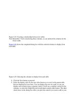
Step 4.9
Use the following diagram to note the relationship between the “Icons” table and our screen
objects (dimensions are pixels).
Touch the buttons and slider, note their behavior.
Note that the “Run/Stop” button definition is incomplete, we will address that next.
Step 4.10
Step 4.11
The objects are being displayed because they are being called by the framework (via the Icons
table registered callback functions).
Scroll down through the screen callback functions within “ScreenMed.c”.
Note the calls to the framework handlers “ButtonHandler”, ”SliderHandler”, and
“DataBoxHandler”.
These handlers are just conveniences that eliminate recreation of common behavior for some
generic objects.
static int16_t state=0;
Locate the “MedStartStopPress” callback function. Note the code that is currently conditionally
excluded. Using the framework calls “FileFind” and “ButtonHandler” greatly simplify the code
necessary to insert this object on the screen.
/* locate the BMP resources */
if (NULL == pBMP_StartStop)
{
pBMP_StartStop= FileFind(pResources, "MedButton");
}
if(0 != (state = ButtonHandler(pS, pMsg, (uint8_t *)StateText[MedState], state)))
{
if (ME_PRESS == pMsg->event)
{
MedState = (0 == MedState)? 1: 0;
}
}
LAB PROCEDURE
Using the Reneas Graphics API to create a user interface V1.0 Page 8 of 10
Step 4.12
Step 4.13
Include the code for the start/stop button by changing to “#if 1”. Test by building <F7> and
running <shift-F5>.
Step 4.14
Stop the program by pressing “<alt-D>,H”.
When you have completed this lab section, please close HEW by pressing <alt-F4>.
Step 4.15
PLEASE WAIT. WE WILL CONTINUE AS A GROUP.
Lab 4 Questions:
1. Where in the source code are the six “data boxes” being handled?
2. What would be another candidate for a “handler” looking at the source
in this example?
LAB PROCEDURE
Using the Reneas Graphics API to create a user interface V1.0 Page 9 of 10
5 Creating Interaction with the Screen
Overview:
In this lab section we’re going to add some interaction to our callback functions. In this section, hints are
available at the end of the “ScreenRefrig.c” file that can be referenced as necessary.
Procedural Steps
Step 5.1 Open the HEW workspace “DirectLCD.hws” in the “Lab5_Interaction” directory by double-
clicking the file from within Windows Explorer.
C:\Workspace\5L08I_Graphics_API\Lab5_Interaction\DirectLCD.hws
Step 5.2
Step 5.3
SIM205 hardware should be assembled, connected to power, switched on and the E1 should
be plugged into the PC. The connection dialog should automatically launch (if not, please
initiate by pressing “<alt-D>,N”). Select “OK” on the dialogs until connected.
Step 5.4
Ensure the code has been built by pressing “F7”
Step 5.5
Download the “DirectLCD.abs” module by double-clicking in workspace panel or by pressing
“<alt-D>,W,A”. Run the project by pressing “<shift>F5”, this is the state we left it in lab 4.
Step 5.6
To add some interaction, we are going to simulate data values for the graph and data boxes in
a separate thread. Additionally, we are going to request updates to several of the objects on a
periodic basis via another thread.
Rather than creating RTOS threads that will only be used in a single screen, the framework has
allocated several threads that can be shared by multiple screens (activated when necessary).
Within the constructor function of the “ScreenMed.c” file, change “#if 0” to “#if 1”.
Test by building <F7> and running <shift-F5>.
Step 5.7
Examine the “genData” (simulated data) and “genEvents” functions (periodic event generation).
The “MedInc” array in “genData” is controlling the amount that each data variable is
incremented per time tick, the “heartbeat” array contains the simulated data for the graph.
The “EventValues” array in “genEvents” contains the values used to signal the screen objects
that they should update.
Step 5.8
Press and hold the slider (note the graph waveform), hold and move the slider.
Press the “Run” button (note slider behavior)
Press the “Mode” and “Power” Buttons and note the behavior.
In the “MedStatus” callback function, change the “FileFind” name argument "
Step 5.9
MedStatusBox" to
"StatusBox"
Test by building <F7> and running <shift-F5>.
Using the code in the “genData” function as a template, control LED 2 based on the state of the
“Power Button”. Hint, this code can be done in the MedONOFFPress Callback or the “genData”
// Run default behavior
BasicConstructor(pS);
#if 0
(void)ScreenTaskStart(genData);
(void)ScreenTaskStart(genEvents);
#endif
LAB PROCEDURE
Using the Reneas Graphics API to create a user interface V1.0 Page 10 of 10
function based on the “GraphState” variable.
Test by building <F7> and running <shift-F5>.
Step 5.10
Step 5.11
Stop the program by pressing “<alt-D>,H”.
When you have completed this lab section, please close HEW by pressing <alt-F4>.
Step 5.12
PLEASE WAIT. WE WILL CONTINUE AS A GROUP.
Lab 5 Questions:
1. What happens if you use the FileFind framework call to search for a
resource and it is not located?