báo cáo MIPS PIPELINED CPU
Bạn đang xem bản rút gọn của tài liệu. Xem và tải ngay bản đầy đủ của tài liệu tại đây (675.06 KB, 72 trang )
MIPS PIPELINED CPU
SVTH : Nhóm 14
1
1. Yêu cầu:
- Thiết kế chip Mips Pipeline 32bit dựa trên thiết kế và tập lệnh của chip
Mips Single-Cycle đã thực hiện ở lab3.
2. Giới thiệu về chip pipelined:
- Khác với chip Single-cycle khi các lệnh đều được thực hiện xong trong
1 chu kỳ máy, chip pipelined chia một câu lệnh ra thành 5 bước (steps):
+ Đọc lệnh từ bộ nhớ (Instruction Fetch – IF)
+ Giải mã lệnh và đọc các thanh ghi (Instruction Decode – ID)
+ Tính toán kết quả của câu lệnh hoặc địa chỉ (Execution –EX)
+ Đọc hoặc ghi dữ liệu trên bộ nhớ dữ liệu (Memory access – MEM)
+ Ghi kết quả vào thanh ghi (Write back – WB)
- Câu lệnh sau không cần đợi câu lệnh trước hoàn tất mới bắt đầu thực
hiện mà mỗi step sẽ được thực hiện liên tiếp, do đó cải thiện đáng kể về tốc độ
thực hiện các chương trình
3. Thiết kế:
2
3.1. Sơ đồ khối tổng quát:
3.2. Các bước thực hiện 1 câu lệnh:
3
*Có 5 bước với các chức năng riêng:
+ Đọc lệnh từ bộ nhớ (Instruction Fetch – IF)
Sử dụng địa chỉ lưu trong thanh ghi PC để giải mã ra mã máy của câu
lệnh tiếp theo và lưu vào thanh ghi trung gian IF/ID.
Giá trị PC được cộng thêm 4 và lưu vào thanh ghi trung gian IF/ID.
+ Giải mã lệnh và đọc các thanh ghi (Instruction Decode – ID)
Sử dụng mã máy của câu lệnh lưu trong thanh ghi IF/ID làm đầu vào cho
khối Regfile.
Khối Control sử dụng phần opcode của mã máy của câu lệnh để giải mã
thành các tín hiệu điều khiển, ngoài tín hiệu SignEx được sử dụng cho khối mở
rộng, các tín hiệu khác được lưu vào thanh ghi trung gian ID/EX.
- Đọc các thanh ghi Rs, Rt từ bộ thanh ghi và lưu vào thanh ghi trung
gian ID/EX.
- Khối mở rộng sử dụng tín hiệu SignEx từ khối Control để mở rộng dấu
hay mở rộng zero của 16 bit thấp của mã máy thành 32 bit và lưu vào thanh ghi
ID/EX.
- Địa chỉ của các thanh ghi Rs, Rt, Rd được lưu vào thanh ghi ID/EX.
+ Tính toán kết quả của câu lệnh hoặc địa chỉ (Execution –EX)
- Khối ALU sử dụng các đầu vào đã được lưu trong thanh ghi ID/EX để
tính toán và lưu kết quả vào thanh ghi trung gian EX/MEM.
- Một bộ mux được dùng để lựa chọn thanh ghi đích từ 2 thanh ghi Rt, Rd
và lưu địa chỉ vào thanh ghi EX/MEM.
4
- Địa chỉ mới của PC sau câu lệnh BNE cũng được tính toán trong khối
này. Một số bộ mux được dùng để lựa chọn giá trị mới cho PC từ các câu lệnh
rẽ nhanh BNE, J, JR.
- Các tín hiệu điều khiển MemWrite, MemtoReg và RegWrite được lưu
tiếp vào thanh ghi EX/MEM.
+ Đọc hoặc ghi dữ liệu trên bộ nhớ dữ liệu (Memory access – MEM)
- Sử dụng kết quả tính toán từ khối ALU và tín hiệu điều khiển
MemWrite từ thanh ghi EX/MEM để thực hiện đọc hoặc ghi vào bộ nhớ dữ
liệu. Kết quả đọc ra được ghi vào thanh ghi trung gian MEM/WB.
- Các giá trị đầu ra của ALU, địa chỉ thanh ghi đích cùng với 2 tín hiệu
điều khiển MemtoReg và RegWrite được ghi lại vào thanh ghi MEM/WB.
+ Ghi kết quả vào thanh ghi (Write back – WB)
- Sử dụng tín hiệu MemtoReg từ thanh ghi MEM/WB để lựa chọn dữ liệu
cần ghi vào thanh ghi.
- Sử dụng địa chỉ thanh ghi đích và tín hiệu cho phép ghi RegWrite để
thực hiện công việc ghi dữ liệu vào bộ thanh ghi.
5
3.3. Thiết kế các thanh ghi pipelind:
- Ta sử dụng các thanh ghi pipeline làm trung gian lưu kết quả thực hiện
của mỗi khối trong mỗi chu kỳ để làm đầu vào cho các khối sau trong chu kỳ
tiếp theo
- Có 4 thanh ghi pipelined nằm giữa các khối :
+ Thanh ghi IF/ID :
Để lưu các giá trị PC+4 và mã máy của câu lệnh .
+ Thanh ghi ID/EX :
Để lưu các giá trị, PC + 4, địa chỉ của lệnh Jump, 2 giá trị đọc ra từ bộ
thanh ghi.
Giá trị mở rộng 32bits từ 16bits.
Địa chỉ các thanh ghi Rs, Rt, Rd.
Các tín hiệu điều khiển từ khối Control: ALUOp, ALUSrc, RegDst,
Branch, Jump, MemWrite, RegWrite, MemtoReg.
6
+ Thanh ghi EX/MEM :
Để lưu các giá trị : Kết quả tính toán của khối ALU, giá trị dùng để ghi
vào bộ nhớ file thanh ghi, địa chỉ của thanh ghi đích. Các tín hiệu điều khiển:
MemWrite, RegWrite, MemtoReg.
+ Thanh ghi MEM/WB :
Để lưu các giá trị: Giá trị đọc ra từ bộ nhớ dữ liệu, kết quả của khối ALU,
địa chỉ thanh ghi đích
3.3. Một số xung đột trong cấu trúc Pipelined
a. Stuctural hazard:
- Là xung đột xảy ra khi phần cứng không hỗ trợ việc kết hợp xử lý các
lệnh đồng thời.
b. Data hazard:
- Xảy ra khi mà dữ liệu cần cho lệnh tiếp theo chưa có sẵn vì đang được
xử lý ở các lệnh trước đó.
7
c. Control hazard:
- Là xung đột xảy ra khi có lệnh rẽ nhánh
- Khi một lệnh rẽ nhánh được thực thi thì chưa biết được địa chỉ lệnh tiếp theo
3.4. Cách xử lý Hazard
a. Structural hazard:
- Thêm các thanh ghi giữa các tiến trình để chứa dữ liệu được xử lý từ các tiến
trình trước.
- Các thanh ghi sẽ chia phần cứng thành những phần tương ứng với các Stage
b. Data hazard:
Có 2 kĩ thuật xử lý data hazard:
- Forwarding
- Stalling
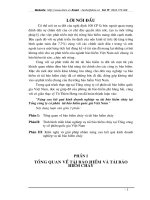
* Kĩ thuật forwarding:
- Là kĩ thuật chuyển tiếp dữ liệu đầu ra sau khi tính toán từ bộ ALU hoặc sau
khi truy cập bộ nhớ dữ liệu vào sử dụng ở lệnh sau đó, không chờ đến khi ghi
vào file thanh ghi
8
Datapath
Điều kiện xảy ra Forwarding :
• EX\MEM.RegsRd=ID\EX.RegsRs
• EX\MEM.RegsRd=ID\EX.RegsRt
• MEM\WB.RegsRd= ID\EX.RegsRs
• MEM\WB.RegsRd= ID\EX.RegsRt
Bảng giá trị các tín hiệu điều khiển
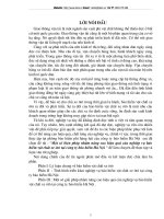
*Kỹ thuật stalling
- Là kĩ thuật trì hoãn việc thực thi 1 lệnh để chờ dữ liệu có được từ các câu lệnh
trước
9
Datapath
Điều kiện xảy ra Stalling: Toán hạng nguồn của 1 lệnh được lấy từ lệnh
lw đứng sát trước nó. Lúc này chưa thể forwarding được, phải trì hoãn 1 chu kì.
• ID/EX.MemRead=1
• IF/ID.RegsRs=ID/EX.RegsRd
• IF/ID.RegsRt=ID/EX.RegsRd
10
c. Control Hazard
Là xung đột xảy ra khi có lệnh rẽ nhánh
Khi một lệnh rẽ nhánh được thực thi thì chưa biết được địa chỉ lệnh tiếp theo
Cách xử lý :
Thực thi các lệnh bình thường. Nếu xảy ra rẽ nhánh thì flush các lệnh vừa tìm,
giải mã ở sau.
- Xây dựng 1 khối có thể flush các lệnh đã tìm và giải mã ở tiến trình IF và ID.
- Điều kiện flush: 1 trong những điều kiện:
+ khi thực thi lệnh Jump, JR
+ lệnh BNE thỏa điều kiện nhảy
4. Thiết kế datapath cho MIPS Pipelined CPU
4.1. Khối InstructionMem
Dùng để lưu trữ lệnh dưới dạng mã máy (nhị phân).
Kích thước mỗi lệnh khi dịch ra mã máy là 32 bits, tốn 32 bits để lưu trữ.
Đầu vào bộ nhớ lệnh là địa chỉ lệnh cần lấy, đầu ra là mã máy của câu
lệnh tương ứng lấy được
module InstructionMem (address,instruction);
input [31:0]address;
output [31:0]instruction;
reg [31:0]instrmem[25:0];
reg [31:0] temp;
buf #150 buf0(instruction[0],temp[0]),
buf1(instruction[1],temp[1]),
buf2(instruction[2],temp[2]),
11
buf3(instruction[3],temp[3]),
buf4(instruction[4],temp[4]),
buf5(instruction[5],temp[5]),
buf6(instruction[6],temp[6]),
buf7(instruction[7],temp[7]),
buf8(instruction[8],temp[8]),
buf9(instruction[9],temp[9]),
buf10(instruction[10],temp[10]),
buf11(instruction[11],temp[11]),
buf12(instruction[12],temp[12]),
buf13(instruction[13],temp[13]),
buf14(instruction[14],temp[14]),
buf15(instruction[15],temp[15]),
buf16(instruction[16],temp[16]),
buf17(instruction[17],temp[17]),
buf18(instruction[18],temp[18]),
buf19(instruction[19],temp[19]),
buf20(instruction[20],temp[20]),
buf21(instruction[21],temp[21]),
buf22(instruction[22],temp[22]),
buf23(instruction[23],temp[23]),
buf24(instruction[24],temp[24]),
buf25(instruction[25],temp[25]),
buf26(instruction[26],temp[26]),
12
buf27(instruction[27],temp[27]),
buf28(instruction[28],temp[28]),
buf29(instruction[29],temp[29]),
buf30(instruction[30],temp[30]),
buf31(instruction[31],temp[31]);
always @(address)
begin
temp=instrmem[address/4];
end
initial
begin
$readmemh("instr.dat", instrmem);
end
endmodule
4.2 Khối thanh ghi lệnh PC
Là thanh ghi chứa địa chỉ của lệnh sắp được thực thi.
Vì địa chỉ lệnh có 32 bits nên PC là thanh ghi 32 bits.
Xây dựng thanh ghi này tương tự xây dựng thanh ghi trong LAB 1 đã
làm, nguyên tắc vẫn dùng DFF.
module PC_Block(DataIN, DataOUT,PCWrite, clk, Reset);
input clk;
13
input Reset;
input PCWrite;
input [31:0] DataIN;
output [31:0] DataOUT;
reg [31:0] DataOUT;
always @(negedge clk or negedge Reset)
begin
if( Reset == 1)
DataOUT <= 0;
else
begin
if(PCWrite == 1'b1)
begin
DataOUT <= DataIN;
end
else
begin
DataOUT <= DataOUT;
end
end
end
14
4.3 Bộ cộng Add
Vì thông thường sau mỗi chu kì xung clock, MIPS CPU cần thực thi lệnh
tiếp theo, do đó địa chỉ lệnh cần tăng lên , tức giá trị của thanh ghi PC
tăng lên.
Vì cấu trúc bộ nhớ lệnh, nên sau mỗi chu kì clock PC tăng lên 4.
module Add(Add_In1,Add_In2,out_Add);
input [31:0] Add_In1;
input [31:0] Add_In2;
output [31:0] out_Add;
wire [31:0] Cout;
add_bit bit0(Add_In1[0],Add_In2[0], 1'b0, out_Add[0], Cout[0]) ;
add_bit bit1(Add_In1[1],Add_In2[1], Cout[0], out_Add[1], Cout[1]);
add_bit bit2(Add_In1[2],Add_In2[2], Cout[1], out_Add[2], Cout[2]);
add_bit bit3(Add_In1[3],Add_In2[3], Cout[2], out_Add[3], Cout[3]);
add_bit bit4(Add_In1[4],Add_In2[4], Cout[3], out_Add[4], Cout[4]);
add_bit bit5(Add_In1[5],Add_In2[5], Cout[4], out_Add[5], Cout[5]);
add_bit bit6(Add_In1[6],Add_In2[6], Cout[5], out_Add[6], Cout[6]);
add_bit bit7(Add_In1[7],Add_In2[7], Cout[6], out_Add[7], Cout[7]);
add_bit bit8(Add_In1[8],Add_In2[8], Cout[7], out_Add[8], Cout[8]);
add_bit bit9(Add_In1[9],Add_In2[9], Cout[8], out_Add[9], Cout[9]);
add_bit bit10(Add_In1[10],Add_In2[10], Cout[9], out_Add[10], Cout[10]);
add_bit bit11(Add_In1[11],Add_In2[11], Cout[10], out_Add[11], Cout[11]);
add_bit bit12(Add_In1[12],Add_In2[12], Cout[11], out_Add[12], Cout[12]);
add_bit bit13(Add_In1[13],Add_In2[13], Cout[12], out_Add[13], Cout[13]);
15
add_bit bit14(Add_In1[14],Add_In2[14], Cout[13], out_Add[14], Cout[14]);
add_bit bit15(Add_In1[15],Add_In2[15], Cout[14], out_Add[15], Cout[15]);
add_bit bit16(Add_In1[16],Add_In2[16], Cout[15], out_Add[16], Cout[16]);
add_bit bit17(Add_In1[17],Add_In2[17], Cout[16], out_Add[17], Cout[17]);
add_bit bit18(Add_In1[18],Add_In2[17], Cout[17], out_Add[18], Cout[18]);
add_bit bit19(Add_In1[19],Add_In2[19], Cout[18], out_Add[19], Cout[19]);
add_bit bit20(Add_In1[20],Add_In2[20], Cout[19], out_Add[20], Cout[20]);
add_bit bit21(Add_In1[21],Add_In2[21], Cout[20], out_Add[21], Cout[21]);
add_bit bit22(Add_In1[22],Add_In2[22], Cout[21], out_Add[22], Cout[22]);
add_bit bit23(Add_In1[23],Add_In2[23], Cout[22], out_Add[23], Cout[23]);
add_bit bit24(Add_In1[24],Add_In2[24], Cout[23], out_Add[24], Cout[24]);
add_bit bit25(Add_In1[25],Add_In2[25], Cout[24], out_Add[25], Cout[25]);
add_bit bit26(Add_In1[26],Add_In2[26], Cout[25], out_Add[26], Cout[26]);
add_bit bit27(Add_In1[27],Add_In2[27], Cout[26], out_Add[27], Cout[27]);
add_bit bit28(Add_In1[28],Add_In2[28], Cout[27], out_Add[28], Cout[28]);
add_bit bit29(Add_In1[29],Add_In2[29], Cout[28], out_Add[29], Cout[29]);
add_bit bit30(Add_In1[30],Add_In2[30], Cout[29], out_Add[30], Cout[30]);
add_bit bit31(Add_In1[31],Add_In2[31], Cout[30], out_Add[31], Cout[31]);
endmodule
module add_bit(r1,r2,cin,outbit,cout);
input r1,r2,cin;
output cout,outbit;
wire c1,c2,c3;
xor #(50) or1(outbit,r1,r2,cin);
16
and #(50) and1(c1,r1,r2);
and #(50) and2(c2,r2,cin);
and #(50) and3(c3,r1,cin);
or #(50) or2(cout,c1,c2,c3);
endmodule
4.3 Khối DataMem
module datamem(read_data, address_data, writedata, readenable,writeenable,
clk);
input [31:0] address_data, writedata;
input writeenable, readenable, clk;
output [31:0] read_data;
reg [7:0] datamemory[1023:0];
reg [31:0] temp;
buf #100 buf0(read_data[0],temp[0]),
buf1(read_data[1],temp[1]),
buf2(read_data[2],temp[2]),
buf3(read_data[3],temp[3]),
buf4(read_data[4],temp[4]),
buf5(read_data[5],temp[5]),
buf6(read_data[6],temp[6]),
buf7(read_data[7],temp[7]),
buf8(read_data[8],temp[8]),
17
buf9(read_data[9],temp[9]),
buf10(read_data[10],temp[10]),
buf11(read_data[11],temp[11]),
buf12(read_data[12],temp[12]),
buf13(read_data[13],temp[13]),
buf14(read_data[14],temp[14]),
buf15(read_data[15],temp[15]),
buf16(read_data[16],temp[16]),
buf17(read_data[17],temp[17]),
buf18(read_data[18],temp[18]),
buf19(read_data[19],temp[19]),
buf20(read_data[20],temp[20]),
buf21(read_data[21],temp[21]),
buf22(read_data[22],temp[22]),
buf23(read_data[23],temp[23]),
buf24(read_data[24],temp[24]),
buf25(read_data[25],temp[25]),
buf26(read_data[26],temp[26]),
buf27(read_data[27],temp[27]),
buf28(read_data[28],temp[28]),
buf29(read_data[29],temp[29]),
buf30(read_data[30],temp[30]),
buf31(read_data[31],temp[31]);
18
// if writeenable
always @(posedge clk)
if (writeenable)
begin
datamemory[address_data]=writedata[31:24];
datamemory[address_data+1]=writedata[23:16];
datamemory[address_data+2]=writedata[15:8];
datamemory[address_data+3]=writedata[7:0];
end
// if readenable
always @(address_data or datamemory[address_data] or
datamemory[address_data+1] or datamemory[address_data+2] or
datamemory[address_data+3])
if (readenable)
begin
temp={datamemory[address_data],datamemory[address_data+1],datamemory[a
ddress_data+2],datamemory[address_data+3]};
end
initial
begin
$readmemh("data.dat", datamemory);
19
end
endmodule
4.5. Khối file thanh ghi
module regfile(ReadData1,ReadData2,WriteData,ReadRegister1,
ReadRegister2,WriteRegister,RegWrite,clk,reset);
input [4:0]ReadRegister1,ReadRegister2,WriteRegister;
input [31:0] WriteData;
input RegWrite, clk,reset;
output [31:0] ReadData1, ReadData2;
wire [31:0] W0,W1,W2,W3,W4,W5,W6,W7,W8,W9,W10,
W11,W12,W13,W14,W15,W16,W17,W18,W19,W20,
W21,W22,W23,W24,W25,W26,W27,W28,W29,W30,W31;
wire [31:0] GroupOfBit[0:31];
wire [31:0] WriteEnable;
// Decoder Block
Decoder Decoder1(RegWrite, WriteRegister, WriteEnable);
// 32 Register Blocks
Register Reg0 ({1'b1}, {32'b0}, W0, clk,reset);
Register Reg1 (WriteEnable[1 ], WriteData, W1, clk,reset);
Register Reg2 (WriteEnable[2 ], WriteData, W2, clk,reset);
Register Reg3 (WriteEnable[3 ], WriteData, W3, clk,reset);
Register Reg4 (WriteEnable[4 ], WriteData, W4, clk,reset);
Register Reg5 (WriteEnable[5 ], WriteData, W5, clk,reset);
Register Reg6 (WriteEnable[6 ], WriteData, W6, clk,reset);
20
Register Reg7 (WriteEnable[7 ], WriteData, W7, clk,reset);
Register Reg8 (WriteEnable[8 ], WriteData, W8, clk,reset);
Register Reg9 (WriteEnable[9 ], WriteData, W9, clk,reset);
Register Reg10(WriteEnable[10], WriteData, W10, clk,reset);
Register Reg11(WriteEnable[11], WriteData, W11, clk,reset);
Register Reg12(WriteEnable[12], WriteData, W12, clk,reset);
Register Reg13(WriteEnable[13], WriteData, W13, clk,reset);
Register Reg14(WriteEnable[14], WriteData, W14, clk,reset);
Register Reg15(WriteEnable[15], WriteData, W15, clk,reset);
Register Reg16(WriteEnable[16], WriteData, W16, clk,reset);
Register Reg17(WriteEnable[17], WriteData, W17, clk,reset);
Register Reg18(WriteEnable[18], WriteData, W18, clk,reset);
Register Reg19(WriteEnable[19], WriteData, W19, clk,reset);
Register Reg20(WriteEnable[20], WriteData, W20, clk,reset);
Register Reg21(WriteEnable[21], WriteData, W21, clk,reset);
Register Reg22(WriteEnable[22], WriteData, W22, clk,reset);
Register Reg23(WriteEnable[23], WriteData, W23, clk,reset);
Register Reg24(WriteEnable[24], WriteData, W24, clk,reset);
Register Reg25(WriteEnable[25], WriteData, W25, clk,reset);
Register Reg26(WriteEnable[26], WriteData, W26, clk,reset);
Register Reg27(WriteEnable[27], WriteData, W27, clk,reset);
Register Reg28(WriteEnable[28], WriteData, W28, clk,reset);
Register Reg29(WriteEnable[29], WriteData, W29, clk,reset);
Register Reg30(WriteEnable[30], WriteData, W30, clk,reset);
21
Register Reg31(WriteEnable[31], WriteData, W31, clk,reset);
// 32x32to32 Multiplexor1 Block
multiplexor32x32to32 Multi1(W0, W1, W2,W3, W4,W5,W6,W7,W8,W9,
W10, W11, W12, W13, W14, W15, W16,W17,W18, W19,
W20, W21, W22, W23, W24, W25, W26, W27, W28,
W29, W30,W31, ReadRegister1, ReadData1);
// 32x32to32 Multiplexor2 Block
multiplexor32x32to32 Multi2(W0, W1, W2,W3, W4,W5,W6,W7,W8,W9,
W10, W11, W12, W13, W14, W15, W16,W17,W18, W19,
W20, W21, W22, W23, W24, W25, W26, W27, W28,
W29, W30,W31, ReadRegister2, ReadData2);
endmodule
`timescale 1 ps / 100 fs
module Decoder(RegWrite, WriteRegister, WriteEnable);
input RegWrite;
input [4:0] WriteRegister;
output [31:0] WriteEnable;
DEC5_32 a(WriteEnable[31:0],WriteRegister[4:0],RegWrite);
22
endmodule
module Dec2(Q,A,EN);
input [1:0]A;
input EN;
output [3:0]Q;
wire [1:0]AN;
not #(50)n[1:0](AN,A);
and #(50)(Q[3],A[1],A[0],EN);
and #(50)(Q[2],A[1],AN[0],EN);
and #(50)(Q[1],AN[1],A[0],EN);
and #(50)(Q[0],AN[1],AN[0],EN);
endmodule
//mach giai ma 3->8
module Dec3(Q,A,S);
input [2:0]A;
input S;
output [7:0]Q;
wire [2:0]AN;
not #(50)n[2:0](AN,A);
and #(50)(Q[7],A[2],A[1],A[0],S);
and #(50)(Q[6],A[2],A[1],AN[0],S);
and #(50)(Q[5],A[2],AN[1],A[0],S);
23
and #(50)(Q[4],A[2],AN[1],AN[0],S);
and #(50)(Q[3],AN[2],A[1],A[0],S);
and #(50)(Q[2],AN[2],A[1],AN[0],S);
and #(50)(Q[1],AN[2],AN[1],A[0],S);
and #(50)(Q[0],AN[2],AN[1],AN[0],S);
endmodule
module DEC5_32(Q,A,EN);
input [4:0]A;
input EN;
output [31:0]Q;
wire [3:0]S;
Dec2 d(S,A[4:3],EN);
Dec3 d1(Q[31:24],A[2:0],S[3]);
Dec3 d2(Q[23:16],A[2:0],S[2]);
Dec3 d3(Q[15:8],A[2:0],S[1]);
Dec3 d4(Q[7:0],A[2:0],S[0]);
endmodule
module D_FF (q, d, reset, clk,enable);
output q;
input d, reset, clk,enable;
reg q;
24
wire clock;
and #50 and0(clock,clk,enable);
// Indicate that q is stateholding
always @(posedge clock or posedge reset)
if (reset)
q = 0; // On reset, set to 0
else
q = d; // Otherwise out = d endmodule
endmodule
`timescale 1 ps / 100 fs
module Multiplexor32to1(GroupOfBit, ReadRegister, ReadData);
input [31:0] GroupOfBit;
input [4:0] ReadRegister;
output ReadData;
wire [7:0]t;
MUX4 m1(t[7],ReadRegister
[1:0],GroupOfBit[31],GroupOfBit[30],GroupOfBit[29],GroupOfBit[28]);
MUX4 m2(t[6],ReadRegister
[1:0],GroupOfBit[27],GroupOfBit[26],GroupOfBit[25],GroupOfBit[24]);
MUX4 m3(t[5],ReadRegister
[1:0],GroupOfBit[23],GroupOfBit[22],GroupOfBit[21],GroupOfBit[20]);
MUX4 m4(t[4],ReadRegister
[1:0],GroupOfBit[19],GroupOfBit[18],GroupOfBit[17],GroupOfBit[16]);
25