3 Level Measurement
Bạn đang xem bản rút gọn của tài liệu. Xem và tải ngay bản đầy đủ của tài liệu tại đây (776.79 KB, 10 trang )
1
Ha Noi, March 2012
1
MEASUREMENT TECHNOLOGY
LEVEL MEASUREMENT
BUI Dang Thanh, NGUYEN Thi Lan Huong
School of Electrical Engineering, Hanoi University of Science and Technology
1 Dai Co Viet road, Hà Nôi, Viêt Nam
Ha Noi, March 2012
2
Presentation outline
1. Introduction
Discrete-Level Detectors
Continuous-Level Detectors
2. Measurements Using the Effects of Density
3. Time-of-Flight Measurements
4. Level Measurements by Detecting Physical Properties
Introduction
What is level ?
is defined as the filling height of a liquid
or bulk material, for example, in a tank or
reservoir.
They have two classifications: discrete
and continuous.
Discrete-level detectors can only detect
whether the material is at a certain level.
The continuous-level detector provides an
analog signal that is proportional to the
material level.
3
Ha Noi, March 2012
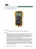
Introduction
Representation of a tank with
a liquid or solid material
(hatched area), the product to
be measured.
The level sensor can be
mounted (a) contacting product
at the bottom, (b) as a
contactless instrument on top,
(c) as an intrusive sensor, or
(d) at the sides as a level
switch.
4
Ha Noi, March 2012
2
Discrete-Level Detectors
Discrete-level detectors determine when a liquid has reached
a certain level.
An application of this type would be determining when to stop
the fill cycle of a washing machine.
Ha Noi, March 2012
5
Continuous-Level Detectors
Continuous-level
detectors provide
a signal that is
proportional to the
material level.
Ha Noi, March 2012
6
Ha Noi, March 2012
7
Measurements Using the Effects of Density
1. Displacer
2. Float
3. Pressure Gages
4. Balance Method *
Displacer
Ha Noi, March 2012
8
3
Displacer
Displacers measure the
buoyancy of a solid body that
is partially submerged in the
liquid. The change in weight is
measured.
Quantities of a solid body
immersed into a liquid. The
forces F can be calculated
from Equations 2, 3, and 4. r =
density; b = length of the
body; Ld = dipped length.
Ha Noi, March 2012
9
Displacer
The cross section A of the body is assumed to be constant
over its length b . The weight of force F G due to gravity g
and mass m is:
The buoyant force F B accounts for the partial length L d
that is submerged with the remainder of the body in the
atmosphere:
Ha Noi, March 2012
10
Displacer
Ha Noi, March 2012
11
Combining 2 Equations in previous slide gives the resulting
force to be measured by an appropriate method:
The result for level Ld, related to the lower edge of the
displacer is:
Displacer
Ha Noi, March 2012
12
Level, interface and
density sensor using the
effects of buoyancy.
And the surrounding
density pL can be
calculated:
4
Float
Ha Noi, March 2012
13
Float
Floats are similar to displacers, but are swimming on the
liquid’s surface due to the buoyancy. Hence, the density of
the float must be lower than the density of the liquid.
Ha Noi, March 2012
14
Float
If the float is very flat, it is called a “sensing
plate”. This plate is mechanically guided, e.g.,
by a servo control, on the surface until uplift
is detected. For solids, specially shaped
perpendicular floats are helpful.
Ha Noi, March 2012
15
Pressure Gages
Ha Noi, March 2012
16
5
Pressure Gages
A hydrostatic pressure p , caused by the weight of the
product, is present at the bottom of a tank, in addition to the
atmospheric pressure p0 :
Pressure gages at the bottom of the tank measure this
pressure. In process tanks with varying atmospheric
pressure, a differential pressure measurement is achieved by
measuring the difference between the pressure at the
bottom and that at the top of the tank, above the liquid.
Ha Noi, March 2012
17
Pressure Gages
Level gaging by hydrostatic pressure measurement. The
bottom pressure p is proportional to level.
Ha Noi, March 2012
18
Pressure Gages
• Figure (b) in previous slide shows a vertical arrangement
with three sensors; the measurements of p1 and p2 are used
to compensate for the influence of density pL, and to
calculate the level:
Ha Noi, March 2012
19
Time-of-Flight Measurements
Ha Noi, March 2012
20
1. Ultrasonic
2. Microwaves
3. Laser/Light *
6
Basic Principle
Although different types of physical waves (acoustic or
electromagnetic) are applied, the principle of all these
methods is the same: a modulated signal is emitted as a wave
toward the product, reflected at its surface and received by
a sensor, which in many cases is the same, (e.g., the ultrasonic
piezoelectric transducer or the radar antenna). Figure in next
slide demonstrates the principle of operation. The measuring
system evaluates the time-of-flight t of the signal:
Where v is the propagation velocity of the waves.
Ha Noi, March 2012
21
Basic Principle
Ha Noi, March 2012
22
•
(a) Representation of time-of-
flight measurements. The emitter
couples a wave (ultrasonic or
electromagnetic) into the
atmosphere that propagates the
wave toward the liquid. Its surface
reflects the wave and a sensor
receives it.
•
(b) Due to the propagation velocity
v, a time delay is measured
between emission and receipt of
the signal. This example is
characterized by a modulated
burst. The time scale is arbitrary.
One can generate an unmodulated pulse, a modulated burst as
in Figure 11.6(b), or special forms. Table 11.1 lists the main
properties of the three preferred types of waves, used for
time-of-flight level gaging.
The very short time spans of only a few nanoseconds for
radar and laser measurement techniques require the use of
time expansion by sampling or special evaluation methods
Basic Principle
Ha Noi, March 2012
23
Ha Noi, March 2012
24
Ultrasonic
7
Ultrasonic
Ultrasonic waves are longitudinal acoustic waves with
frequencies above 20 kHz. Ultrasonic waves need a
propagation medium, which for level measurements is the
atmosphere above the product being measured.
Sound propagates with a velocity of about 340 m s–1 in air;
but this value is highly dependent on temperature and
composition of the gas, and also on its pressure. In vacuum,
ultrasonic waves cannot propagate.*
Piezoelectric transducers are utilized as emitter and
detector for ultrasonic waves, a membrane coupling it to the
atmosphere.
The sensor is installed as in Figure slide22(b), the signal form
is as in Figure slide22(b). Level gaging is, in principle, also
possible with audible sound 16 Hz to 20 kHz or infrasonic
waves less than 16 Hz.
Ha Noi, March 2012
25
Ultrasonic
Another procedure is to propagate the waves
within the liquid by a sensor mounted at the
bottom of the tank.
The velocity of sound in the liquid must be known,
considering the dependence on temperature and
type of liquid.
This method is similar to an echo sounder on ships
for measuring the water depth. For more
information about time-of-flight ultrasound
evaluation techniques, refer to *
Ha Noi, March 2012
26
Ha Noi, March 2012
27
Microwaves
Microwaves
Microwaves are generally understood to be electromagnetic
waves with frequencies above 2 GHz and wavelengths of
less than 15 cm. For technical purposes, microwave
frequencies are used up to max. 120 GHz; in practice, the
range around 10 GHz (X-band) is preferred.
The usually applied time-of-flight measurements with
microwaves are RADAR-based [8, 9]. The term “RADAR” is
generally understood to mean a method by means of which
short electromagnetic waves are used to detect distant
objects and determine their location and movement. It is an
acronym from RAdio Detection And Ranging
Ha Noi, March 2012
28
8
Microwaves
Ha Noi, March 2012
29
Microwaves
Ha Noi, March 2012
30
FIGURE 11.8 Design of a compact industrial level radar system. The converter above the
flange includes the complete microwave circuitry, signal processing stages, microprocessor
control, display, power supply, and output signal [6].
Microwaves
For level measuring systems, a small radiation angle is
desirable in order to avoid interfering reflections from the
tank wall or tank internals as much as possible. The larger
the aperture area, the smaller the radiation angle and the
higher the antenna gain. The power balance is given by the
general radar equation:
Ha Noi, March 2012
31
Microwaves
The reflection factor R of the product’s surface is
dependent on the dielectric permittivity ε
r
of the liquid or
bulk material:
In level measurement situations, the reflecting area is so
large that it intersects the beam cross section completely;
therefore, D2 is approximately proportional with distance
d2. Thus also, the received power decreases
proportionately with d2, as derived in [8]:
Ha Noi, March 2012
32
9
Microwaves
This is not the case if the waves propagate within an
electromagnetic waveguide, like a vertical tube dipping into
the liquid, called a stilling well. Here, the propagation is
nearly without losses.
An alternative method using electromagnetic waves is to
propagate them in a cable. Next Figure illustrates the
operation with a cable dipped into the liquid or bulk material.
Where the dielectric permittivity of the surrounding medium
changes, part of the wave is reflected. This method can be
applied to interface measurements too.
Ha Noi, March 2012
33
Microwaves
Ha Noi, March 2012
34
Principle of
operation of a wire-
conducting high-
frequency level
measurement
system.
Level Measurements by Detecting Physical
Properties
Ha Noi, March 2012
35
1. Ultrasonic
2. Microwaves
3. Laser/Light *
Basic method
Electrical Properties
• The sensor must be in direct or indirect contact with the
product to detect its electrical properties. For continuous
measurement, only part of the intrusive sensor must be in
contact with the product to detect the difference in
dielectric permittivity or conductivity.
Capacitive
• In most applications, a rod electrode is arranged vertically in
the tank. The electrode can be (1) noninsulated if the liquid is
nonconductive, or (2) insulated. The metallic vessel acts as a
reference electrode.
Ha Noi, March 2012
36
10
Basic method
Ha Noi, March 2012
37
References
1.
2.
3.
4.
5. Moderm control techonlogy – components &
system
38
Ha Noi, March 2012
Ha Noi, March 2012
39
Thank you for your attention!