Bài giải đề thi Olympic Vật lý quốc tế 2012
Bạn đang xem bản rút gọn của tài liệu. Xem và tải ngay bản đầy đủ của tài liệu tại đây (347.28 KB, 10 trang )
Problem T1. Focus on sketches (13 points)
Part A. Ballistics (4.5 points)
i. (0.8 pts) When the stone is thrown vertically upwards, it
can reach the point x = 0, z = v
2
0
/2g (as it follows from the
energy conservation law). Comparing this with the inequality
z ≤ z
0
− kx
2
we conclude that
z
0
= v
2
0
/2g. [0.3 pts]
Let us consider the asymptotics z → −∞; the trajectory of
the stone is a parabola, and at this limit, the horizontal dis-
placement (for the given z) is very sensitive with respect to the
curvature of the parabola: the flatter the parabola, the larger
the displacement. The parabola has the flattest shape when
the stone is thrown horizontally, x = v
0
t and z = −gt
2
/2, i.e.
its trajectory is given by z = −gx
2
/2v
2
0
. Now, let us recall
that z ≤ z
0
− kx
2
, i.e. −gx
2
/2v
2
0
≤ z
0
− kx
2
⇒ k ≤ g/2v
2
0
.
Note that k < g/2v
2
0
would imply that there is a gap between
the parabolic region z ≤ z
0
− kx
2
and the given tra jectory
z = −gx
2
/2v
2
0
. This trajectory is supposed to be optimal for
hitting targets far below (z → −∞), so there should be no such
a gap, and hence, we can exclude the option k < g/2v
2
0
. This
leaves us with
k = g/2v
2
0
. [0.5 pts]
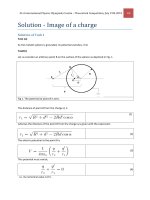
ii. (1.2 pts) Let us note that the
stone trajectory is reversible and due
to the energy conservation law, one
can equivalently ask, what is the min-
imal initial speed needed for a stone
to be thrown from the topmost point
of the spherical building down to the
ground without hitting the roof, and what is the respective tra-
jectory. It is easy to understand that the trajectory either needs
to touch the roof, or start horizontally from the topmost point
with the curvature radius equal to R. Indeed, if neither were
the case, it would be possible to keep the same throwing angle
and just reduce the speed a little bit — the stone would still
reach the ground without hitting the roof. Further, if it were
tangent at the topmost point, the trajectory wouldn’t touch
nor intersect the roof anywhere else, because the curvature of
the parabola has maximum at its topmost point. Then, it
would be possible to keep the initial speed constant, and in-
crease slightly the throwing angle (from horizontal to slightly
upwards): the new trajectory wouldn’t be neither tangent at
the top nor touch the roof at any other point; now we can re-
duce the initial speed as we argued previously. So we conclude
that the optimal tra jectory needs to touch the roof somewhere,
as shown in Fig.
iii. (2.5 pts) The brute force approach would be writing down
the condition that the optimal trajectory intersects with the
building at two points and touches at one. This would be de-
scribed by a fourth order algebraic equation and therefore, it is
not realistic to accomplish such a solution within a reasonable
time frame.
Note that the interior of the building needs to lie inside the
region where the targets can be hit with a stone thrown from
the top with initial speed v
min
. Indeed, if we can throw over
the building, we can hit anything inside by lowering the throw-
ing angle. On the other hand, the boundary of the targetable
region needs to touch the building. Indeed, if there were a
gap, it would be possible to hit a target just above the point
where the optimal trajectory touches the building; the traject-
ory through that target wouldn’t touch the building anywhere,
hence we arrive at a contradiction.
So, with v
0
corresponding to the optimal trajectory, the tar-
getable region touches the building; due to symmetry, overall
there are two touching points (for smaller speeds, there would
be four, and for larger speeds, there would b e none). With the
origin at the top of the building, the intersection points are
defined by the following system of equations:
x
2
+ z
2
+ 2zR = 0, z =
v
2
0
2g
−
gx
2
2v
2
0
.
Upon eliminating z, this becomes a biquadratic equation for x:
x
4
g
2v
2
0
2
+ x
2
1
2
−
gR
v
2
0
+
v
2
0
4g
+ R
v
2
0
g
= 0.
Hence the speed by which the real-valued solutions disappear
can be found from the condition that the discriminant vanishes:
1
2
−
gR
v
2
0
2
=
1
4
+
gR
v
2
0
=⇒
gR
v
2
0
= 2.
Bearing in mind that due to the energy conservation law, at
the ground level the squared speed is increased by 4gR. Thus
we finally obtain
v
min
=
v
2
0
+ 4gR = 3
gR
2
.
Part B. Mist (4 points)
i. (0.8 pts) In the plane’s reference frame, along the channel
between two streamlines the volume flux of air (volume flow
rate) is constant due to continuity. The volume flux is the
product of speed and channel’s cross-section area, which, due
to the two-dimensional geometry, is proportional to the channel
width and can be measured from the Fig. Due to the absence of
wind, the unperturbed air’s speed in the plane’s frame is just v
0
.
So, upon measuring the dimensions a = 10 mm and b = 13 mm
(see Fig), we can write v
0
a = ub and hence u = v
0
a
b
. Since at
point P , the streamlines are horizontal where all the velocities
are parallel, the vector addition is reduced to the scalar addi-
tion: the air’s ground speed v
P
= v
0
−u = v
0
(1 −
a
b
) = 23 m/s.
ii. (1.2 pts) Although the dynamic pressure
1
2
ρv
2
is relatively
small, it gives rise to some adiabatic expansion and compres-
sion. In expanding regions the temp er ature will drop and hence,
the pressure of saturated vapours will also drop. If the dew
point is reached, a stream of droplets will appear. This process
will start in a point where the adiabatic expansion is maximal,
i.e. where the hydrostatic pressure is minimal and consequently,
as it follows from the Bernoulli’s law p +
1
2
ρv
2
= const, the dy-
namic pressure is maximal: in the place where the air speed in
— page 1 of 5 —
wing’s frame is maximal and the streamline distance minimal.
Such a point Q is marked in Fig.
iii. (2 pts) First we need to calculate the dew point for the air
of given water content (since the relative pressure change will
be small, we can ignore the dependence of the dew point on
pressure). The water vapour pressure is p
w
= p
sa
r = 2.08 kPa.
The relative change of the pressure of the saturated vapour is
small, so we can linearize its temperature dependence:
p
sa
− p
w
T
a
− T
=
p
sb
− p
sa
T
b
− T
a
=⇒ T
a
− T = (T
b
− T
a
)
(1 −r)p
sa
p
sb
− p
sa
;
numerically T ≈ 291.5 K. Further we need to relate the air
speed to the temperature. To this end we need to use the en-
ergy conservation law. A convenient ready-to-use form of it is
provided by the Bernoulli’s law. Applying this law will give
a good approximation of the reality, but strictly speaking, it
needs to be modified to take into account the compressibility
of air and the associated expansion/contraction work. Con-
sider one mole of air, which has the mass µ and the volume
V = RT/p. Apparently the process is fast and the air par-
cels are large, so that heat transfer across the air parcels is
negligible. Additionally, the process is subsonic; all together
we can conclude that the process is adiabatic. Consider a seg-
ment of a tube formed by the streamlines. Let us denote the
physical quantities at its one end by index 1, and at the other
end — by index 2. Then, while one mole of gas flows into
the tube at one end, as much flows out at the other end. The
inflow carries in kinetic energy
1
2
µv
2
1
, and the outflow carries
out
1
2
µv
2
2
. The inflowing gas receives work due to the pushing
gas equal to p
1
V
1
= RT
1
, the outflowing gas performs work
p
2
V
2
= RT
2
. Let’s define molar heat capacities C
V
= µc
V
and
C
p
= µc
p
. The inflow carries in heat energy C
V
RT
1
, and the
outflow carries out C
V
RT
2
. All together, the energy balance
can be written as
1
2
µv
2
+ C
p
T = const. From this we can
easily express ∆
v
2
2
=
1
C
v
2
crit
(
a
2
c
2
− 1) = c
p
∆T , where c is the
streamline distance at the point Q, and further
v
crit
= c
2c
p
∆T
a
2
− c
2
≈ 23 m/s,
where we have used c ≈ 4.5 mm and ∆T = 1.5 K. Note that
in reality, the required speed is probably somewhat higher, be-
cause for a fast condensation, a considerable over-saturation is
needed. However, within an order of magnitude, this estimate
remains valid.
Part C. Magnetic straws (4.5 points)
i. (0.8 pts) Due to the superconduct-
ing walls, the magnetic field lines cannot
cross the walls, so the flux is constant
along the tube. For a closed contour in-
side the tube, there should be no circu-
lation of the magnetic field, hence the
field lines cannot be curved, and the field
needs to be homogeneous. The field lines
close from outside the tube, similarly to a solenoid.
ii. (1.2 pts) Let us consider the change of the magnetic energy
when the tube is stretched (virtually) by a small amount ∆l.
Note that the magnetic flux trough the tube is conserved: any
change of flux would imply a non-zero electromotive force
dΦ
dt
,
and for a zero resistivity, an infinite current. So, the induc-
tion B =
Φ
π r
2
. The energy density of the magnetic field is
B
2
2µ
0
.
Thus, the change of the magnetic energy is calculated as
∆W =
B
2
2µ
0
πr
2
∆l =
Φ
2
2µ
0
πr
2
∆l.
This energy increase is achieved owing to the work done by the
stretching force, ∆W = T ∆l. Hence, the force
T =
Φ
2
2µ
0
πr
2
.
iii. (2.5 pts) Let us analyse, what would be the change of
the magnetic energy when one of the straws is displaced to a
small distance. The magnetic field inside the tubes will remain
constant due to the conservation of magnetic flux, but outside,
the magnetic field will be changed. The magnetic field out-
side the straws is defined by the following condition: there is
no circulation of
B (because there are no currents outside the
straws); there are no sources of the field lines, other than the
endpoints of the straws; each of the endp oints of the straws is
a source of streamlines with a fixed magnetic flux ±Φ. These
are exactly the same condition as those which define the elec-
tric field of four charges ±Q. We know that if the distance
between charges is much larger than the geometrical size of
a charge, the charges can be considered as point charges (the
electric field near the charges remains almost constant, so that
the respective contribution to the change of the overall electric
field energy is negligible). Therefore we can conclude that the
endpoints of the straws can be considered as magnetic point
charges. In order to calculate the force between two magnetic
charges (magnetic monopoles), we need to establish the corres-
pondence between magnetic and electric quantities.
For two electric charges Q separated by a distance a, the
force is F =
1
4π ε
0
Q
2
a
2
, and at the position of one charge, the elec-
tric field of the other charge has energy density w =
1
32π
2
ε
0
Q
2
a
4
;
hence we can write F = 8πw a
2
. This is a universal expression
for the force (for the case when the field lines have the same
shape as in the case of two opposite and equal by modulus elec-
tric charges) relying only on the energy density, and not related
to the nature of the field; so we can apply it to the magnetic
— page 2 of 5 —
field. Indeed, the force can be calculated as a derivative of
the full field energy with respect to a virtual displacement of
a field line source (electric or magnetic charge); if the energy
densities of two fields are respectively equal at one point, they
are equal everywhere, and so are equal the full field energies.
As it follows from the Gauss law, for a point source of a fixed
magnetic flux Φ at a distance a, the induction B =
1
4π
Φ
a
2
. So,
the energy density w =
B
2
2µ
0
=
1
32π
2
µ
0
Φ
2
a
4
, hence
F =
1
4πµ
0
Φ
2
a
2
.
For the two straws, we have four magnetic charges. The lon-
gitudinal (along a straw axis) forces cancel out (the diagonally
positioned pairs of same-sign-charges push in opposite direc-
tions). The normal force is a superp osition of the attraction
due to the two pairs of opposite charges, F
1
=
1
4π µ
0
Φ
2
l
2
, and
the repulsive forces of diagonal pairs, F
2
=
√
2
8π µ
0
Φ
2
2l
2
. The net
attractive force will be
F = 2(F
1
− F
2
) =
4 −
√
2
8πµ
0
Φ
2
l
2
.
— page 3 of 5 —
Problem T2. Kelvin water dropper (8 points)
Part A. Single pipe (4 points)
i. (1.2 pts) Let us write the force balance for the droplet.
Since d ≪ r, we can neglect the force
π
4
∆pd
2
due to the excess
pressure ∆p inside the tube. So, the gravity force
4
3
πr
3
max
ρg
is balanced by the capillary force. When the droplet separates
from the tub e, the water surface forms in the vicinity of the
nozzle a “neck”, which has vertical tangent. In the horizontal
cross-section of that “neck”, the capillary force is vertical and
can be calculated as πσd. So,
r
max
=
3
3σd
4ρg
.
ii. (1.2 pts) Since d ≪ r, we can neglect the change of the
droplet’s capacitance due to the tube. On the one hand, the
droplet’s potential is ϕ; on the other hand, it is
1
4π ε
0
Q
r
. So,
Q = 4πε
0
ϕr.
iii. (1.6 pts) Excess pressure inside the droplet is caused by
the capillary pressure 2σ/r (increases the inside pressure), and
by the electrostatic pressure
1
2
ε
0
E
2
=
1
2
ε
0
ϕ
2
/r
2
(decreases the
pressure). So, the sign of the excess pressure will change, if
1
2
ε
0
ϕ
2
max
/r
2
= 2σ/r, hence
ϕ
max
= 2
σr/ε
0
.
The expression for the electrostatic pressure used above can
be derived as follows. The electrostatic force acting on a surface
charge of density σ and surface area S is given by F = σS ·
¯
E,
where
¯
E is the field at the site without the field created by the
surface charge element itself. Note that this force is perpen-
dicular to the surface, so F/S can be interpreted as a pressure.
The surface charge gives rise to a field drop on the surface equal
to ∆E = σ/ε
0
(which follows from the Gauss law); inside the
droplet, there is no field due to the conductivity of the droplet:
¯
E −
1
2
∆E = 0; outside the droplet, there is field E =
¯
E +
1
2
∆E,
therefore
¯
E =
1
2
E =
1
2
∆E. Bringing everything together, we
obtain the expression used above.
Note that alternatively, this expression can be derived by
considering a virtual displacement of a capacitor’s surface and
comparing the pressure work p∆V with the change of the elec-
trostatic field energy
1
2
ε
0
E
2
∆V .
Finally, the answer to the question can be also derived from
the requirement that the mechanical work dA done for an in-
finitesimal droplet inflation needs to be zero. From the en-
ergy conservation law, dW + dW
el
= σ d(4πr
2
) +
1
2
ϕ
2
max
dC
d
,
where the droplet’s capacitance C
d
= 4πε
0
r; the electrical work
dW
el
= ϕ
max
dq = 4πε
0
ϕ
2
max
dr. Putting dW = 0 we obtain an
equation for ϕ
max
, which recovers the earlier result.
Part B. Two pipes (4 points)
i. (1.2 pts) This is basically the same as Part A-ii, except
that the s urroundings’ potential is that of the surrounding
electrode, −U/2 (where U = q/C is the capacitor’s voltage)
and droplet has the ground potential (0). As it is not defined
which electrode is the positive one, opposite sign of the po-
tential may be chosen, if done consistently. Note that since
the cylindrical electrode is long, it shields effectively the en-
vironment’s (ground, wall, etc) potential. So, relative to its
surroundings, the droplet’s potential is U/2. Using the result
of Part A we obtain
Q = 2πε
0
Ur
max
= 2πε
0
qr
max
/C.
ii. (1.5 pts) The sign of the droplet’s charge is the same as
that of the capacitor’s opposite plate (which is connected to
the farther electrode). So, when the droplet falls into the bowl,
it will increase the capacitor’s charge by Q:
dq = 2πε
0
Ur
max
dN = 2πε
0
r
max
ndt
q
C
,
where dN = ndt is the number of droplets which fall during
the time dt This is a simple linear differential equation which
is solved easily to obtain
q = q
0
e
γt
, γ =
2πε
0
r
max
n
C
=
πε
0
n
C
3
6σd
ρg
.
iii. (1.3 pts) The droplets can reach the bowls if their mech-
anical energy mgH (where m is the droplet’s mass) is large
enough to overcome the electrostatic push: The droplet starts
at the point where the electric potential is 0, which is the sum of
the potential U/2, due to the electrode, and of its self-generated
potential −U/2. Its motion is not affected by the self-generated
field, so it needs to fall from the potential U/2 down to the po-
tential −U/2, resulting in the change of the electrostatic energy
equal to UQ ≤ mgH, where Q = 2πε
0
Ur
max
(see above). So,
U
max
=
mgH
2πε
0
U
max
r
max
,
∴ U
max
=
Hσd
2ε
0
r
max
=
6
H
3
gσ
2
ρd
2
6ε
3
0
.
— page 4 of 5 —
Problem T3. Protostar formation (9 points)
i. (0.8 pts)
T = const =⇒ pV = const
V ∝ r
3
∴ p ∝ r
−3
=⇒
p(r
1
)
p(r
0
)
= 2
3
= 8.
ii. (1 pt) During the period considered the pressure is negli-
gible. Therefore the gas is in free fall. By Gauss’ theorem and
symmetry, the gravitational field at any point in the ball is
equivalent to the one generated when all the mass closer to the
center is compressed into the center. Moreover, while the ball
has not yet shrunk much, the field strength on its surface does
not change much either. The acceleration of the outermost
layer stays approximately constant. Thus,
t ≈
2(r
0
− r
2
)
g
where
g ≈
Gm
r
2
0
,
∴ t ≈
2r
2
0
(r
0
− r
2
)
Gm
=
0.1r
3
0
Gm
.
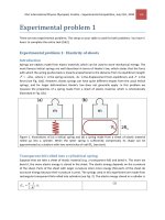
iii. (2.5 pts) Gravitationally the outer layer of the ball is in-
fluenced by the rest just as the rest were compressed into a
point mass. Therefore we have Keplerian motion: the fall of
any part of the outer layer consists in a halfperiod of an ultra-
elliptical orbit. The ellipse is degenerate into a line; its foci are
at the ends of the line; one focus is at the center of the ball (by
Kepler’s 1
st
law) and the other one is at r
0
, see figure (instead
of a degenerate ellipse, a strongly elliptical ellipse is depicted).
The period of the orbit is determined by the longer semiaxis of
the ellipse (by Kepler’s 3
rd
law). The longer semiaxis is r
0
/2
and we are interested in half a period. Thus, the answer is
equal to the halfperiod of a circular orbit of radius r
0
/2:
2π
2t
r→0
2
r
0
2
=
Gm
(r
0
/2)
2
=⇒ t
r→0
= π
r
3
0
8Gm
.
Alternatively, one may write the energy conservation law
˙r
2
2
−
Gm
r
= E (that in turn is obtainable fr om Newton’s
II law ¨r = −
Gm
r
2
) with E = −
Gm
r
0
, separate the variables
(
dr
dt
= −
2E +
2Gm
r
) and write the integral t = −
dr
√
2E+
2Gm
r
.
This integral is probably not calculable during the limitted
time given during the Olympiad, but a possible approach can
be sketched as follows. Substituting
2E +
2Gm
r
= ξ and
√
2E = υ, one gets
t
∞
4Gm
=
∞
0
dξ
(υ
2
− ξ
2
)
2
=
1
4υ
3
∞
0
υ
(υ − ξ)
2
+
υ
(υ + ξ)
2
+
1
υ − ξ
+
1
υ + ξ
dξ.
Here (after shifting the variable) one can use
dξ
ξ
= ln ξ and
dξ
ξ
2
= −
1
ξ
, finally getting the same answer as by Kepler’s laws.
iv. (1.7 pts) By Clapeyron–Mendeleyev law,
p =
mRT
0
µV
.
Work done by gravity to compress the ball is
W = −
p dV = −
mRT
0
µ
4
3
π r
3
3
4
3
π r
3
0
dV
V
=
3mRT
0
µ
ln
r
0
r
3
.
The temperature stays constant, so the internal energy does not
change; hence, according to the 1
st
law of thermodynamics, the
compression work W is the heat radiated.
v. (1 pt) The collapse continues adiabatically.
pV
γ
= const =⇒ TV
γ−1
= const.
∴ T ∝ V
1−γ
∝ r
3−3γ
∴ T = T
0
r
3
r
3γ−3
.
vi. (2 pts) During the collapse, the gravitational energy is con-
verted into heat. Since r
3
≫ r
4
, The released gravitational en-
ergy can be estimated as ∆Π = −Gm
2
(r
−1
4
−r
−1
3
) ≈ −Gm
2
/r
4
(exact calculation by integration adds a prefactor
3
5
); the ter-
minal heat energy is estimated as ∆Q = c
V
m
µ
(T
4
− T
0
) ≈
c
V
m
µ
T
4
(the approximation T
4
≫ T
0
follows from the result
of the previous question, when combined with r
3
≫ r
4
). So,
∆Q =
R
γ−1
m
µ
T
4
≈
m
µ
RT
4
. For the temperature T
4
, we can use
the result of the previous question, T
4
= T
0
r
3
r
4
3γ−3
. Since
initial full energy was approximately zero, ∆Q + ∆Π ≈ 0, we
obtain
Gm
2
r
4
≈
m
µ
RT
0
r
3
r
4
3γ−3
=⇒ r
4
≈ r
3
RT
0
r
3
µmG
1
3γ−4
.
Therefore,
T
4
≈ T
0
RT
0
r
3
µmG
3γ−3
4−3γ
.
Alternatively, one can obtain the result by approximately
equating the hydrostatic pres sure ρr
4
Gm
r
2
4
to the gas pressure
p
4
=
ρ
µ
RT
4
; the result will be exactly the same as given above.
— page 5 of 5 —
Problem T1. Focus on sketches (13 points)
Part A. Ballistics (4.5 points)
i. (0.8 pts)
z
0
= v
2
0
/2g
k = g/2v
2
0
ii. (1.2 pts) The sketch of the trajectory:
iii. (2.5 pts)
v
min
= 3
gR
2
— page 1 of 5 —
Part B. Air flow around a wing (4 points)
i. (0.8 pts)
v
P
= 23 m/s
ii. (1.2 pts) Mark on this fig. the point Q. Use it also for taking measurements (questions i and iii).
Formulae motivating
the choice of point Q: av = const
p +
1
2
ρv
2
= const
p
1−γ
T
γ
= const
iii. (2.0 pts)
Formula: v
crit
= c
2c
p
∆T
a
2
− c
2
Numerical: v
crit
≈ 23 m/s
— page 2 of 5 —
Part C. Magnetic straws (4.5 points)
i. (0.8 pts)
Sketch her e five
magnetic field lines.
ii. (1.2 pts)
T =
Φ
2
2µ
0
πr
2
iii. (2.5 pts)
F =
4 −
√
2
8πµ
0
Φ
2
l
2
— page 3 of 5 —
Problem T2. Kelvin water dropper (8 points)
Part A. Single pipe (4 points)
i. (1.2 pts)
r
max
=
3
3σd
4ρg
ii. (1.2 pts)
Q = 4πε
0
ϕr
iii. (1.6 pts)
ϕ
max
= 2
σr/ε
0
Part B. Two pipes (4 points)
i. (1.2 pts)
Q
0
= 2π ε
0
qr
max
/C
ii. (1.5 pts)
q(t) = q
0
e
γt
, γ =
πε
0
n
C
3
6σd
ρg
.
iii. (1.3 pts)
U
max
=
6
H
3
gσ
2
ρd
2
6ε
3
0
— page 4 of 5 —
Problem T3. Protostar formation (9 points)
i. (0.8 pts)
n = 8
ii. (1 pt)
t
2
≈
0.1r
3
0
Gm
iii. (2.5 pts)
t
r→0
= π
r
3
0
8Gm
iv. (1.7 pts)
Q =
3mRT
0
µ
ln
r
0
r
3
v. (1 pt)
T (r) = T
0
r
3
r
3γ−3
vi. (2 pts)
r
4
≈ r
3
RT
0
r
3
µmG
1
3γ−4
T
4
≈ T
0
RT
0
r
3
µmG
3γ−3
4−3γ
— page 5 of 5 —