Đề thi Thực hành Vật lý Olympic quốc tế 2012
Bạn đang xem bản rút gọn của tài liệu. Xem và tải ngay bản đầy đủ của tài liệu tại đây (5.09 MB, 5 trang )
The 43
rd
International Physics Olympiad — Experimental Competition
Tartu, Estonia — Thursday, July 19
th
2012
• The examination lasts for 5 hours. There are 2 problems
worth in total 20 points. There are two tables in your
disposal (in two neighbouring cubicles), the apparatus of
Problem E1 is on one table and the apparatus of Prob-
lem E2 is on the other table; you can move freely between
these tables. However, you are not allowed to move
any piece of experimental setup from one table to
the other.
• Initially the experimental equipment on one table is
covered and on the other table is boxed. You must
neither remove the cover nor open the box nor
open the envelope with the problems before the
sound signal of the beginning of competition
(three short signals).
• You are not allowed to leave your working place
without permission. If you need any assistance (mal-
functioning equipment, broken calculator, need to
visit a restroom, etc), please raise the corresponding flag
(“help” or “toilet” with a long handle at your seat)
above your seat box walls and keep it raised until an or-
ganizer arrives.
• Use only the front side of the sheets of paper.
• For each problem, there are dedicated Solution Sheets
(see header for the number and pictogramme). Write
your solutions onto the appropriate Solution Sheets. For
each Problem, the Solution Sheets are numbered; use the
sheets according to the enumeration. Copy the final an-
swers into the appropriate boxes of the Answer Sheets.
There are also Draft papers; use these for writing things
which you don’t want to be graded. If you have written
something what you don’t want to be graded onto the
Solution Sheets (such as initial and incorrect solutions),
cross these out.
• If you need more paper for a certain problem, please raise
the flag “help” and tell an organizer the problem num-
ber; you are given two Solution sheets (you can do this
more than once).
• You should use as little text as possible: try to
explain your solution mainly with equations, numbers,
tables, symbols and diagrams.
• Avoid unnecessary movements during the experimental
examination and do not shake the walls of your cubicle -
the laser experiment requires stability.
• Do not look into the laser beam or its reflections! It may
permanently damage your eyes!
• The first single sound signal tells you that there are 30
min of solving time left; the second double sound signal
means that 5 min is left; the third triple sound signal
marks the end of solving time. After the third sound
signal you must stop writing immediately. Put all
the papers into the envelope at your desk. You are not
allowed to take any sheet of paper out of the room.
If you have finished solving before the final sound signal,
please raise your flag.
— page 1 of 5 —
Problem E1. The magnetic permeability of water
(10 points)
The effect of a magnetic field on most of substances other
than ferromagnetics is rather weak. This is b ecause the energy
density of the magnetic field in substances of relative magnetic
permeability µ is given by the formula w =
B
2
2µµ
0
, and typically
µ is very close to 1. Still, with suitable experimental techniques
such effects are firmly observable. In this problem we study the
effect of a magnetic field, created by a permanent neodymium
magnet, on water and use the results to calculate the magnetic
permeability of water. You are not asked to estimate any
uncertainties throughout this problem and you do not
need to take into account the effects of surface tension.
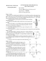
The setup comprises of 1 a stand (the highlighted numbers
correspond to the numbers in the fig.), 3 a digital caliper,
4 a laser pointer, 5 a water tray and 7 a cylindrical
permanent magnet in the water tray (the magnet is axially
magnetised). The water tray is fixed to the base of the stand
by the magnet’s pull. The laser is fixed to the calip er, the base
of which is fastened to the stand; the caliper allows horizontal
displacement of the laser. The on-off button of the laser can be
kept down with the help of 13 the white conical tube. Do not
leave the Laser switched on unnecessarily. The depth of the
water above the magnet should be reasonably close to 1 mm (if
shallower, the water surface becomes so curved that it will be
difficult to take readings from the screen). 15 A cup of water
and 16 a syringe can be used for the water level adjustment
(to raise the level by 1 mm, add 13 ml of water). 2 A sheet of
graph paper (the “screen”) is to be fixed to the vertical plate
with 14 small magnetic tablets. If the laser spot on the screen
becomes smeared, check for a dust on the water surface (and
blow away).
The remaining legend for the figure is as follows: 6 the point
where the laser beam hits the screen; 11 the LCD screen of
the caliper, 10 the button which switches the caliper units
between millimeters and inches; 8 on-off switch; 9 button
for setting the origin of the caliper reading. Beneath the laser
pointer, there is one more button on the caliper, which tem-
porarily re-sets the origin (if you pushed it inadvertently, push
it once again to return to the normal measuring mode).
Numerical values for your calculations:
Horizontal distance between the magnet’s centre and the
screen L
0
= 490 mm. Check (and adjust, if needed) the align-
ment of the centre of the magnet in two perpendicular direc-
tions. The vertical axis of the magnet must intersect with the
laser beam, and it must also intersect with 12 the black line
on the support plate.
Magnetic induction (magnetic field strength) on the
magnet’s axis, at a height of 1 mm from the flat surface,
B
0
= 0.50 T
Density of water ρ
w
= 1000 kg/m
3
Acceleration of free-fall g = 9.8 m/s
2
Permeability of a vacuum µ
0
= 4π × 10
−7
H/m
WARNINGS:
⋄ The laser orientation is pre-adjusted, do not move it!
⋄ Do not look into the laser beam or its reflections!
⋄ Do not try to remove the strong neodymium magnet!
⋄ Do not put magnetic materials close to the magnet!
⋄ Turn off the laser when not used, batteries drain in 1 h!
— page 2 of 5 —
Part A. Qualitative shape of the water surface (1 points)
When a cylindrical magnet is placed below water surface, the
latter becomes curved. By observation, determine the shape
of the water surface above the magnet. Based on this observa-
tion, decide if the water is diamagnetic (µ < 1) or paramagnetic
(µ > 1).
Write the letter corresponding to the correct option into the
Answer Sheet, together with an inequality µ > 1 or µ < 1.
For this part, you do not need to justify your answer.
Part B. Exact shape of the water surface (7 points)
Curving of the water surface can be checked with high sensit-
ivity by measuring the reflection of the laser beam from the
surface. We use this effect to calculate the dependence of the
depth of the water on the horizontal position above the magnet.
i. (1.6 pts) Measure the dependence of the vertical position
y of the laser sp ot on the screen on the caliper reading x (see
figure). You should cover the whole usable range of caliper
displacements. Write the results into the Table in the Answer
Sheet.
ii. (0.7 pts) Draw the graph of the measured dependence.
iii. (0.7 pts) Using the obtained graph, determine the angle
α
0
between the beam and the horizontal surface of the water.
iv. (1.4 pts) please note that the slope (tan β) of the water
surface can be expressed as follows:
tan β ≈ β ≈
cos
2
α
0
2
·
y − y
0
− (x − x
0
) tan α
0
L
0
+ x − x
0
,
where y
0
is the vertical position of the laser spot on the screen
when the beam is reflected from the water surface at the axis
of the magnet, and x
0
is the respective position of the caliper.
Calculate the values of the slop e of the water surface and enter
them into the Table on the Answer Sheet. Please note that it
may be possible to simplify your calculations if you substitute
some combination of terms in the given expression for the slope
with a reading from the last graph.
v. (1.6 pts) Calculate the height of the water surface relative
to the surface far from the magnet, as a function of x, and
write it into the Table on the Answer Sheet.
vi. (1.0 pts) Draw the graph of the latter dependence. In-
dicate on it the region where the beam hits the water surface
directly above the magnet.
Part C. Magnetic permeability (2 points)
Using the results of Part B, calculate the value of µ − 1 (the
so-called magnetic susceptibility), where µ is the relative mag-
netic permeability of the water. Write your final formula and
the numerical result into the Answer Sheet.
— page 3 of 5 —
Problem E2. Nonlinear Black Box (10 points)
In simple problems, electrical circuits are assumed to con-
sist of linear elements, for which electrical characteristics are
directly proportional to each other. Examples include res-
istance (V = RI), capacitance (Q = CV ) and inductance
(V = L
˙
I = L
dI
dt
), where R, C and L are constants. In this
problem, however, we examine a circuit containing nonlinear
elements, enclosed in a black box, for which the assumption of
proportionality no longer holds.
The setup comprises a multimeter (labelled “IPhO-
measure”), a black box that acts as a current source, a black
box containing nonlinear elements, and four test leads with
stackable connectors for wiring. Be careful not to break the
seal on the black box.
The multimeter can measure current and voltage simultan-
eously. You can store with it up to 2000 data points, each
consisting of: voltage V , current I, power P = IV , resistance
R = V /I, voltage time derivative
˙
V (=
dV
dt
), current time deriv-
ative
˙
I (=
dI
dt
) and time t. See multimeter manual for details.
If you go beyond 2000 stored data p oints, the oldest data will
be overwritten.
OUTIN
Multimeter
GND
A V
The constant current source supplies stable current as long as
the voltage across its terminals stays between −0.6125 V and
0.6125 V. When switched off, the constant current source be-
haves as a large (essentially infinite) resistance.
Current source
+
-
I=6mA
U=-612.5mV 612.5mV
The black box contains an electric double layer capacitor
(which is a slightly nonlinear high capacitance capacitor), an
unknown nonlinear element, and an inductor L = 10 µH of
negligible resistance, switchable as indicated on the circuit dia-
gram. The nonlinear element can b e considered as a resistance
with a nonlinear dependence between the voltage and the cur-
rent [I(V ) is a continuous function of V with I(0) = 0]. Like-
wise, for the capacitor, the differential capacitance C(V ) =
dQ/dV is not exactly constant.
We say that the voltage on the black box is positive
when the potential on its red terminal is higher than
the potential on the black terminal. Positive voltage
will be acquired when the terminals of matching col-
ours on the black box and the current source are con-
nected (you are allowed to use negative voltages).
Black box
Nonlinear
device
+
-
C(V)
It is safe to discharge the capacitor in the black box by shorting
its inputs, either by itself or through the IN and OUT termin-
als on multimeter: the internal resistance of this capacitor is
enough to keep the current from damaging anything.
You are not asked to estimate any uncertainties
throughout this problem.
Part A. Circuit without inductance (7 points)
In this part, keep the switch on the black box closed (push “I”
down), so that the inductance is shorted. Please note that
some measurements may take a considerable time, therefore it
is recommended that you read through all the tasks of part A
to avoid unnecessary work.
i. (1.0 pts) Confirm that the output current of the current
source is approximately 6 mA, and determine the range within
which it varies for voltages between 0 and +480 mV. Document
the circuit diagram used.
ii. (1.2 pts) Show that the differential capacitance C(V ) used
in the black box is approximately 2 F by measuring its value
for a single voltage of your choice C(V
0
) = C
0
. Document the
circuit diagram.
iii. (2.2 pts) Neglecting the nonlinearity of the capacitance
[C(V ) ≈ C
0
], determine the current–voltage characteristic of
the nonlinear element used in the black box. Plot the I(V )
curve for obtainable positive voltages on the black box onto
the answer sheet. Document the circuit diagram.
iv. (2.6 pts) Using measurements taken from the whole range
of obtainable voltages, calculate and plot the C(V ) curve for
obtainable positive voltages from the black box on the answer
sheet. Write down the minimal and maximal values of differ-
ential capacitance C
min
, C
max
. Document the circuit diagram.
Part B. Circuit with inductance (3 points)
Enable the inductance by opening the switch on the black box
(push “0” down). Using the same method as in pt. A-iii, meas-
ure and plot the current-voltage characteristic of the nonlin-
ear element. Describ e any significant differences between the
curves of parts A and B and suggest a reason using qualitative
arguments. You need to know that the nonlinear element also
has a capacitance (≈ 1 nF) which is connected in parallel to
the nonlinear resistance.
— page 4 of 5 —
IPhO-measure: short manual
IPhO-measure is a multimeter capable of measuring voltage V
and current I simultaneously. It also records their time derivat-
ives
˙
V and
˙
I, their product P = V I, ratio R = V/I, and time
t of the sample. Stored measurements are organized into sep-
arate sets; every stored sample is numbered by the set number
s and a counter n inside the set. All saved samples are written
to an internal flash memory and can later be retrieved.
Electrical behaviour
The device behaves as an ammeter and a voltmeter connected
as follows.
OUTIN
Multimeter
GND
A V
Internal
Range resistance
Voltmeter 0 . . . 2 V 1 MΩ
Voltmeter 2. . . 10 V 57 kΩ
Ammeter 0 . . . 1 A 1 Ω
Basic usage
• Push “Power” to switch the IPhO-measure on. The
device is not yet measuring; to start measuring, push
“start”. Alternatively, you can now start browsing your
stored data. See below.
• To browse previously saved samples (through all sets),
press “Previous” or “Next”. Hold them down longer
to jump directly between sets.
• While not measuring, push “Start” to start measuring
a new set.
• While measuring, push “Sample” each time you want to
store a new set of data (i.e. of the readings shown on the
display).
• While measuring, you can also browse other samples of
the current set, using “Previous” and “Next”.
• Press “Stop” to end a set and stop measuring. The
device is still on. You are ready to start a new meas-
uring session or start browsing stored data.
• Pushing “Power” turns the device off. The device will
show text ”my mind is going ”; do not worry, all the
data measurements will be stored and you will be able to
browse them after you switch the device on again. Saved
samples will not be erased.
Display
A displayed sample consists of nine variables:
1. index n of the sample in the set;
2. index s of the set;
3. time t since starting the set;
4. voltmeter output V ;
5. rate of change of V (the time derivative
˙
V ); if derivative
cannot be reliably taken due to fluctuations, “+nan/s” is
shown;
6. ammeter output I;
7. rate of change of I (the time derivative
˙
I); if derivative
cannot be reliably taken due to fluctuations, “+nan/s” is
shown;
8. product P = V I;
9. ratio R = V/I.
If any of the variables is out of its allowed range, its display
shows “+inf” or “-inf”.
— page 5 of 5 —