Information Technology (IT)
Bạn đang xem bản rút gọn của tài liệu. Xem và tải ngay bản đầy đủ của tài liệu tại đây (296.8 KB, 43 trang )
- 1 -
Chapter 1
Introduction
1.1 Background
We are now in the information era. Information Technology (IT) has been extensively
used in almost all areas of the human life. Especially in manufacturing today, Computer
Numerical Control (CNC) machines, Computer Aided Design (CAD), Computer Aided
Manufacturing (CAM) systems are among the most important applications of the information
technology in manufacturing, which, in this research, will be called summarily as Computer
Aided Technology or CAT for short.
CNC machines, CAD, CAM, have been applied widely not only in the developed
countries, such as the United States, Japan, Germany, but also in developing countries like
Thailand, India, China, Taiwan and South Korea. For example, in South Korea, from 1986 to
1990, the total value of CNC machines, CAD, CAM used in manufacturing increased from 289
to 420 US$ millions. Such applications grow at the rate of 50% annually in South Korea (Jang
Seung Hwan, 1988).
The US embargo, which did not allow the transfer of IT into Vietnam, was lifted in early
1994. Consequently, Vietnam is very out of date in terms of IT application. Observation shows
that up to 1990, there were only 10,000 personal computers in Vietnam. (Adam Schwarz, 1995)
However, in recent years, with the "Open door" policy, IT has been gradually introduced
in Vietnam. At the beginning of 1995 the number of computers in Vietnam reached about
50,000, and is growing at the rate of about 40% annually (Adam Schwarz, 1995). Its
applications, however, are restricted mostly to office management. In enterprises, IT is used in
storing data, accounting, and administrative work. IT is rarely applied in manufacturing.
Machine tool is one of the biggest industries in the manufacturing sector in Vietnam.
However, the machines and equipment are old and obsolete, which have been in operation for
twenty or thirty years. CNC machines, CAD, CAM are almost never used except some research
centers such as the Research Institute of Machinery, the Design Institute of Chemical Industry,
and the Hanoi University of Technology.
Low technology used in the machine tool industry is seen as one of major reasons for
low quality of products. Combined with low management skills, this leads to losing customers,
and poor or even disastrous financial performance of many state-owned enterprises in recent
years. In the emerging market economy of Vietnam, in order to compete effectively with
foreign enterprises with high technology, and with the imported machine tools, the applications
of CNC machine, CAD, and CAM systems become an immediate survival need for the
domestic machine tool companies. The increasingly critical demands of customers in terms of
designing, functioning, working life, productivity, ease in use and precision, also require CNC
machine, CAD, CAM systems to be introduced.
1.2 Statement of Problem and Significance of the Study
- 2 -
As IT and CAT are very new for the country. Managers of machine tool companies in
Vietnam do not know how CNC machines, CAD, and CAM can benefit them, what conditions
are required to introduce these technologies in their companies. As a consequence, they do
not know how to develop a plan to introduce CNC machine, CAD, CAM effectively, especially
when the production and market conditions are changing almost daily in the country.
At the same time, many foreign investors are ready to transfer technological know how
to the manufacturing sector in Vietnam, but they do not understand the major difficulties
Vietnamese enterprises are facing.
Introducing all these technologies at the same time would be extremly difficult, if not at
all impossible, for any Vietnamese machine tool firm. Therefore, a major question is what
priority order among CNC machine, CAD, CAM should is most appropriate to go ahead for a
Vietnam enterprise in machine tool firm, is still in question.
1.3 Objectives
The study aims at helping managers in machine tool enterprises in Vietnam gain insight
into how these technologies can be introduced in their companies. It may also provide
suppliers of CNC machine, CAD, CAM some preliminary ideas about how a Vietnamese
enterprise can apply them. Furthermore, it is expected to provide some suggestions to assist
the formulation of appropriate policies to encourage the overall objective of the government of
Vietnam to "catch " in the more advanced technology.
To achieve these goals, this research steps out the following specific objectives:
1. To develop a model for analyzing major factors in introducing of CAT in manufacturing
industry in Vietnam
2. To apply the model in one company in machine tool firm in Vietnam to analyze
conditions for introducing CAT.
3. To suggest recommendations regarding CAT introduction to the company based on the
analysis.
1.4 Scope and Limitations
CAT has many applications in manufacturing, the study focuses only on CNC machines,
CAD, CAM which means that issues like manufacturing resource planning (MRP II) system, or
flexible manufacturing system (FMS) will not fall into the scope of the study, also the research is
limited to the machine tool firms in Vietnam.
The analysis is carried out based on qualitative information gathered through secondary
information sources and direct interview of relevant managers in the company under study.
There is not sufficient information about applications of CNC machine, CAD, and CAM of foreign
companies to make comparison, so it lacks comparative analysis.
- 3 -
1.5 Organization of the Report
The research is carried out in 5 steps .
1. Literature Review
A review of the literature aims at an overall understanding of information technology,
CAT and its applications in manufacturing. The experiences in CAT applications of Asian
countries are useful for comparison with Vietnam.
2. Developing a Model
In order to assess the conditions of company for introduction of CNC machine, CAD,
and CAM, a conceptual framework is developed based on the review of literature and personal
knowledge. The framework is presented in the Figure 1.1
3. Data Collection
The data are collected through in-depth interviews with the managers and staff of
various functional departments of the firm under study, information technology development.
Secondary data are the company's internal report articles in public media, and government
documents on policy and regulations.
4. Analyzing and Presenting
This step carries out the analysis of plant conditions in term of CNC machine, CAD,
CAM applications based on the framework developed in step 3. The analysis is presented in
the form of comparison between actual conditions and related requirements to show the gaps
in introduction of CNC machine, CAD, and CAM
5. Making Recommendations
Recommendations for introduction of CNC machines, CAD, CAM to the managers of
the plant under study are based on the analysis and conclusions presented in the previous
chapters, opinions of manager of computer center of design institute of chemical industry, and
manager of CAD department of research institute of machinery, regulations of government of
information technology development to year 2000.
- 4 -
COMPUTER AIDED TECHNOLOGY
APPLICATION
1-Knowledge Infrastructure
2- Internal Assets
3-Management
4-Target Products
ACTUAL
REQUIRED
Constraints
Advantages
Training
Research
Framework for analyzing of factors for CAT applicationFigure 1-1
- 5 -
Chapter 2
Literature Review
2.1 Definition of Information Technology (IT)
There are now many definitions about information technology of authors in different
fields. Each area of application has its own definition. Here are some of them.
-Mc Farlan (1984) stated that IT is "computer remote devices, telecommunications"
-Bakkopoulus (1985): IT is a "set of non-human resources as dedicated to the storage,
processing and communication of information, and way in which these resources are organized
into the system capable of performing a set of tasks".
-Poster and Millar (1985): It must be conceived of broadly to encompass the information
that business create and use as well as a wide spectrum of increasingly convergent and linked
technologies that process the information".
-Gerstin (1987) referred IT to "the collective means to assemble and electronically
stores, transmit, process, and retrieve word, numbers, images and sound, as well as to
electronic means to control machines of all kinds, from every day applicant to vast automated
factories".
The single definition of IT widely accepted and used is the "use of computers and
computer related technology", (Guimaraes, et all, 1988). This definition is most suitable for
manufacturing and will be adopted in this research.
2.2 IT in manufacturing: Computer Aided Technology (CAT)
Computer aided technology (CAT) implies applications of information technology in
manufacturing. At the CAT ' 91 conference in Bangkok, Pier Mercier, consultant of D. Appleton
Company Europe, defined that CAT is a new set of technical tactic alternatives that may be
used to achieve strategic objectives. CAT is seen as tactics, not strategy. CAT is single tool
that can improve productivity, product quality and reliability and cost reduction. Mikell Groover
(1987) viewed CAT as directing the technology of manufacturing toward one goal-the fully
automated factory of the future.
The major reasons for applying in CAT in engineering are product- related for discrete
industries, and process- related for process industries. In the discrete industries the aim of
using CAT is to reduce the time and cost of designing products and to increase product quality.
In the process industries the focus is the design of the process, and the integration of the
production equipment. The major areas in which technology can be applied in designing
process are design synthesis, design analysis, documentation, simulation, preparation, and
planning of the manufacturing process. The selection of the area in which technology will be
applied depends on the company and the industry sectors.( John Stark, 1992).
- 6 -
In engineering, after 30 years of applying computer. It could be thought that great
productivity gains would have been achieved in this area, and that there would not be much
more progress to be made. Yet the situation is completely the opposite. Very few companies
have made significant productivity gains through the use of computers in product development,
and there is still a lot more progress to be made. Some companies have benefited greatly from
the use of computers in product development.
In 1970s uses of computer in product development mainly were Computer Aided
Design, Numerical Control Programming, Finite Element Analysis, Computer Aided Process
Planning, Simulation, Computer Aided Technical Publications, Robot programming. In 1990s,
computers are mostly used in product development, engineering data management, product
modeling, engineering data exchange, information models, integration, engineering system
procedures, training (John Stark, 1992)
Operations in the manufacturing are at the heart of any enterprise. They are affected
strongly by production management activities. CAT applications in the production can make
real difference in the day to day operations and in the role of the people. Finally the quality of
working life can be significantly improved. Jobs are enriched and no longer dominated by old
and inflexible technology. Flexible automation can be introduced in production, particularly for
replacing manual labor in repetitive operations such as welding, assembly, and painting.
Technological integrated factories can take advantages of flexible manufacturing systems that
are able to handle a large variety of products economically.
Advanced methods, supported by CAT, are becoming increasingly common in the
factories. Its applications are all being used the fabrication of parts. Mechanical assembly
equipment, usually reserved for very high-volume products with simple assembly process is
most frequently are now almost always present in large, modern factories. Handing technology
include robots, pick-and-place devices for assembly, machine loading, and palletizing.
The application of CAT can: 1.Create a streamlined process in engineering and design,
fabrication, and assembly of products 2.Improve use of scare human resources, the product
quality increase, and job's satisfaction employees are satisfied with the jobs. 3.Improve cost
structure (Pierr Merceir, 1991).
2.3 Components of CAT: CNC machine, CAD, CAM
According to Pierr Merceir (1991), the components of CAT include computer aided
design (CAD), computer numerical control machine (CNC), flexible manufacturing system
(FMS), robotics, and computer aided manufacturing (CAM). According to Mikell Groover (1987)
CAM consist of Computer aided process planning (CAPP), Material Requirements Planning
(MRP), Direct numerical control (DNC); Manufacturing Resource Planning (MRPII); Shop Floor
Data Collection, Computer aided inspection (CAI), Computerized quality control (CAQ).
Given time limitation of this study, and the current manufacturing environment and
policy in Vietnam, this research will concentrate only on 3 major components: CNC machine,
CAD, and CAM which will be described in details below.
2.3.1 Computer Numerical Control Machine (CNC machine)
- 7 -
CNC was a significant achievement of development of numerical control (NC)
technology in batch and job shop manufacturing. It was introduced in the mid to late 1960s and
was commercially offered during early 1970s.
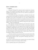
Computer numerical control machine is a numerical system using a dedicated
microcomputer as the machine control unit. CNC systems utilize microcomputer to store
machining programs in read-only memories (ROM).
Tape
reader
for initial
program
entry
NC
program
storage
Microcomputer
( software
function )
Computer-
hardware
Interface and
servo
system
====>
<==== Machine tools
Figure 2.1 General configuration of a computer numerical control (CNC) system
(Source: Mikell Groover, 1987)
Figure 2.1 above shows the process of operating CNC machine the machining
programmed- which are in the form of tape- are transferred into "Tap-reader". In this stage all
program are read. Then they are stored in the " NC program storage". Microcomputer, which is
a functioning software, control the stored programs. The relevant commands are transferred to
the "machine tools" to process, through the " inter face and servo system". As conventional
machines, CNC machine is mainly used to lathe, to bore, and grind, etc. The only difference
between CNC machine and conventional machine is that in CNC machine every operation is
controlled by computer, rather than worker in conventional machines.
Their advantages include their adaptability to different types of machine tools, ease of
programming, and information retrieval, and the ability of one computer to simultaneously
control one or more machine tools (UNIDO/ESCAP by technonet Asia Singapore, Nov. 1986)
The advantages of computer numerical control over conventional NC are:
1.The part program tape and tape reader are used only once to enter the program into
memory. The results in improved reliability, since the tape reader is commonly considered the
last reliable component of the conventional NC system; 2.Tape editing at machine site. The NC
tape can be optimized during tape tryout at the site of the machine tool; 3. Greater flexibility.
The most significant advantage over conventional NC is CNC's flexibility. New options can be
added to the system easily and at relatively low cost; 4. Metric conversion. CNC can
accommodate conversion of tapes prepared in units of inches into the international system; 5.
Total manufacturing system. CNC is more compatible with the use of a total manufacturing
system. ( Mikell Groover, 1987).
2.3.2 Computer Aided Design (CAD)
CAD was introduced in 1960s. At the begin of 1970s it is applied strongly in developed
countries. Now it is used widely in different countries in the world, and becomes a very useful
tool to gain competitive advantages.
- 8 -
Mikell Groover (1987) defined CAD as any design activity that involves the effective use
of the computer to create, modifies, or document an engineering design. CAD is most
commonly associated with the use of an interactive computer graphics system.
A computer aided design system can beneficially be used in four phases of the design
process.
1. Synthesis (geometric modeling).
The geometric modeling is concerned with the use of a CAD system to develop a mathematical
description of the geometry of an object. The mathematical description permits the user of the
CAD system to display an image of the model on a graphics terminal and to perform certain
operations on the middle. These operations include creating new geometric models from basic
building blocks available in the system, moving the images around on the screen, zooming in
on certain features of the image. These capabilities permit the designer to construct a model of
a new product or to modify an existing model.
There are various types of geometric models used in computer aided design. One
classification distinguishes between two-dimensional models. Two-dimensional models are best
utilized for design problems in two dimensions, such as flat objects and layout of buildings.
Three-dimensional CAD systems are capable of modeling an object in three dimensions. The
operation and transformations on the model are done by the system according to the user
instructions in three dimensions.
Geometric models in CAD can also be classified as being either wire-frame models or
solid models. A wire-frame model uses interconnecting lines to depict an object. Wire-frame
model of complicated geometry can become somewhat confusing because all of the lines
dipping the shape of the object are usually shown, even the lines representing the other side of
the object. Solid models are a more resent development in geometric modeling. More important
for engineering purposes, the geometric model is stored in the CAD system as a three-
dimensional solid model, thus providing a more accurate representation of the object.
2. Analysis and Optimization (engineering analysis)
Some forms of engineering analysis must often be performed as part of the design
process. The analysis may take the form of stress-strain calculations, heat transfer analysis, or
dynamic simulation. Two examples of the software typically offered on CAD system are mass
properties and finite -element analysis. Mass properties analysis involves the computation of
such features of a solid object as volume, surface, area, weight, and center of gravity. The
finite-element analysis is available on most CAD system to aid in heat transfer, stress-strain
and other engineering computations.
3. Evaluation (design review and evaluation).
Some of the CAD features that are helpful in evaluating and reviewing a proposed
design include
* Automatic dimensioning routines, which determine precise distance measures
between surfaces on the geometric model identified by the user
*Interference checking routines, which identify whether two objects occupy the same
place
- 9 -
*Kinematics Routines, used to test the operation of mechanical linkages.
4. Presentation (automated drafting)
CAD system can be used as automated drafting machines to prepare highly accurate
engineering drawing quickly. It is estimated that CAD system increases productivity in the
drafting function by about fivefold over manual preparation of the drawings. (Mikell Groover,
1987)
A Typical CAD System
A typical commercially available computer aided design system consists of components :
*One or more design workstations
*Processor
*Secondary storage
*Plotter and or other output devices
Secondary
storage
CPU
Output
Plotters, etc
Graphics
terminal
Input devices
Design workstation
Figure 2.2 Configuration of a typical CAD system
Source: Emory, Zimmer, Mikell Groover, Englewood,NJ, 1984
The design workstation is the interface between CAD system and the user. For the user
to accomplish the various phases of the design process, the workstation must be able to
receive input instructions from the user and to display output data and graphics to the user.
Operator input devices are used for the input functions. The input devices for a CAD system
typically include an alphanumeric keyboard, electronic keypad or other device to input special
graphic functions and a cursor control device ( e.g., a light pen, " mouse" ,joystick, or electric
tablet and " puck"). The graphical design out put is accomplished by means of a graphics
display monitor. The processor is the CAD system computer . Connected to the processor is a
- 10 -
secondary storage for application program and design data. Also connected to the processor
are more or one output devises such as X-Y plotters, electrostatic plotters and similar
equipment used for automated drafting function (Mikell Groover, 1987)
The important reasons for using a computer-aided design system to support the
engineering design function:
1. To increase the productivity of the designer. This is accomplished by helping the
designer to conceptualize the product and its components. In turn this helps to reduce the time
required by the designer to synthesize, analyze, and document the design.
2. To improve the quality of the design. The uses of a CAD system with appropriate
hardware and software capabilities permit the designer to do a more complete engineering
analysis and to consider a large number and variety of design alternatives. The quality of the
resulting design is thereby improved.
3. To improve design documentation. The graphical output of a CAD system result in
better documentation of the design than what is practical with manual drafting. The engineering
drawings are superior, and there is more standardization among the drawings, fewer drafting
errors, and greater legibility.
4. To create manufacturing data base. In the process of creating the documentation for
the product design (geometric specification of the product, dimensions of the components,
material specification, bill of material, etc.), Much of the required data base to manufacture the
product is also created (Mikell Groover, 1987)
2.3.3 Computer Aided Manufacturing (CAM)
Mikell Groover (1987) defined CAM as the effective use of computer technology in the
planning management and control of the manufacturing function. In his view the applications of
CAM consist of two broad
categories:
1-Manufacturing planning
2-Manufacturing control
The two categories represent two different levels of involvement of the computer in the
operation of the plant. The details of its applications are reviewed below:
a-In Manufacturing Planning
CAM applications for manufacturing planning are those in which the computer is used indirectly
to support the production function, but there is no direct connection between the computer and
the process. The computer is used "off-line" to provide information for the effective planning
and management of production activities. The important applications of CAM are:
-Cost estimating
-Computer-aided process planning (CAPP)
-Computerized machine ability data systems
-Computer-assisted NC part programming
- 11 -
-Development of work standards
-Computer-aided line balancing
-Production and inventory planning
-Material requirements planning (MRP)
Material requirements planning (MRP) are a computational technique that converts the
master schedule for end products into a detailed schedule for the raw materials and
components used in the end products. Material requirement planning has two majors
objectives: determine requirements and keep the priorities current. The main object of any
manufacturing planning and control system is to have the right materials in the right quantities
available at the right time to meet the demand for the firm's products. The MRP's objective is to
determine what components are needed in order to meet the master production schedule and,
on the basis of lead time, to calculate the time periods when the components must be
available. It must then determine what to order, how much to order, when to order, when to
schedule delivery.(J.R.Tony Arhold, 1992)
The inputs to MRP system are master production schedule, Inventory records, bill of
material. The master production schedule is a statement of which end items are to be
produced, the quantity of each, and the dates they are to be completed. Inventory is a major
input to the MRP system. When a calculation is made to find out how many are needed, the
quantities on hand must be taken into account. The bills of material are one of the most
important documents in a manufacturing company.
Computer-aided process planning (CAPP) represents the link between design and
manufacturing in a CAD/CAM system. It concerned with determining of processing and
assembly steps that must be accomplished to make the product. The processing sequence is
documented on a form called a route sheet. The route sheet typically list the production
operations, machine cells, or workstations where each operation is performed, fixtures and
tooling required, and the standard time for each task.
There are two types of CAPP (1) Retrieval CAPP systems; (2) Generative CAPP
systems. The Retrieval-type CAPP systems are based on the principles of group technology
and part classification and coding. With these systems, a standard process plan (route sheet)
is stored in the computer files for each part code number. The standard route sheets are based
on an ideal plan that is prepared for each family. The generic CAPP systems represent an
alternative approach to automated process planning. Instead of retrieving and editing an
existing plan contained in a computer data base, a generic system creates the process plan
based on logical procedures similar to the procedure a human planner would use. In a full
generative CAPP system, the process sequence would be planned without a set of predefined
standard plans.(Mikell Groover, 1987).
The benefits of CAPP are (1) Process rationalization and standardization, (2) increased
productivity of process planners, (3)Reduced lead time for process planning, (4) Improved
legibility, (5) Incorporation of other application programs.
b-In Manufacturing Control
Manufacturing control is concerned with managing and controlling the physical
operation in the factory. Process control, quality control, shop floor control, and process
monitoring are included within the scope of this function.
- 12 -
Shop floor control refers to production management techniques for collecting data from
factory operations and using the data to help control production and inventory in the factory.
All of these concepts sever as basic understanding for the study, because we find them
official, and suitable to the objectives of the study and Vietnamese situation than the other
ones.
2.4 The CAT Applications in Thailand and South Korea
In Thailand
Thailand, a neighbor country that has the similar geography, population and national
characteristics to Vietnam. Thailand has a high economic growth. Now, Thailand is more
advanced than Vietnam in applying high technology in manufacturing The learning experiences
of Thailand is beneficial for Vietnam.
In Thailand now, no one uses NC machine tools ( no computer involved) more because
of its inconvenient. Instead of NC, DNC is used widely. DNC is the system of many CNC
machines directly controlled by one computer. DNC has advantages cutting up the step of
making punched steps. There are more than 50 factories having some kind of DNCs in their
factories. There is circumstance that factories have the machines but occasional use them.
There is no experiences operators who can fluently make control programs and operate these
machines (UNIDO/ ESCAP, Thailand report, 1987).
Computer aided design system (CAD ) have not been widely used in small and medium
scaled companies. Only large organizations for example Thai Oil, Siam Cement Group, Thai
International Airline, Petroleum Authority of Thailand have CAD system. Educational institutes
namely Asian Institute of Technology and Chulalongkorn University, College of engineering
have CAD system for research.( UNIDO/ ESCAP Thailand report, 1987).
Some factories have small CAD systems such as Auto CAD in use for drafting.
AutoCAD create many conveniences but it can not efficiently perform calculations for further
design. Auto CAD must be linked with other specific software in order to do calculations.
CAM system used to centrally control DNC machines. CAM is also used to control a
independent CNC machine. The fully integrated CAM system, which do scheduling, planning
and control of operations, are not in use in Thailand.
Most CAM users are not quite successful in having introduced CAM system, they are
not able to utilize CAM full capacity. Although, they can generate volume, have precision,
reduce setup time, they can not achieve full utilization of CAM.
There are many CAD/CAM systems in the use in both private and public organizations.
CAD/CAM system is system in which CAD and CAM are integrated in the uniform
manufacturing system. There are three available for public access. Asian Institute of
- 13 -
Technology (AIT) has a IBM computer aided design system with comprehensive collections of
software. The AIT's system is mainly used for academic research. Chulalongkorn, College of
Engineering are the other public organizations having complete CAD system. The Metalworking
and Machinery Industries Development Institute (MIDI) has 4 computer aided manufacturing
machines as follows 1.Makino Wirecut machine, 2. Makino Electro discharge machine (EDM),
3.Mazak Computer Numerical control Lathe with FUNAC control, 4.Toshiba Computer control
machine center with TOSNAC control. MIDI personnel are learning how to operate machines.
Machines will be use for manufacturing prototype, and for demonstration.
(UNIDO/ESCAP Thailand report, 1987).
Obstacles of introduction of CAD/CAM are lack of personnel who fluently understand
CAM. There is no further development of personnel in intermediate and advance levels. All
such pitfalls of applying CNC machines, CAD, and CAM systems may be good lessons for
Vietnam in introduction of such applications
CAT in South Korea
In 70s, the economic growth in South Korea was seen as a phenomenon. So Korea is
evaluated as one of the four Asian dragons in term of economic growths. South Korea belongs
to the new industrial countries. Therefore the reviewing the introduction of CAT in South Korea
would be useful for Vietnam.
South Korea machine tool industry was in an embryonic stage before the early 1970s
reflecting the generally underdeveloped stage of the machinery, material and part industries.
After the mid-1970s the industry expanded rapidly, aided by the government' machinery
industry. In 1978, the government began to actively assist general machinery, special products,
materials and part-producing companies. During the fifth Five-year Economic Plan, government
designated the machine tool industry as a main exporting sector and it simplified the export
procedures. In additional machine tool fairs both at home and abroad have been help to
exchange advanced technology and to increase importer 's confidence in South Korean
machinery
The first CAD/CAM system was introduced to South Korea in mid 1970s, number of
companies utilized CAD/CAM system. Seventy three (73)companies have used large systems,
and 79 companies have utilized small-sized (under 16 bits) systems. However, most of the
hardware and software systems are imported. The CAD/CAM introduction increased rate of
over 50% annum. Due to the high demand of small and medium sized companies for CAD/CAM
systems, the supply of small CAD/CAM system in domestic market is expected to increase
greatly (Jang, Seung Hwan, 1988).
Large domestic entrepreneurs have actively been introducing a computer aided design
(CAD) and computer aided manufacturing (CAM) in their production to save production costs.
CAD and CAM have been utilized in shipbuilding, automobiles, the electric and electronic field
to enhance the productivity. Samsung has saved manpower and design costs by 60%. Hundai
Motor Co., which introduced the system with a total investment of 7 billion won since 1982, has
applied the computer system in the design of autos and the manufacture of mold presses.
(Jang, Seung Hwan, 1988).
- 14 -
Chapter III
Development of a model for analysing major factors in
introduction of CAT
This chapter aims at designing an analytical model,which will help us, on the one hand,
to understand what are the principal requirements to introduce CNC machine, CAD, and CAM
systems into a machine tool company, and on the other hand, to assess the actual capability of
the company to introduce these technologies.
3.1 Background for the Analytical Framework
There are different approaches in developing a model to show the requirements in
introduction of Computer Aided Technology (CAT) at a firm level.
Chalmet (1987) developed a model for the introduction of a new production technology
in the factory, which consists of five steps as follows:
1- Orientation: Analyzing strengths and weakness of organization and technical-economical
opportunities of factories.
2- Pre-design: Implementing the feasibility studies
3- Design: Specification for tasks of the technical sub-systems
4- Test: Realization of technical sub-systems
5- Implementation: Adjustments of the technical sub-systems.
The model of Chalmet mostly concerns the procedures for implementation of
introduction of a new technology. This model is not so relevant to the objectives of this study.
In the CAT "91 conference in Bangkok", Pierr Meceir presented a framework in which
all factors impacting the introduction of a new technology are divided into five main groups.
They are:
1- Knowledge Infrastructure
2- Internal Assets
3- Target Products
4- Management
5- External Factors
The model of P. Meceir is adopted in this research as it is most closed to the objectives
of the study. The main factors of Pierr Meceir model are discussed in detail in the following
sections.( See Fig. 3.1)
3.2 Knowledge Infrastructure
- 15 -
The knowledge required for each technology - CNC machines, CAD, and CAM systems
are different due to their distinctive functions. The knowledge infrastructure is one of the most
important factors for the application of new technologies.
3.2.1 Knowledge Required For CNC machines
As mentioned in the previous chapter, CNC machines are used to manufacture a part
or machine. Machine operators, programmers, and process planners are people directly
involved in the process of operating CNC machines.
In CNC machine, the process planner does not directly run the production process. He
would decide which machine is to be used to satisfy the technical requirements of a part. The
decisions are made based on the capacity of different machines.
To do so the process planner should have general knowledge on the operation and the
ability of different CNC machine tools. He has to understand how the parts are to be produced.
The process planner usually is a mechanical engineer who has experiences in working with
CNC machines (E.Bohez, 1994).
The task of a programmer is writing part-machining programs for CNC machines to
manufacture. Based on drawings, and with the help of the part-coordinate-system, the
programmer has to establish a process plan. How a part is to be made, what tools and
sequence of operations are to be followed, and at what feed rate and speeds a machine is to
operate, are all included in the process plan. The programmer then writes down the
instructions in the G-code language to build the part program. To be able to make the part
program, the programmer obviously has to master the G-code language and perfect in
machining technology. The mechanical engineers may be good candidates for programmers
(E.Bohez, 1994). In reality, one person can do the jobs of both the programmer and the
process planner. The division between them is very relative.
CNC machine operators are people who directly control the working process of
machines. The machine operators will stand by the machines. When the production is going
on, the instructions are normally displayed on the graphic screen of CNC control. The machine
operator should be able to read them so that he can monitor the machining process and
suggest modification to the program which he can be permitted to do himself or with the
permission of the supervisor. Another important function of the CNC operator is to monitor the
quality of parts, such as surface and tolerances. If the part is out of tolerance, the operator will
have to adjust the tool offset value or change the tool inserted (E. Bohez, 1994).
- 16 -
INTERNAL
ASSETS
Knowledge
Infrastructure
CAM
Mach. Operating
TARGET
PRODUCTS
EXTERNAL
FACTORS
MANAGEMENT
CAD
CNC
Machine
Programming
Building, Workshop
Existing Machines
Capital
Maintenance
Process planning
Commitment
Managing skills
Appraisal ability
Target market
Philosophy
Volume
Quality
Workforce
Government
Supporting industry
Competitors
Suppliers
Variability
Model analyzing factors for introduction
of CAT in MTF
Factors
CAD , CAM using
English, computer
Figure 3-1
C A T
- 17 -
The CNC machine operators have to monitor the CNC machines during production.
They should understand G-code language, and operations of CNC machines. That is because
the instructions, commands, and descriptions on screen are written in G-code language.
Knowledge regarding standards, tolerance, and tools is also required for CNC operators.
3.2.2 The Required Knowledge of CAD Users
CAD, as we already knew, is a software used in designing, drafting, and simulations.
Designers and drafters are the people directly involve in the process of using CAD system.
The tasks of designers are to create parts, or machines. They have to understand how
a part or machine is configured or shaped. Therefore, they have to know engineering drawings,
operating principles of different machines, and dimensions. More specifically, the required
tolerance, precision, how parts can be assembled, uses of different materials, etc. have to be
well understood by designers.
In addition, the designers are required to understand how to draw different shapes on
screen of computer. That means the CAD operators have to know how to create a point, line,
or curve using computer.
The tasks of the drafters are more simple than that of the designers. They have to draw
a part or machine that are initiated by designers. They also can have to modify and make the
designs clearer in technical terms. So the drafters have to know about the engineering drawing.
3.2.3 Knowledge Required for CAM Users
CAM system is software assisting the programming and controlling jobs. Without CAM,
a programmer in CNC machine has to program a machining process manually before recording
it into the machine. So CAM is a further computer application that helps people to program by
computer and then automatically projects the process plan. Then the machining commands are
transferred directly into CNC machines using digital signals. Similarly, CAM system can be
used to program the process of quality control, or for Direct Numerical Control (DNC), etc.
Therefore, the CAM operator should have knowledge of both the programmer and process
planner of CNC machines as mentioned above. That is because the CAM operator has to
understand how and when each stage of manufacturing is done or performed and then uses
CAM system to control this process.
In addition, the CAM operator also has to understand the related areas where CAM
system is used to program for. For example, if a CAM system is used to control the quality of
products, the CAM operator has to know about the quality control. That is why in reality the
CAM operators are different depending on which fields CAM systems are used for.
3.2.4 Computer Knowledge and English Skills
Computer literacy is the first requirement for users of CNC machines, CAD, and CAM
systems. However, the basic requirement on computer knowledge may be different from one
use to other depending on his or her works in such systems. For example, a programmer
should have the ability to program a process by computer is required. A programmer has to
master G-code language to write a program. An operator may only need understanding of G-
code at the level allowing him to communicate effectively with the machine. CAD and CAM