HƯỚNG DẪN SỬA CHỮA ĐỘNG CƠ ZD30 CỦA NISSAN
Bạn đang xem bản rút gọn của tài liệu. Xem và tải ngay bản đầy đủ của tài liệu tại đây (6.33 MB, 74 trang )
ZD30DDTi Common Rail Diesel Engine
Y61 Patrol Wagon
UY61 Cab Chassis
Nissan Australia. July 2008
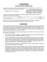
Foreword
The information in this Training Manual should not be interpreted as a basis for
warranty or goodwill claims against Nissan Motor Co. (Australia) Pty. Ltd. (NMA)
unless so designated.
This Technical Training Manual is intended for use by NMA & Nissan
Dealership Technical Personnel. It is not designed for the use by press or for
customer distribution.
Before quoting any specifications be sure to check the relevant Service Manual
and Technical Bulletins.
Right for alteration to data and specifications at any time is reserved. Any such
alterations will be advised by Nissan through Technical and Sales Bulletins.
©2008 Nissan Motor Company (Australia) Pty. Ltd.
Inc. Victoria
Ref: Technical Training Department.
1
ZD30DDTi CRD Engine
Nissan Australia July 2008
ABOUT THIS TRAINING MANUAL
The purpose of this document is for Nissan Dealer Technical Staff SELF STUDY purposes. If anything
contained within this document gives any doubt, please contact Nissan via a Non Vehicle related TechLine
enquiry to clarify the information within this document.
The information in this training manual should not be interpreted as a basis for warranty or goodwill claims
against Nissan Motor Co. (Australia) Pty. Ltd. (NMA) unless so designated.
FUTURE UPDATE’S OF THIS TRAINING MANUAL?
Additional information will be collated & added to this document at a later date. When this does occur, a
special amendment document will be published on the new Nissan Learning Academy.
Go to www.nissanlearningacademy.com.au for more detail.
This actual Training Manual will also be readily available at anytime for download & printing within each
Nissan Dealership.
Y61 SERVICE MANUAL (ESM)
All Y61 (1997 ~ 2008 > ); SM7E-5Y61G3
This ESM has been automatically issued to ALL Nissan dealers (via the parts distribution system) If your
dealership does not have one, they can be ordered via normal parts channels using the above quoted
publication numbers
This Training Manual is designed for the purpose of relaying information about the vehicle & the systems
within it. This Training Manual is NOT to be used as the Service Manual. Throughout this Training Manual,
references are made to the Service Manual for additional information regarding fault diagnosis, repairs &/or
maintenance.
Once again should there be any doubt, please contact TechLine.
SERVICE TECHNICAL BULLETINS (STB’s)
Please ensure you familiarise yourselves with all
STB’s relating to Y61
Once the screen where all STB’s are accessed, click
on the “by Model” link & then all the STB’s will be
re-sorted so that all the model code related STB’s are
together.
2
ZD30DDTi CRD Engine
Nissan Australia July 2008
How to use the Y61 Service Manual (ESM) SM7E-5Y61G3
This image below is what appears on the screen of the computer when the ESM (CD) is installed in the disc
drive of the computer, a window (which will automatically appear) containing an icon called “Start” is double
clicked & then the button marked “Service Manual” is clicked on.
1 Supplement for Australia. This is for Cab Chassis variants with the ZD30-CRD engine.
2 Supplement X (10) for 2007 production vehicles (Primarily for ZD30-CRD engine vehicles)
3 Supplement IX (9) for 2006 production vehicles (Primarily for Euro III TB48DE engine vehicles)
4 Supplement VIII (8) for (late) 2004 ~ 2005 production vehicles. Major facelift with no mechanical changes.
5 Supplement VI (6) for 2003 production vehicles (Primarily for TD42 engine with turbo, intercooler &
electronic fuel pump).
6 Supplement V (5) for (late) 2001 ~ 2002 production vehicles (Primarily for TB48DE engine vehicles)
7 Supplement III (3) for 2000 ~ 2001 production vehicles. (Primarily for ZD30 engine vehicles)
8 Supplement II (2) for 1999 production vehicles. (Primarily for TD42 with turbo only engine vehicles)
9 Supplement I (1) for 1998 (Minor running changes made. Typically wiring diagrams)
10 Original Service Manuals (Vol 1 & Vol 2) introduced in late 1997. Refer to these for information on TD42
non turbo, TB45E & RD28ETi engine vehicles.
BEWARE: Always select the manual relevant to the VIN. If the required detail cannot be found in that
particular Supplement, simply go back to the next supplement down the list.
The basic rule of thumb is start from the newest supplement (or supplement relevant to the VIN / age of
the vehicle) & work backwards until the required information is found.
1 CD only
2 CD only
3 CD only
4 CD & Book
NFA
5
CD & Book
6 CD & Book
NFA
7
CD & Book
8 CD & Book
9 CD & Book
10 CD & Book
DO NOT refer to these Tech Bulletins. Only refer to STB’s released by Nissan Australia. They’re located on
iNISCOM.
This new ESM supersedes ESM SM6E-5Y61G1 & SM7E-5Y61G2. Discard them & only refer to SM7E-5Y61G3.
NFA = Not For Australia
3
ZD30DDTi CRD Engine
Nissan Australia July 2008
4
ZD30DDTi CRD Engine
Nissan Australia July 2008
ZD30 ENGINE CODE DESCRIPTION
Y61 Diesel Engines …/Cont’d
ZD30DDTi (4 cylinder diesel engine)
ZD = Engine series code. The 'D' is common across all
diesel engine codes
30 = Engine capacity (3.0L)
D = Double Overhead camshafts
D = Direct Injection (as opposed to “indirect” injection
as it is in the TD & RD engine series)
T = Turbo
i = intercooler
Note 1; None of the coding makes any reference to
Electronic Control even though it is an electronically
controlled engine.
Note 2; The same code applies to the CRD (Common
Rail Diesel) version of this engine.
Note 3; All ZD30 engines are fitted with NATS (wagon
only).
Note 4; Only ZD30 CRD engines from 2007 production
have ASCD (Cruise Control – wagon only).
Note 5; ZD30 engine also applied to D22 Navara
models from late 2001 ~ 2006 production. Engine has a
conventional turbo, but no intercooler. (ZD30DDT)
ZD30DDTi (Non CRD; 2000 ~ 2006)
ZD30DDTi (CRD; 2007)
Rocker Cover ZD30DDTi CRD (2007) Rocker Cover ZD30DDTi (2000 ~ 2006)
5
ZD30DDTi CRD Engine
Nissan Australia July 2008
ENGINE MECHANICAL - EM
2007 ZD30DDTi Common Rail Diesel (CRD) Engine
With the introduction of the 2007 MY Y61 Patrol, the Diesel Engine range has now been revised with the
introduction of the ZD30DDTi CRD Engine.
This new Engine is now the only Diesel Engine option available for Y61 wagon & cab chassis variants.
The TD42Ti engine has been discontinued as it does not comply to strict new ADR 79/01 (Euro IV) emission
standards.
Transmission options for the new ZD30 engine in Y61 is either 5 M/T or 4 E-A/T which have been carried
over from the previous models.
All Y61 ZD30 wagon variants are now fitted with ASCD (Cruise Control) as standard.
6
ZD30DDTi CRD Engine
Nissan Australia July 2008
Electrically operated Air Intake
Control valve.
Swirl valves utilised
Vacuum operated Air Intake
Control valve.
Swirl valves utilised
Vacuum operated Air Intake
Control valve.
(No swirl valves)
Air Intake system
OP sensor & separate OP
switch system
Dual switch system (*3, *4)
(HP & LP switches)
Standard single switch system
Engine Oil Pressure
detection system
ACEA B3 10W40 (*2)
10,000
Oil Level Gauge to manually
inspect only
Yes & Yes (*4)
Integrated into Engine Block,
gear driven
116 / 3600 &
352 / 2000 (*4) (*5)
Cast iron, 2 piece
Direct – HP Radial type pump
(Bosch VP44 )
DOHC, 16 Valve, shim
adjustable. Combination of
gear & chain drive
Alloy, cross flow,
1-3-4-2
17.9 : 1
93.0 x 102.0
2953
Inline 4 Cylinder
ZD30DDTi VP44 (Y61)
ACEA B3 10W40 (*2)
10,000
Oil Level Gauge to manually
inspect only
Yes & Yes
Integrated into Engine Block,
gear driven
MT; 118/3600 & AT; 118/3600
MT; 380/2000 & AT; 354/2000
Cast iron, 2 piece
Direct – HP Common Rail
(1600 Bar BOSCH)
DOHC, 16 Valve, shim
adjustable. Combination of gear
& chain drive
Alloy, cross flow,
1-3-4-2
17.9 : 1
93.0 x 102.0
2953
Inline 4 Cylinder
ZD30DDTi CRD (Y61)
Alloy, cross flow
Cylinder head
10,000
Engine Oil Maint.
Intervals (km’s)
Electronic. Oil Level Gauge to
manually inspect also
Engine Oil Level
detection system
Yes & Yes
VNT Turbo &
Intercooler
ACEA B3 10W40 (*1)
Do NOT
use in DPF models.
Engine Oil
Specification
Separate Unit located in
sump, gear driven
Balance Shafts
Inline 4 Cylinder
Cylinder
Arrangement
1-3-4-2
Firing Order
DOHC, 16 Valve, shim
adjustable. All chain driven
Valve gear & drive
system
Direct – HP Common Rail
(1800 Bar DENSO)
Injection
Cast Iron, 1 piece
Cylinder Block
16.5 : 1
Compression Ratio
128 / 4000 &
403 / 2000
Power (kW / rpm) &
Torque (Nm / rpm)
89.0 x 100
Bore & Stroke (mm)
2488
Displacement (cc)
YD25DDTi (R51 & D40)
(Non DPF engine)
ENGINE MECHANICAL - EM
YD & ZD Engine Comparison Chart
(*1) REFER TO STB MA 05-001. (*2) REFER TO STB MA 04-001. (*3) REFER TO STB’s EC 06-002a, EC 05-006, EC 03-006.
(*4) Not D22 models (*5) Increase in power & torque, different specs between A/T & M/T on Ser IV, figures not shown.
7
ZD30DDTi CRD Engine
Nissan Australia July 2008
ZD30DDTi Engine Oil
Only use a 10W 40 ACEA B3 engine oil in
ALL ZD30 ENGINES! (Non CRD as well as
CRD ZD30 since the year 2000)
The Engine Oil & Filter is to be replaced after
a MAXIMUM of 10,000km’s or 6 months.
More frequently is the vehicle is operated
under harsh conditions.
NOTE:
This is the Engine Oil recommended for ALL
NON DPF YD25 engines.
ENGINE MECHANICAL - EM
ONLY USE THIS ENGINE OIL (or equivalent) IN ALL ZD30
ENGINES PRODUCED SINCE THE YEAR 2000.
ONLY USE THIS ENGINE OIL IN ALL (non DPF) YD25
ENGINES
8
ZD30DDTi CRD Engine
Nissan Australia July 2008
ENGINE MECHANICAL - EM
ZD30DDTi Drive Belt
The Single serpentine type drive belt has been carried
over from the previous engine.
The belt tension is self adjusting due the Auto hydraulic
tensioner unit & the alternator utilises a one way clutch
in order to stop belt squeak noise when the engine
decelerates.
The Power Steering pump is mechanically driven by the
engine on all ZD30 engines.
Reference should be made to section EM of the Service
Manual for details on removal, installation & inspection
of the belt.
ZD30DDTi Air Cleaner & Intake
The Air Filter Element is a VISCOUS PAPER TYPE.
It has been carried over from previous models.
DO NOT REMOVE DIRT FROM THE ELEMENT WITH
COMPRESSED AIR!
Pay careful attention to the installation of the Air
Cleaner element. Please ensure that there is no
leakage of dust. If detected check the seal & paper of
the element, if the seal or paper is damaged replace the
element immediately.
ZD30DDTi Charge Air Cooler
The Charge Air Cooler (Intercooler) continues to be
horizontally mounted over the top of the engine as it
was in previous models. The air outlet of the cooler has
changed due to the change of intake manifold
configuration.
Special attention should be paid to section EM of the
Service Manual regarding any work involved with the
Charge Air Cooler system.
PLEASE ENSURE THAT ALL FITTINGS ARE
SECURE & FREE FROM AIR LEAKAGE.
9
ZD30DDTi CRD Engine
Nissan Australia July 2008
ENGINE MECHANICAL - EM
ZD30DDTi Intake Manifold
The Intake Manifold as shown right is mounted on the
RH side of the Cylinder Head.
An electrically operated Air Intake Control Valve is
utilised & the Swirl Valves have been incorporated inside
the intake manifold.
Electric Throttle Control Actuator;
On the previous ZD engine as well as the non DPF YD25
engine, the Air Intake Control valve was vacuum
controlled. Now on the new ZD30 CRD engine, the valve
has the same purpose as previous, however it is
electrically operated. Its operation is very much the same
as a ETC unit found on many petrol engines.
The Throttle valve is fully opened when the engine is
running. The valve is closed only to perform smooth
engine stop when the ignition switch is turned OFF. A
feedback sensor (Throttle Position Sensor – TPS) is also
installed to ensure the ECM can detect the throttle plates
position.
(Vacuum operated) Swirl Valves;
The swirl control valve is installed inside the manifold
assembly. While idling and during low engine speed
operation, the swirl control valve closes, thus the velocity
of the air in the intake passage increases to produce a
swirl (rush of air to promote cleaner burning when the
fuel is injected into the air) into the combustion chamber.
Once the engine speed increases to a certain speed, the
valves open to allow more air to enter the engine.
Further information regarding the components shown
right can be found in section EM & EC of the Service
Manual.
ZD30DDTi Exhaust Gas Recirculation (EGR)
System
Major changes have occurred with the EGR system on
the new ZD30 CRD engine.
The EGR volume control valve continues to be
electrically controlled by the ECM, however it has a
throttle valve arrangement & works in a similar way to an
ETC unit found on current petrol engines.
The Pipe linking the exhaust manifold to the EGR control
valve assembly is also water cooled as it is on R51 / D40
YD25 A/T models.
Further information regarding the components shown
right can be found in section EM & EC of the Service
Manual.
A, C, D: Engine Coolant
B: Exhaust Gases
10
ZD30DDTi CRD Engine
Nissan Australia July 2008
ENGINE MECHANICAL - EM
ZD30DDTi Exhaust Manifold, Turbo &
Catalyst
The Exhaust Manifold system is similar to that fitted to
the previous ZD engine on Y61.
A VNT type Turbo Charger unit continues to be
utilised.
Special attention should be paid to section EM of the
Service Manual regarding any work involved with the
components shown right.
Please ensure that the Engine Oil level is NOT
overfull when diagnosing a complaint of Oil
Leakage from the Turbo Unit.
ZD30DDTi Oil Pan
The Oil Pan design is very much the same as that
installed on the previous ZD Engine.
Further information regarding the components shown
right can be found in sections EM of the Service
Manual.
ZD30DDTi Rocker Cover
The Rocker Cover is now made from a resin material
and the design has changed to allow the fitment of the
new type of Injectors.
The injectors are electrically controlled & the wiring
connectors protrude through the top of the Rocker
Cover in a similar manner to the Injectors on the YD25
Engine.
Further information regarding the components shown
right can be found in sections EM of the Service
Manual.
11
ZD30DDTi CRD Engine
Nissan Australia July 2008
ENGINE MECHANICAL - EM
ZD30DDTi Glow Plugs
Once again the Glow system construction & operation is
near identical to the previous ZD Engine.
It is necessary to remove the Glow Plugs in order to
measure the Engine Compression.
NOTE: The same SST adapter for measuring
compression is carried over from the previous ZD30
engine. SST# ED19600620 or ED19600620AUS
Refer to section EM of the Service Manual for more
information on the removal process of the Glow Plugs as
well as checking Engine Compression.
Section EC of the Service Manual discusses the
operation of the Glow Plugs.
ZD30DDTi Vacuum Pump
The Vacuum Pump continues to be engine driven & is
located on the RH side of the engine.
NOTE:
As part of a “Lack of Power” trouble diagnosis, ALWAYS
ensure that the vacuum pump is functioning OK.
If the vacuum pump is worn & it is not providing sufficient
vacuum, the turbo will not operate properly. As a result
the engine will lack power due to lack of Turbo Boost.
ZD30DDTi Camshafts & Cyl Head
The construction of the Cylinder Head is similar to that
on the previous ZD Engine. However the Camshaft
Signal Plate & sensor (CMPS) is located at the front of
the head. (The previous ZD CMPS is located within the
Injector Pump.)
The valves (like the previous ZD as well as the YD
engine) are shim adjustable. However valve clearance
adjustment is NOT required unless there is a problem.
(See over page for more detail)
Refer to section EM of the Service Manual for more
information on the components shown right.
Refer to STB EM 04-002 for information regarding some
pre CRD ZD30 engines that have a 1 piece valve lifter
assembly. (No shims)
12
ZD30DDTi CRD Engine
Nissan Australia July 2008
ENGINE MECHANICAL - EM
ZD30DDTi Valve Clearance Adjustment
“Shim Kit” Special Service Tool (SST)
Valve clearance checks are NOT a normal maintenance
requirement for any ZD30 engine. However, (typically
after an engine repair operation) there will be a need to
check the valve clearance adjustment on ZD30 engines.
(CRD & non CRD engines). If the clearance is incorrect,
the adjustment operation is a matter of fitting a different
thickness shim between the camshaft lobe & the valve
lifter (bucket).
- If the clearance is too tight, the shim needs to be
removed & a thinner shim is to be put in it’s place.
- If the clearance is too loose, the shim needs to be
removed & a thicker shim is to be put in it’s place in
order to tighten the clearance.
Nissan Australia have developed a Special Service Tool
(SST# 13229 VB200A) to facilitate the shim exchanging
operation. The valve clearance “Shim Kit”.
The shims removed from an engine due to an incorrect
clearance are STILL SERVICEABLE (to be kept for use
in another engine). Therefore DO NOT discard them.
Check the actual measurement of them with a
micrometer & place them into the compartment of the kit
which matches the measured size. Then select another
shim of a different size which will correct the valve
clearance issue.
Always ensure the micrometer in use is CORRECTLY
CALIBRATED.
On average, shims of all sizes should always be
available in the kit.
Re-order of the complete kit is available through National
Parts. Use the SST # as the part #.
Refer to section EM – SDS of the Service Manual for
individual shim part numbers.
Refer to section EM – “Valve clearance adjustment” of
the Service Manual for the Valve clearance adjustment
procedure. There is a slight difference in the procedure
between CRD & non CRD engines. Refer to the
appropriate Service Manual supplement dependant on
the VIN.
Refer to STB EM 06-003 for more detail about the shim
kit.
To be used as a tool. DO NOT SELL THE SHIMS.
13229 VB200A; Kit for ALL ZD30 engines. 2000
to current CRD engines. Issued 2006
13229 VB100A; Kit for ALL RD28 engines in Y61
only, 1998 ~ end 1999. Issued 1999. It is
recommended to check the valve clearances in
Y61 RD28 engines every 20,000km’s.
RD28 engines in Y60 models (1994 ~ 1997) used
hydraulic lifters. Adjustment is not possible.
These kits are designed to facilitate the
SWAPPING
of shims of one size to another in
order to correct the valve clearance on a specific
engine.
These kits are NOT
designed to facilitate the
selling of shims. Once the kits arrive at your
dealership, they are to be placed in the care of
the Workshop & used as a Special Service Tool
(SST). Only labour is to be on-sold for a valve
clearance adjustment operation. DO NOT
allow
the shims from the kit to be sold.
In the unlikely event that a specific size shim has
been used up, (however the number of shims in
the kit as a whole should NOT vary) simply re-
order that shim via parts to placed in the kit. Part
# references can be found in the lid of the kit
box.
13
ZD30DDTi CRD Engine
Nissan Australia July 2008
ENGINE MECHANICAL - EM
ZD30DDTi Timing Chain
The mechanical timing system is configured as displayed
in the diagram shown right.
As the case with the previous ZD engine, there is only 1
chain & it is driven by the sprocket attached to the Fuel
Pump drive gear. The chain the drives a single sprocket
which in turn drives the RH camshaft. The 2
nd
camshaft
is driven via an idler gear.
Refer to section EM of the Service Manual for more
information on the components shown right.
ZD30DDTi Timing Gears
The Timing Gear arrangement continues in the same
format as the previous ZD30 engine.
The Fuel Pump removal procedure has been simplified.
The pump needs to have 3 bolts removed from the rear.
The Fuel Pump detaches from the engine without
the
need to remove timing gears etc.
Refer to section EM of the Service Manual for more
information on the components shown right.
Refer to Section EC of the Service Manual for
information regarding the removal of the Fuel Pump.
Special Notes for the removal of bolts etc. when
dismantling the front section of the engine.
1. None of the components (timing gears & chains etc.)
in the diagrams shown right need to be removed for the
Fuel Pump removal process on the new ZD30 CRD
engine. Refer over page for more detail.
2. Please refer to STB EM 04-005. It clearly states that
you must NEVER use an impact gun on any bolts that
attach valve train gears etc. to the engine.
Otherwise SEVERE ENGINE DAMAGE WILL RESULT
and it will be at the REPAIRERS EXPENSE!
14
ZD30DDTi CRD Engine
Nissan Australia July 2008
ENGINE MECHANICAL - EM
ZD30DDTi Fuel Rail, Pump & Injectors
The Common Rail along with the Injectors are mounted as shown in the diagram.
TAKE NOTE
of the components that CANNOT be re-used once they have been removed or loosened.
NEVER “CRACK OPEN” AN INJECTOR LINE WITH THE ENGINE
RUNNING OR CRANKING.
Fuel pressure can reach a MAXIMUM PRESSURE of 1600 BAR
(23,000PSI).
15
ZD30DDTi CRD Engine
Nissan Australia July 2008
ENGINE MECHANICAL - EM
ZD30DDTi Fuel Pump Removal
Refer to section EC of the Service Manual for the removing & re-installing the Fuel Pump procedure. The
new pump is now much simpler to remove & re-install than the previous VP44 unit.
The procedure involves the disconnection of the fuel lines & electrical plug. The pump is attached to the
engine with 3 x forward facing bolts. The pump simply detaches from the engine without the need to
remove any timing gears etc.
NOTE: When removing the Fuel Pump, there is NO NEED to remove the bolts located behind the
pump drive gear. Only remove the bolts marked *1 in the diagram and the pump is removed
rearwards.
The other bolts shown attached the pump mounting / drive unit to the engine & they can only be
accessed by 1
st
removing the front timing chain / gear cover & fuel pump drive gear.
16
ZD30DDTi CRD Engine
Nissan Australia July 2008
ENGINE MECHANICAL - EM
ZD30DDTi Cylinder Block & Dual Mass Flywheel (M/T)
Drive Plate for A/T models
17
ZD30DDTi CRD Engine
Nissan Australia July 2008
ENGINE LUBRICATION & COOLING SYSTEMS - LC
18
ZD30DDTi CRD Engine
Nissan Australia July 2008
ENGINE LUBRICATION & COOLING SYSTEMS - LC
ZD30DDTi Engine Oil Filter & Cooler
The Oil Filter is located on the LH side of the engine
towards the front. It is the same design as the previous
ZD engine.
ZD30DDTi Engine Oil Pump
The Oil Pump is driven by the front of the crankshaft. The
design of the pump is unchanged from the previous
engine.
Oil Pressure is monitored via the ECM with the utilisation
of an Oil Pressure Sensor which is located at the RH
rear of the engine.
In addition to the Oil Pressure Sensor there is an Oil
Pressure Switch located at the LH front of the engine,
above the oil filter. This switch will ground & illuminate
the ‘red oil can’ warning light when there is close to 0 Oil
Pressure.
The above mentioned Oil Pressure SENSOR is
connected directly to the ECM. If the ECM measures
specific pressures at certain engine speeds &
temperatures, the ECM will signal the Instrument Cluster
to illuminate the RED OIL CAN warning light on the
Instrument Cluster.
Refer to section EL of this Training Manual for more
detail.
ZD30 CRD Engine Oil Pressure Specifications.
Engine Oil Pressure measurements are to be taken from the RH Rear of the engine after the removal of the
Oil Pressure SENSOR. DO NOT confuse the Oil Pressure SENSOR with the Oil Pressure Switch located
on the LHF of the engine next to the Oil Filter.
See over page for more detail of the Sensor & Switch locations.
19
ZD30DDTi CRD Engine
Nissan Australia July 2008
ENGINE LUBRICATION & COOLING SYSTEMS - LC
Engine Oil Pressure SWITCH Engine Oil Pressure SENSOR
Only EVER attach an Oil
Pressure gauge to this
point if actual Engine Oil
Pressure measurements
are to be taken.
20
ZD30DDTi CRD Engine
Nissan Australia July 2008
ENGINE LUBRICATION & COOLING SYSTEMS - LC
ZD30DDTi Radiator
The design of the Radiator has not changed from the
previous design.
It is a down flow configuration & the system uses 1 x
pressurised coolant reservoir & 1 x non pressurised
coolant overflow tank.
ZD30DDTi Viscous Coupling & Electric
Cooling Fans
The engine driven cooling fan has a temperature
sensitive viscous coupling & is mounted on the Water
Pump drive shaft.
The design differs from the previous ZD engine as the
viscous coupling is now a separate part from the water
pump.
The electrically operated cooling fan is located in the
same position as the electric fan on previous models. It’s
operation is via a relay which is controlled by the ECM.
ZD30DDTi Water Pump & Thermostat
As mentioned above, the Water Pump & Viscous Fan
Coupling are now separate parts. Otherwise the water
pump design is unchanged.
The Thermostat is unchanged from the previous engine
also.
21
ZD30DDTi CRD Engine
Nissan Australia July 2008
ENGINE LUBRICATION & COOLING SYSTEMS - LC
ZD30DDTi Cooling System Maintenance
When the Coolant is to be changed please ensure the
coolant is completely drained from the 2 x positions
shown right.
As with ALL current Nissan models, the coolant is NOT
to be changed until 80,000km’s or 4 years (whichever
comes 1
st
). Thereafter the coolant is to be changed
every 40,000km’s or 2 years.
When refilling, there is no specific bleeding point as the
air will bleed itself out via the pressurised overflow tank.
Refer to section MA of the Service Manual for more
detail.
22
ZD30DDTi CRD Engine
Nissan Australia July 2008
BOSCH COMMON RAIL DIESEL INJECTION
Written with the kind permission & support of
BOSCH AUSTRALIA PTY. LTD.
Basic Design Features of CRD
There is a chamber which is similar in appearance to a Petrol Engine EFI Fuel Rail mounted along the top
of the Engine (i.e: the Fuel Rail or otherwise known as the “Common Rail”)
The Rail is filled with fuel via a High Pressure Pump being driven directly by the engine. The design
principle & operation is near identical to that of a Petrol Engine with EFI.
NOTE: Fuel Pressure is NOT created via Engine Oil Pressure as it is in some other types of CRD engines.
This system is known as Hydraulic Electric Unit Injection – HEUI.
The Fuel is maintained under this extremely high pressure in the rail as so desired by the ECM. Steel tubes
connected to each injector supply this pressurised fuel from the rail.
The injectors therefore can be operated by the ECM at any time to produce the very fine spray pattern
(thanks to the readily available - at all times - high fuel pressure) in order to promote clean combustion.
NEVER “CRACK OPEN” AN INJECTOR LINE WITH THE ENGINE RUNNING OR
CRANKING.
Fuel pressure can reach a MAXIMUM PRESSURE of 1600 BAR (23,000PSI).
23
ZD30DDTi CRD Engine
Nissan Australia July 2008
1. Fuel Pump (BOSCH CP1H)
The supply pump consists primarily of the following;
• Feed pump
• Fuel Metering Unit (MPROP - Metering Proportional
Valve)
• High Pressure Pump
(i) Feed Pump
The feed pump is a circumscribed gear type pump and
consists of a drive gear and a driven gear.
The drive gear is connected to the high-pressure pump
drive shaft by a plate coupling.
The rotational speed of the drive gear is the same as
that of the drive shaft.
BOSCH COMMON RAIL DIESEL INJECTION
Written with the kind permission & support of
BOSCH AUSTRALIA PTY. LTD.