Efficient progressive collapse analysis for robustness evaluation and enhancement of steel concrete composite buildings
Bạn đang xem bản rút gọn của tài liệu. Xem và tải ngay bản đầy đủ của tài liệu tại đây (3.67 MB, 244 trang )
EFFICIENT PROGRESSIVE COLLAPSE ANALYSIS FOR
ROBUSTNESS EVALUATION AND ENHANCEMENT OF
STEEL-CONCRETE COMPOSITE BUILDINGS
TAY CHOON GUAN
M.Sc.
,
DIC
,
Imperial
B.Eng. (Hons.)
,
UTHM
A THESIS SUBMITTED
FOR THE DEGREE OF DOCTOR OF PHILOSOPHY
DEPARTMENT OF CIVIL ENGINEERING
NATIONAL UNIVERSITY OF SINGAPORE
2013
This page intentionally left blank
Declaration
I hereby declare that the thesis is my original work and it has been written by me in its
entirety. I have duly acknowledged all the sources of information which have been used
in the thesis.
This thesis has also not been submitted for any degree in any university previously.
…………………………….
Tay Choon Guan
26 September 2013
This page intentionally left blank
This thesis is dedicated to the memory of my grandmother (1921-
2010), for showing me the path of knowledge
This page intentionally left blank
Acknowledgement
This thesis could not have been completed without the assistance of a number of
individuals and organizations that provided technical support and professional opinion.
The presented work has been carried out under joint supervision of Professor CG Koh
and Professor JY Richard Liew. I wish to express my deepest gratitude for their
continuous guidance and invaluable contribution to the final outcome of this thesis.
Working with them has been a privilege.
I wish to acknowledge the financial support provided by the National University of
Singapore, without which this research work would not have been possible. Also,
preparation of this thesis would have been much harder without the assistance and
constant companionship of colleagues in room E1A 02-06, especially Dr. Tay Zhi Yung,
Ms. Han Qinger and Mr. Jeyarajan Selvarajah.
Last but not least, I would like to thank my parents, to whom I owe all I have achieved
in life thus far.
All errors, omissions and interpretations are my own.
This page intentionally left blank
i
Contents
Contents i
List of Figures v
List of Tables xii
List of Symbols xiv
Chapter 1: Introduction and Literature Review 1
1.1 Introduction 1
1.2 Research gaps 3
1.3 Objectives and scope of research 4
1.4 Research significance 5
1.5 Research methodology and thesis outline 7
1.6 Literature review 9
1.6.1 Landmark events of structural collapse 10
1.6.2 Robustness criteria in building codes 13
1.6.3 Robustness evaluation 17
1.6.4 Robustness enhancement 24
1.6.5 Concluding remarks 25
Chapter 2: Efficient Progressive Collapse Analysis: Methodology . 30
2.1 Introduction 30
2.2 Modeling of slender steel member 31
2.2.1 Review of column buckling capacity 31
2.2.2 Review of column post-buckling capacity 33
2.2.3 Beam-column model including effects of imperfection 35
2.3 Modeling of concrete and composite slab 42
2.3.1 Proposed slab model based on modified grillage approach 43
2.4 Modeling of steel connection 48
ii
2.4.1 Component model for fin plate shear connection 49
2.4.2 Plastic-zone element representing fin-plate connection 52
2.5 Concluding remarks 53
Chapter 3: Efficient Progressive Collapse Analysis: Verification 68
3.1 Introduction 68
3.2 Buckling and post-buckling of slender steel member 68
3.2.1 Buckling capacity 69
3.2.2 Post-buckling capacity 70
3.3 Buckling and post-buckling of steel frames 72
3.3.1 Response of space truss under gravity load 73
3.3.2 Response of building frames under gravity and lateral loads 80
3.3.3 Response of moment frames under sudden column removal 84
3.4 Flexural and membrane behaviors of floor slab 88
3.4.1 Reinforced concrete slab under point load 88
3.4.2 Composite slab strip under two-point loads 89
3.4.3 Large ribbed reinforced concrete slab under uniform area load 90
3.5 Catenary response of fin plate shear connection 91
3.6 Concluding remarks 92
Chapter 4: Robustness Design of Composite Floor System 116
4.1 Introduction 116
4.2 Collapse resistance of composite floor due to internal column removal 117
4.2.1 Floor subassembly of NIST prototype building 118
4.2.2 Numerical model 119
4.2.3 Verification study 120
4.2.4 Factors influencing collapse resistance 122
4.3 Collapse resistance of composite floor due to perimeter column removal 124
4.3.1 Single-storey test floor at UC Berkeley 125
4.3.2 Numerical model 127
4.3.3 Verification study 128
4.3.4 Influence of shear connection on collapse resistance 129
iii
4.4 Concluding remarks 130
Chapter 5: Robustness Enhancement of Composite Building with
Belt-Truss System 144
5.1 Introduction 144
5.2 Numerical modeling of Cardington building 145
5.2.1 Two-dimensional frame 146
5.2.2 Three-dimensional building 147
5.3 Influence of belt truss on building robustness 148
5.3.1 Robustness evaluation using \alternate load path" approach 149
5.3.2 Factors influencing dynamic displacement and force demands 151
5.4 Strategies for robustness enhancement of high-rise building 157
5.4.1 Strategy 1: Robustness enhancement of new buildings 157
5.4.2 Strategy 2: Robustness enhancement of existing buildings 159
5.5 Robustness enhancement of Cardington building using belt truss system: A
case study 160
5.5.1 Effectiveness of belt truss as robustness enhancement 160
5.6 Concluding remarks 162
Chapter 6: Equivalent Static Analysis for Robustness Design 182
6.1 Introduction 182
6.2 Energy-balance concept 183
6.3 Comparison between equivalent static analysis and nonlinear time-history
analysis 185
6.3.1 Realistic modeling of composite floor system 185
6.3.2 Two-dimensional frame with belt truss system 186
6.3.3 Three-dimensional frame with belt truss system 187
6.4 Concluding remarks 189
Chapter 7: Conclusions and Recommendations 203
7.1 Conclusions 203
7.1.1 Efficient progressive collapse analysis 203
iv
7.1.2 Robustness design of composite floor system 204
7.1.3 Robustness enhancement of composite building using belt truss system 205
7.1.4 Equivalent static analysis for practical robustness design 207
7.2 Recommendations for future research 208
References 209
v
List of Figures
Figure 1.1: Overview of research methodology 27
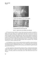
Figure 1.2: Partial collapse of Ronan Point Apartment (Griffiths et al., 1968) 28
Figure 1.3: Partial collapse of Alfred P. Murrah Building (Hinman and Hammond, 1997)
28
Figure 1.4: Aircraft entry hole on the north side of WTC1, 30s after impact (NIST, 2005)
29
Figure 2.1: Simplified truss models by Hill et al. (1989) and CSA (1984) 57
Figure 2.2: Proposed beam-column model for progressive collapse analysis of steel frames
57
Figure 2.3: Second-order effects in sway and non-sway columns 58
Figure 2.4: Fiber sections for common steel shapes 58
Figure 2.5: Influence of plastic zone length (
L
p
) on buckling response 59
Figure 2.6: Influence of element length within plastic zone on buckling response 60
Figure 2.7: Influence of number of fibers at monitored locations on buckling response 61
Figure 2.8: Residual stress profile recommended by European Convention for
Constructional Steelwork (ECCS, 1983) 62
Figure 2.9: Influence of residual stress on column buckling response 62
Figure 2.10: Influence of out-of-straightness (
e
0
)
on buckling response 63
Figure 2.11: Membrane action of unrestrained slab at large out-of-plane deformation 64
Figure 2.12: Composite slab comprises of profiled deck and reinforced concrete slab 64
Figure 2.13: Proposed composite slab model based on modified grillage method 65
vi
Figure 2.14: Uniaxial stress-strain relationship of concrete material according to Eurocode
2 (BSI, 2004a) 66
Figure 2.15: Membrane action of unrestrained pin-ended truss system at large out-of-
plane deformation 66
Figure 2.16: In-plane shear deformation of concrete panel and the equivalent truss system
66
Figure 2.17: Component model for fin plate shear connection proposed by Sadek et al.
(2008) 67
Figure 2.18: Spring properties of component model proposed by Sadek et al. (2008) 67
Figure 3.1: Buckling capacities of 72 columns consist of different shapes and boundary
conditions: Comparison between Eurocode 3 (BSI, 2005a) and the present study 98
Figure 3.2: Cyclic post-buckling response of column consists of different shapes,
slenderness and boundary conditions: Comparison between the present study and
experiment by Jain et al. (1978) and Black et al. (1980) 99
Figure 3.3: Compression envelope of post-buckling response of wide-flange column
consists of different slenderness and boundary conditions: Comparison between the
present study, Opensees (McKenna et al., 2006) and experiment by Black et al. (1980)
100
Figure 3.4: Compression envelope of post-buckling response of box column consists of
different slenderness and boundary conditions: Comparison between the present study,
Opensees (McKenna et al., 2006) and experiment by Jain et al. (1978) 101
Figure 3.5: Static response of two-bar truss under gravity load: Comparison between the
present study and numerical study by Liew et al. (1997) 102
Figure 3.6: Static response of star dome under gravity load (case 1): Comparison between
the present study and numerical study by Liew et al. (1997) 103
Figure 3.7: Static response of star dome under gravity load (case 2): Comparison between
the present study and numerical study by Blandford (1996) 104
Figure 3.8: Progressive collapse sequence of star dome under point load at crown node
(case 2) 105
vii
Figure 3.9: Geometries of circular dome and geodesic dome 105
Figure 3.10: Static response of circular dome under gravity load: Comparison between the
present study and numerical study by Thai and Kim (2009) 106
Figure 3.11: Static response of geodesic dome under gravity load: Comparison between
the present study and numerical study by Thai and Kim (2009) 106
Figure 3.12: Static response of single-storey 2D frame under gravity and lateral loads:
Comparison between present study and numerical study by Vogel (1985) 107
Figure 3.13: Static response of six-storey 2D frame under gravity and lateral loads:
Comparison between present study and numerical study by Vogel (1985) 107
Figure 3.14: Static response of six-storey 3D building under gravity and lateral loads:
Comparison between the present study and numerical study by Jiang et al. (2002) 108
Figure 3.15: Static response of twenty-storey 3D building under gravity and lateral loads:
Comparison between the present study and numerical study by Liew et al. (2001) 109
Figure 3.16: Cases of column removal considered for two-storey moment frames studied
by Kaewkulchai and Williamson (2004) 110
Figure 3.17: Dynamic response of two-storey moment frame due to sudden column
removal: Comparison between the present study and numerical study by Kaewkulchai
and Williamson (2004) 110
Figure 3.18: Cases of column removal considered for three-storey moment frame studied
by Kaewkulchai and Williamson (2004) 111
Figure 3.19: Dynamic response of three-storey moment frame due to sudden column
removal: Comparison between the present study and numerical study by Kaewkulchai
and Williamson (2004) 111
Figure 3.20: Static response of a reinforced concrete slab under gravity load: Comparison
between the present study and experiment by Jofriet and McNeice (1971) 112
Figure 3.21: Static response of a composite slab strip under 2-point loads in gravity
direction: Comparison between the present study and experiment by Abdullah and
Easterling (2009) 113
viii
Figure 3.22: Static response of a large ribbed reinforced concrete slab under uniform area
load in gravity direction: Comparison between the present study, experiment by Bailey et
al. (2000), and detailed finite element analysis by Elghazouli and Izzuddin (2004) 114
Figure 3.23: Configuration of fin plate shear connection studied by Sadek et al. (2008) 114
Figure 3.24: Static response of fin plate shear connection under point load: Comparison
between the present study and numerical study by Sadek et al. (2008) 115
Figure 4.1: Floor layout of the NIST prototype building, area of floor system studied
(hatched) and location of internal column removal 134
Figure 4.2: Various fin plate connections considered in the study of NIST floor system 134
Figure 4.3: Numerical model of NIST floor system used in the study 135
Figure 4.4: Collapse resistance of NIST floor due to internal column removal for various
methods of slab modeling: Comparison between the presented method and detailed FEA
by Alashker et al. (2010) 135
Figure 4.5: Collapse resistance of NIST floor due to internal column removal for various
deck thicknesses: Comparison between the presented method and detailed FEA by
Alashker et al. (2010) 136
Figure 4.6: Collapse resistance of NIST floor due to internal column removal for various
slab reinforcement densities: Comparison between the presented method and detailed
FEA by Alashker et al. (2010) 137
Figure 4.7: Collapse resistance of NIST floor due to internal column removal for various
connection designs: Comparison between the presented method and detailed FEA by
Alashker et al. (2010) 138
Figure 4.8: Influence of deck thickness on collapse resistance of NIST floor 139
Figure 4.9: Influence of reinforcement density on collapse resistance of NIST floor 139
Figure 4.10: Influence of connection design on collapse resistance of NIST floor 140
Figure 4.11: Layout of the UCB floor and location of perimeter column removal 141
Figure 4.12: Numerical model of UCB test floor system used in the study 141
ix
Figure 4.13: Collapse resistance of UCB test floor due to perimeter column removal:
Comparison between the presented method, detailed FEA by Yu et al. (2010) and
experiment by Tan and Astaneh-asl (2003) 142
Figure 4.14: Influence of the connection design on static and dynamic collapse resistances
of UCB test floor 143
Figure 5.1: Floor layout of Cardington building and 2D frame studied (hatched region)
168
Figure 5.2: Numerical model of 8-storey Cardington 2D frame 168
Figure 5.3: Fiber sections of steel beam and composite slab 169
Figure 5.4: Modeling of belt truss system (imperfection exaggerated) 169
Figure 5.5: Equivalent static load due to sudden column removal 169
Figure 5.6: Displacement time-history due to sudden removal of column D1 of 2D frame
170
Figure 5.7: Load-displacement relationships of 2D frame with different types of belt truss
(BT) system 171
Figure 5.8: Influence of the brace strength on displacement demand of 2D frame 172
Figure 5.9: Influence of the brace strength on global force demand of 2D frame 172
Figure 5.10: Influence of the brace strength on column (LC) force of 2D frame 173
Figure 5.11: Uneven column force in 2D frame caused by N-brace belt truss 173
Figure 5.12: Deformed shapes and truss actions of various belt truss systems 174
Figure 5.13: Influence of the belt truss (BT) position on column force demand of 8-storey
Cardington 2D frame 175
Figure 5.14: Influence of the number and position of belt truss on column force demand
of 20-storey Cardington 2D frame 176
Figure 5.15: Influence of the belt truss position on column force demand of 20-storey
Cardington 2D frame 177
x
Figure 5.16: Natural frequencies and corresponding vibration modes of Cardington floor
structure: Comparison between the presented method and detailed FEA by El-Dardiry
and Ji (2006) 178
Figure 5.17: Column forces of 3D Cardington building: sudden removal of storey 1
perimeter column D1 (Case 1) 179
Figure 5.18: Column forces of 3D Cardington building: sudden removal of storey 1 corner
column A1 (Case 2) 180
Figure 5.19: Column forces of 3D Cardington building: sudden removal of storey 4 corner
column A1 (Case 3) 181
Figure 6.1: Dynamic response of simple frame due to sudden column removal 192
Figure 6.2: States of energy balance for simple frame and corresponding capacity curve
193
Figure 6.3: Displacement time-history and capacity curve of UCB floor (3x1 fin plate
connection) due to sudden column removal: Comparison between equivalent static
analysis (ESA) and nonlinear time-history (NLTH) methods 194
Figure 6.4: Displacement time-history and capacity curve of UCB floor (5x1 fin plate
connection) due to \sudden" column removal: Comparison between equivalent static
analysis (ESA) and nonlinear time-history (NLTH) methods 195
Figure 6.5: Influence of connection design on capacity of UCB floor under sudden column
removal 196
Figure 6.6: Load-displacement relationships of 2D frame with K-brace belt truss of
varying strength 196
Figure 6.7: Load-displacement relationships of 2D frame with N-brace belt truss of
varying strength 197
Figure 6.8: Load-displacement relationships of 2D frame with X-brace belt truss of
varying strength 197
Figure 6.9: Accuracy of equivalent static analysis (ESA) in estimation of global
displacement demand 198
xi
Figure 6.10: Accuracy of equivalent static analysis (ESA) in estimation of global force
demand 199
Figure 6.11: Accuracy of equivalent static analysis (ESA) in estimation of column force
demand 200
Figure 6.12: Static response of Cardington building due to perimeter and corner column
removal 201
Figure 6.13: Accuracy of equivalent static analysis (ESA) in estimation of column force
(Case 1) 202
This page intentionally left blank
xii
List of Tables
Table 1.1: Rotational capacities of partially-restrained steel connections (GSA, 2003) 26
Table 2.1: Influence of plastic zone length (
L
p
) on buckling and post-buckling responses of
column 55
Table 2.2: Influence of element length on buckling and post-buckling responses of column
56
Table 3.1: Comparison of column buckling capacities obtained from the present study
and Eurocode 3 (BSI, 2005a) 94
Table 3.2: Column specimens tested by Jain et al (1978) and Black et al. (1980) 95
Table 3.3: Member properties of two-storey and three-storey moment frames studied by
Kaewkulchai and Williamson (2004) 96
Table 3.4: Reaction forces used for simulating sudden column removal of two-storey and
three-storey moment frames studied by Kaewkulchai and Williamson (2004) 96
Table 3.5: Summary of numerical examples considered in the verification study 97
Table 4.1: Collapse resistance of NIST floor due to internal column removal for varying
deck thicknesses, slab reinforcement densities and connection designs: Comparison
between detailed FEA by Alashker et al. (2010) and the presented method 132
Table 4.2: Contribution of steel deck to collapse resistance of NIST floor 132
Table 4.3: Contribution of slab reinforcement to collapse resistance of NIST floor 133
Table 4.4: Contribution of connection to collapse resistance of NIST floor 133
Table 5.1: Properties of belt truss used in the study of 8-storey Cardington 2D frame . 165
Table 5.2: Properties of belt truss used in the study of 20-storey Cardington 2D frame 165
Table 5.3: Displacement demands of 20-storey Cardington 2D frame when subjected to
sudden column removal: Influence of number and position of belt truss 166
xiii
Table 5.4: Natural frequencies of Cardington floor: Comparison between the presented
method, detailed FEA by El-Dardiry et al. (2006) and Insitu test by Ellis et al. (1996) 166
Table 5.5: Displacement and global force demands of Cardington 3D building when
subjected to different cases of sudden column removal 167
Table 6.1: Displacement and global force demands of Cardington 3D building when
subjected to different cases of \sudden" column removal: Comparison between nonlinear
time-history analysis (NLTH) and ESA prediction 191
xiv
List of Symbols
For ease of reference, the definition of commonly used symbols and notations are listed
below.
Acronyms
AISC
American Institute of Steel Construction
ALP
Alternate load path
DAC
Double angle cleat
DL
Dead load
DoD
Department of Defense, USA
EC3
Eurocode 3 (BSI, 2005a)
FEA
Finite element analysis
FEMA
Federal Emergency Management Agency, USA
FP
Fin plate
GSA
General Services Administration, USA
LL
Live load
MHA
Ministry of Home Affairs, Singapore
NIST
National Institute of Science and Technology, USA
BT
Belt truss system
OS
Open System for Earthquake Engineering Simulation (OPENSEES)
SAP
Structural Analysis Program (SAP2000) (CSI, 2009)
SDL
Superimposed dead load
SCI
Steel Construction Institute, UK
SDOF
Single degree of freedom
SL
Snow load
xv
UDL
Uniformly distributed load
WL
Wind load
WTC
World Trade Centre, New York City
IStructE
Institution of Structural Engineers, UK
Roman Symbols
i
A
area of the i
th
fiber of a fiber section
1
B
spacing of grillage in direction of steel deck
2
B
spacing of grillage in direction perpendicular to steel deck
1
C
web thickness of the equivalent T-section grillage member
d
nominal bolt diameter
1
d
distance from top of slab to center of reinforcement mesh
bg
d
vertical depth of the bolt-group of a connection
i
d
distance of the i
th
fiber to centroid
0
e
magnitude of initial crookedness of a frame
i
E
elastic modulus of the i
th
fiber
EA
axial rigidity of a frame section
EI
flexural rigidity of a frame section
s
E
elastic modulus of steel material
c
E
elastic modulus of concrete material
c
f
concrete crushing strength
y
f
steel yielding strength
,
yj
F
yield capacity of spring representing j
th
bolt-row of connection
xvi
,
uj
F
ultimate capacity of spring representing j
th
bolt-row of connection
c
h
height of concrete above the steel deck of composite slab
d
h
height of steel deck of composite slab
n
R
tear-out resistance of bolt-row on connection
t
thickness of connected material of fin plate connection
k
initial rotational stiffness of connection without contribution of floor slab
,bj
k
initial axial stiffness of spring representing j
th
bolt-row of connection
L
length of a frame member
c
L
clear distance between edge of bolt and edge of material
p
L
total length of plastic zone along a frame member
m
total number of fiber throughout a section
n
total number of bolt in the bolt-group of a connection
1
n
number of layer along flange or web plate of a steel section
2
n
number of layer across thickness of web or flange plate of a steel section
r
radius of gyration for calculation of member slenderness
j
s
distance from center of bolt group to the j
th
bolt-row
max
s
distance from center of the bolt group to the most distant bolt
d
t
thickness of steel deck
w
uniformly distributed load on frame member
Greek Symbols
δ
displacement along a frame in second-order analysis
Δ
end displacement of a frame in second-order analysis