Design and synthesis of functional graphene composites and their applications
Bạn đang xem bản rút gọn của tài liệu. Xem và tải ngay bản đầy đủ của tài liệu tại đây (11.21 MB, 156 trang )
DESIGN AND SYNTHESIS OF FUNCTIONAL
GRAPHENE COMPOSITES AND THEIR APPLICATIONS
JANARDHAN BALAPANURU
NATIONAL UNIVERSITY OF SINGAPORE
2013
I | P a g e
DESIGN AND SYNTHESIS OF FUNCTIONAL
GRAPHENE COMPOSITES AND THEIR APPLICATIONS
JANARDHAN BALAPANURU
M.Sc., University of Pune, India.
A THESIS SUBMITTED
FOR
THE DEGREE OF DOCTOR OF PHILOSOPHY
DEPARTMENT OF CHEMISTRY
NATIONAL UNIVERSITY OF SINGAPORE
2013
II | P a g e
Declaration
I, hereby declare that this thesis is my original work and it has been written by
me in its entirety, under the supervision of Prof. Loh Kian Ping at Department of Chemistry,
National University of Singapore, during Jan’ 2009 to Aug’ 2013. I have duly acknowledged
all the sources of information used for this thesis. This thesis has not been submitted for any
degree at any other University.
JANARDHAN BALAPANURU 6
th
May 2014
Name Signature Date
III | P a g e
Dedication
A Humble Offering at
The Lotus Feet of
My Guru
Bhagawan Sri Satya Sai Baba
IV | P a g e
Acknowledgements
This dissertation would not have been possible without the help of so many people in
so many ways. First and foremost, I sincerely thank my supervisor Prof. Loh Kian Ping for
his scientific guidance and moral support. Especially, his efforts in correcting this thesis
should be mentioned. I could not have imagined a better mentor than him. His passion to do
good Science and publish high-impact journals inspires me to set a high standard for myself.
Almost 5 years of regular contact with him has a huge positive impact on shaping my
thinking and attitude towards research.
Next, I greatly acknowledge the help from our collaborators: Prof. Ji Wei, Assoc.
Prof. Xu Qing-Hua and their group members (Dr. Laxminarayana Polavarapu and Ms. Zhou
Na) for the nonlinear optics, pump-probe experiments and hydrogen detection studies.
Special thanks to Dr. Srinivasulu Bellum, Dr. Jia-Xiang Yang and Dr. Su Chenliang,
whose training and suggestions always helped me to succeed in my research projects. All the
other lab members Dr. Bao Qiaoliang, Dr. Xiao Si, Anupam, Kiran, Lena Tang, Divya
Manilal, Maryam Jahan, Goh Beemin, Ananya, Zhaomeng, Chang Tai, Xiao Fen, Pricilla,
Alison, Yan Peng, Tang Wei, Dr. Dong, Dr. Peng, Liu Wei and Song Peng are always there
to help me. Joyful moments with my buddies Rama, Ashok, Raghava, Vamsi, Kiran Amara,
Gopal, Vasu and Venu are still in my fresh memories.
Words are not enough to thank my parents whose unconditional love and care always
inspire me to be kind and patient. Here, I wish to express my gratitude to my spiritual master
“Sri Satya Sai Baba” who made it happen and whose grace always guide me to face all the
difficulties in this journey of life. Lastly, I thank NUSNNI graduate programme for
supporting this doctorial studies in Singapore. Thank you one and all!
V | P a g e
Publications
1. Janardhan Balapanuru, Jia-Xiang Yang, Si Xiao, Qiaoliang Bao, Maryam Jahan,
Lakshminarayana Polavarapu, Qing- Hua Xu, Ji Wei, Kian Ping Loh “A Graphene Oxide-
Organic Dye Ionic Complex with DNA Sensing and Optical Limiting
Properties”, Angewandte Chemie, 2010, 49, 6549-6553.
(Highlighted by Nature Asia Materials)
Graphene devices: Complex combo: NPG Asia Mater 3: 8; doi:10.1038/asiamat.2010.168.
2. Venkatesh Mamidala, Lakshminarayana Polavarapu, Janardhan Balapanuru, Kian Ping
Loh, Wei Ji, and Qing-Hua Xu, “Enhanced Nonlinear Optical response in Donor-Acceptor
complexes via Photo induced Electron/Energy Transfer” Optics express, 2010, 18, 25928.
3. Lakshminarayana. Polavarapu, Kiran Kumar Manga, Yu Kuai, Priscilla Kailian Ang, Cao
Hanh Duyen, Janardhan Balapanuru, Kian Ping Loh, Qing-Hua Xu. “Alkylamine Capped
Metal Nanoparticle “Inks” for Printable SERS Substrates, Electronics and Broadband
Photon Detectors” Nanoscale, 2011, 3, 2268.
4. Janardhan Balapanuru, Kian Ping Loh, “ Graphene-based Photoactive PDI-Co complex
for Photoelectrochemical Water Splitting” (under revision )
5. Su Chenliang, Janardhan Balapanuru, Kian Ping Loh “Graphene Oxide-supported Pd
hybrid: An Efficient Bi-functional Catalyst for Cascade Oxygen and Hydrogen Activation”
(to be submitted soon)
VI | P a g e
TABLE OF CONTENTS
Declaration II
Dedication III
Acknowledgements IV
Publications V
Table of Contents VI
Summary XII
List of Tables XIV
List of Figures XV
List of Schemes XXII
List of Abbreviations XXII
Table of Contents
Chapter 1: Introduction 1-28
1.1. Introduction and properties of Graphene 1
1.2. Chemically Converted Graphene (CCG) 2
1.2.1. Preparation
1.2.2. Structure
1.3. Graphene- based Composites 6
1.3.1. A brief overview 6
1.3.2. Preparation – General Strategies 6
1.3.2.1 Covalent Functionalization 6
1.3.2.2. Non-covalent Functionalization 8
1.3.3. Composites with Small organic molecules 10
1.3.4. Composites with Polymers 11
VII | P a g e
1.3.5. Composites with Metal Nanoparticles (MNPs) 13
1.4. Applications of Graphene-based Composites 14
1.4.1. Optical Sensing ………… 14
1.4.2. Non-linear optical limiting properties 15
1.4.3. Photo-electrochemical watersplitting- Hydrogen Evolution Reaction (HER) 16
1.4.4. Metal-free Oxygen Reduction reaction (ORR) 18
1.4.5. Carbocatalysis 19
1.5. Objectives and Scope of the current work………………….……………….…….21
1.6. References 24
Chapter 2: Experimental Techniques 29-37
2.1. Introduction 29
2.2. Nuclear Magnetic Resonance (NMR) Spectroscopy………… 29
2.3. Matrix-Assisted Laser Desorption/Ionization Time-of-Flight (MALDI-TOF)………31
2.4. Single Crystal XRD Studies……… 32
2.5. UV-Vis absorbance Spectroscopy………………………………………….… 33
2.6. Atomic Force Microscopy (AFM) ……………………………………… 34
2.7. X-ray Photoelectron Spectroscopy (XPS)…………………………… 35
2.8. Thermo Gravimetric Analysis (TGA)………………………………… 36
2.9. References 37
Chapter 3: A Graphene oxide/Organic dye Ionic Complex with DNA-
sensing and Optical-limiting properties 38-63
3.1. Introduction 39
3.2. Materials and Methods 39
3.2.1. Synthesis of Graphene Oxide …………………… 41
3.2.2. Synthesis of PNPB Dye ………………………………………… 42
VIII | P a g e
3.2.3. X-ray crystal structure determination of PNPB 43
3.2.4. Synthesis of PNP
+
GO
-
Complex 45
3.3. Result and discussion 46
3.3.1. Synthetic Strategy: Ion Exchange Method 46
3.3.2. FT-IR Studies 47
3.3.3. AFM Characterization 48
3.3.4. UV-Vis Spectroscopic Studies 49
3.3.5. Fluorescence Studies 50
3.3.6. Surfactants – Fluorescence enhancing ability 51
3.3.7. Biomolecules – Fluorescence enhancing ability and DNA selectivity 52
3.3.8. Control studies: Effect of the concentration of GO on PNP
+
DNA
–
hybrid 54
3.3.9. Quantitative Calibration of DNA with PNP
+
GO
-
complex 55
3.3.10. Non-linear Optical limiting Properties 56
3.3.11. Charge-transfer Dynamics 59
3.4. Conclusion 60
3.5. References 61
Chapter 4: Photoactive PDI-Cobalt Complex immobilized on Reduced-
Graphene Oxide for Photoelectrochemical Water Splitting. 64-86
4.1 Introduction 65
4.2. Results and discussion…………………………………………………………… 66
4.3. Conclusions………………………………………………………………………… 73
4.4. References …………………………………………………………………….… 74
4.5. Supporting Information……………………………………………………….….….77
S1.1. Synthesis of Graphene Oxide (GO)………………………………………… 78
S1.2. Synthesis of reduced Graphene Oxide (rGO)………………………………….78
IX | P a g e
S1 Synthesis of Perylene tetracarboxylic Di-(propyl Imidazole) (PDI)………… 79
S1.4. Bandgap calculations………………………………………………………….79
S1.5. Synthesis of Co-ordination polymer [PDI-Co-Cl2(H2O)2]n or PDI-Co…….80
S1.6. Fourier Transform Infrared Spectroscopy (FTIR) studies……………….……81
S1.7. SEM and Energy-dispersive X-ray spectroscopy (EDS) Mapping……….… 82
S1.8. Thermo gravimetric analysis……………………………………………….….83
S1.9. Estimation of active Cobalt concentration in rGO:PDI-Co (ratio 0.4:1)… …84
S1.10. Calculation of turnover number (TON vs CoII )………………………….…85
S1.11. References……………………………………………………………… … 86
Chapter 5: Graphene Oxide-supported Pd: An Efficient Bi-functional
Catalyst for Cascade Oxygen and Hydrogen Activation reactions. 87-117
5.1. Introduction 88
5.2. Materials and Methods 89
5.2.1. Synthesis of Graphene Oxide (GO)……………………………………….… 90
5.2.2. Synthesis of base-acid treated GO or baGO………………………….… …91
5.2.3. Synthesis of baGO/Pd hybrid……………………………………………… 91
5.2.4. One-pot cascade oxygen and hydrogen activation reactions………………… 92
5.3. Results and discussion 92
5.3.1. Importance of base-acid treatment of GO …………………………….…… 93
5.3.2. Catalytic performance of baGO and baGO/Pd hybrid ……………….… … 95
5.3.2.1. Catalytic performance of baGO…………………………….… … 95
5.3.2.2. baGO/Pd hybrid as a bifunctional catalyst……………………… 96
5.3.2.3. Catalytic performance of baGO/Pd……………………………… 97
5.3.2.3. Characterizations of baGO/Pd ………………………………… ….99
5.3.2.4. GC/MS Spectral Analysis……………………………… …… ….102
5.3.2.5. Controlled experiments with different catalysts………………… 103
X | P a g e
5.3.2.5. Scope of reaction with baGO/Pd for different substrates…… … 105
5.4. Conclusions 106
5.5. References 107
Chapter 6: Graphene-based Poly-(Imidazolium ionic Liquid) Complex for
Metal-Free Oxygen Reduction Reaction 108-125
6.1. Introduction …………………………………………………………………… 109
6.2. Experimental Section…………………………………………………………… 110
6.2.1. Chemicals and materials………………………………………………… …110
6.2.2. Characterizations and electrochemical measurements…………………… 110
6.2.3. Synthesis of Graphene Oxide (GO)……………………………………… 111
6.2.4. Synthesis of Imidazolium Ionic liquid (ImIL) …………………………….112
6.2.5. Synthesis of Poly(Imidazolium Ionic liquid) (PImIL) ………………… 112
6.2.6. Synthesis of reduced-graphene oxide (rGO)……………………………….113
6.2.7. Synthesis of rGO-PImIL complex……………………………………… 114
6.3. Results and discussion……………………………………………………………115
6.3.1. Characterizations of PImIL and rGO- PImIL…………………………….115
6.3.1.1. UV/Vis Spectroscopy studies……………………………………115
6.3.1.2. Fourier Transform Infrared Spectroscopy (FTIR) studies……….116
6.3.1.3. X-ray photoelectron spectroscopic(XPS) studies……………… 117
6.3.2. Electrochemical Oxygen reduction reaction (ORR)……………………….119
6.3.2.1. Cyclic Voltametry (CV) studies- ORR performance……………119
6.3.2.2. Rotating disk electrode (RDE)-
Linear sweep voltammetric (LSV)studies……….…120
6.3.2.3. Kinetics of ORR: Koutecky- Levich ( K-L ) plots 121
6.4. Conclusions………………………………………………………………………123
6.5. References……………………………………………………………………….124
XI | P a g e
Chapter 7: Conclusions and Future outlook 126-129
7.1. Challenges and Future outlook 128
7.2. References 129
APPENDIX 130
XII | P a g e
SUMMARY
Recently, graphene has attracted tremendous interests from the scientific and
industrial communities owing to its exceptional properties. Chemical exfoliation of graphite
to produce graphene derivatives such as graphene oxide (GO) and reduced graphene
oxide (rGO) offers a wide range of possibilities to develop functional graphene composites
for various applications. In this thesis, the design and synthesis of various graphene-based
composites and their potential applications have been discussed with regards to four different
hybrid systems: (i) fluorescent dye (ii) poly-(ionic liquids) (iii) dye-metal complex and
(iv) metal nanoparticles. Firstly, as detailed in Chapter 3, a charge-transfer complex between
GO and a pyrene dye has been synthesized via a simple ion-exchange process. Its highly
specific interactions with DNA compared to other bio-molecules allow selective and rapid
detection of DNA in biological mixtures. In addition, this GO–dye complex exhibits unique
broadband optical limiting properties.
Inspired by the charge-transfer abilities of GO, we report in Chapter 4, a
graphene-based photoactive dye-metal complex for photoelectrochemical water-splitting to
produce hydrogen
fuel. To meet the requirement, a photoactive perylene derivative (PDI) has
been coupled to cobalt(II) ions to form a co-ordination polymer (PDI-Co), which is later
immobilized on rGO via non-covalent interactions. Here, rGO has been used as the scaffold
and electron-transfer mediator to enhance the photo-driven hydrogen evolution at Co(II)
center. Compared to commercial TiO
2
catalyst supported on rGO, the rGO-PDI-Co complex
shows better response.
To address the poor solubility and irreversible agglomeration issues faced by rGO, we
developed a poly-imidazolium ionic liquid (PImIL) coupled rGO complex (rGO-PImIL) and
XIII | P a g e
presented the work in Chapter 5. The co-operative ionic and π-π interactions between rGO
and PImIL improve the solubility of rGO-PImIL in ethanol compared to pure rGO.
Furthermore, we have explored the use of rGO-PImIL as a metal-free catalyst for oxygen
reduction reaction (ORR). The results show that ORR at rGO-PImIL occurs via a facile 4e
¯
transfer process similar to that of platinum-based catalysts, whereas 2e
¯
path way is observed
for bare rGO.
Finally, to explore the catalytic abilities of graphene composites, we have developed a
GO-supported Pd nanoparticle bifunctional catalyst for one-pot cascade oxygen and hydrogen
activation reactions to produce secondary amines by N-alkylation of primary amines (Chapter
6). The synergetic effect of the GO and Pd nanoparticles enable the GO/Pd hybrid catalyst to
work under milder conditions (open air and 1 atm H
2
) compared to previously reported
catalysts.
In summary, regardless of the chemical composition of the hybrid system, the addition
of GO or rGO imparts additional functionalities and improves the performance of the system.
XIV | P a g e
List of Tables
Table
Description
Page
Table 1.1
Comparison of typical synthetic methods for graphene–inorganic
nanostructure composites and their related applications
21
Table 3.1
Crystal data and refinement parameters for PNPB
43
Table 3.2.
Selected Bond lengths [Å] and Angles [] for PNPB
45
Table 5.1
Inductively coupled mass spectrometry (ICP-MS) analysis
[1]
93
Table 5.2.
One-pot cascade reaction to form dibenzylamine from
bezylamine which involves sequential O
2
and H
2
activation. The
yields obtained using different catalysts are displayed below
97
Table 5.3
One-pot cascade O
2
and H
2
activation reactions to form
dibenzylamine from benzylamine using different catalysts.
102
Table 5.4
Scope of reaction with baGO/Pd hybrid catalyst for different
substrates
104
XV | P a g e
List of Figures
Figure
Description
Page
Figure 1.1
Graphene being the basic building block of all graphitic materials
namely Fullerenes (C
60
), CNT and 3D graphite.
[5]
2
Figure 1.2
Preparation of chemical converted graphene(CCG) by reduction of
graphene oxide.
[10]
3
Figure 1.3
(a) Preparation of GO. (b) Proposed structure of GO based on the
Lerf- Klinowski model. Hydroxyls and epoxide-groups (pink) are the
dominant functionalities on the basal plane. The edge defects are
unique sites for some oxygen functionalities (blue), which are not
found on the basal planes. (c) HR-TEM spectrum of GO.
[1, 20]
4
Figure 1.4
HR-TEM image
[22]
of single layer CCG derived from the graphene
oxide prepared by Hammers’ method
[10]
5
Figure 1.5
Covalent functionalization of CCG via diazonium coupling
reaction.
[29]
7
Figure 1.6
Covalent modification of CCG by using carboxyl groups (a) and
epoxy groups
[32]
(b) of partially reduced GO
[34]
8
Figure 1.7
Non-covalent functionalization of CCG via electrostatic interactions
(a) CCG-PEDOT
[36]
(b) CCG-Peptide composite
[35]
9
Figure 1.8
π-π interactions between PEG-OPE and CCG or rGO
[39]
10
Figure 1.9
(a) Formation of CCG- TMPyPcomposite and its performance as
optical probe Cd
+2
detection
[40]
and (b) Formation of CCG-PDI nano
wires and its solar cell performance.
[41]
11
Figure 1.10
(I) Fabrication and solubility test of CCG- PFVSO
3
[42]
and (II)
CCG-PANI composite and its electrochemical performance.
[45]
12
Figure 1.11
Illustration of preparation for CCG/MNP composite via solution
mixing with the assistance of bovine serum albumin (BSA) and TEM
images of typical CCG/MNP composites
[10]
13
Figure 1.12
(a) CCG based platform for thrombin detection
[50]
and (b) GO based
platform for pathogen sensing
[51]
15
Figure 1.13
(a) Photo induced energy transfer mechanism between
oligothiophene(6THIOP) and GO (b) Fluoroscence quenching ability
of GO (c) non-linear optical properties of GO-6THIOP
[52]
16
Figure 1.14
Photo-electrochemical hydrogen evolution of (a) rGO-BiVO
4
[58]
and
(b) rGO/EY/Pt
[59]
17
Figure 1.15
(a) Graphite-ball milled composite and its ORR performance (b)
rGO-PDDA composite and its ORR performance.
[61]
18
Figure 1.16
Catalytic comparison among CCG/Pd, GO/Pd and Pd/C.
[64]
19
XVI | P a g e
Figure 2.1
1
H NMR correlation between Chemical Shift and type of H in
functional groups. (Reproduced from Ref.[1] )
30
Figure 2.2
A simple correlation between Chemical Shift and type of C atom
(Reproduced from Ref.[1] )
31
Figure 2.3
Schematic illustration of MALDI-TOF working principle
(Reproduced from Ref.[2] )
31
Figure 2.4
Schematic of 4-circle diffractometre and the actual experimental set-
up. (Reproduced from Ref.[4] )
32
Figure 2.5
Schematic illustration of UV-Vis Spectrometer and energy level
diagram (Reproduced from Ref.[5] )
33
Figure 2.6
Schematic illustration of AFM. (Reproduced from Ref. [7])
34
Figure 2.7
Schematic illustration of X-ray photoelectron spectroscopy.
(Reproduced from Ref.[9] )
35
Figure 2.8
Schematic illustration of TGA and a typical TGA spectrum.
(Reproduced from Ref.[9])
36
Figure 3.1
Crystal structure of PNPB
44
Figure 3.2
FT-IR spectra of (a) GO (b) PNPB (c) PNP
+
GO
-
47
Figure 3.3
The atomic force microscopy spectrum of (a) GO and (b) PNP
+
GO
-
48
Figure 3.4
(a) UV/Vis absorption spectra of aqueous solutions of PNP
+
GO
-
(~20
mgL
-1
), PNPB (2×10⁻⁶ M), GO(~34 mgL
-1
) (b) Concentration-
dependent UV/Vis absorption spectra of PNP+GO- (from 11.2 mgL
-1
to 25.2 mgL
-1
(a-h) respectively), inset shown is the plot of optical
density at 238 nm versus concentration (mg L
-1
).
49
Figure 3.5
Fluorescence spectra of PNP
+
GO
-
(~ 20 mg L
-1
) and PNPB (2 × 10
-6
M)
50
Figure 3.6
Comparative fluorescence intensities of PNP
+
GO
-
(10 mg L
-1
)
complexed with different surfactants at equal concentration of 1 mM
and their fluorescence under UV light (inset).
51
Figure 3.7
a) Fluorescence spectra and b) comparative intensities of PNP
+
GO
-
(10 mgL
-1
) complexed with DNA, RNA, proteins (BSA, heme, BLP,
CTA), and glucose at equal concentrations of 20 μm.
52
Figure 3.8
(A) Fluorescence spectra of DNA(20μM)/PNP
+
(2×10
-6
M) hybrid
with different amounts of GO ranging from 0 to 30 mgL
-1
. (B) Image
of PNP
+
DNA
-
hybrid mixed with GO of (a) 0 mgL
-1
(b) 5 mgL
-1
(c)
10 mgL
-1
(d) 15 mgL
-1
(e) 20 mgL
-1
(f) 25 mgL
-1
(g) 30 mgL
-1
and (h)
35 mgL
-1
, under UV light.
54
Figure 3.9
a) Fluorescence spectra of PNP
+
GO
-
complexed with different
concentrations of DNA ranging from 10 to 400 nm b) Calibration plot
55
XVII | P a g e
of fluorescence intensity at 580 nm versus concentration of DNA
[nM]. The inset shows the calibration plot at low concentrations of
DNA (up to 50 nm). c) Image of PNP
+
GO
-
complexed with different
concentrations of DNA under UV light.
Figure 3.10
Optical limiting response of aqueous solutions of PNP
+
GO
-
(20 mgL
-
1
), GO (34 mg
-1
), and PNPB (2 ×10
-6
M), measured with 7 ns laser
pulses at a) 532 and b) 1064 nm. Nonlinear scattering response of
PNP
+
GO
-
, GO and PNPB solutions at laser pulses of 532(c and e) and
1064 nm (d and f), where c) and d) show intensity-dependent
scattering signals at 532 and 1064 nm, respectively, and e) and f)
angle-dependent scattering signals at 532 and 1064 nm respectively.
57
Figure 3.11
Normalized transient absorption of PNPB and PNP
+
GO
-
aqueous
solutions monitored at 530 nm with a pulse energy of 20nJ/pulse. The
solid lines shown are the best fit with multi exponential function after
deconvolution.
59
Figure 4.1.
Sysnthetic route for the coupling PDI to CoCl2 to form “PDI-Co”
polymer. (a) PDI in CHCl3 (b) Separation of CoCl2.6 H2O solution
on the top of PDI solution (color changed due to diffusion of CoCl2)
and (c) After 4 h of heating, formation of “PDI-Co” polymer
precipitate. (In set- SEM image of final product)
67
Figure 4.2
UV-Vis absorption Spectra of PDI and PDI-Co and rGO-PDI-Co
suspensions in DMF/ethanol mixture. (a) Comparison between PDI
and PDI-Co (b) Comparison between PDI-Co, rGO and rGO-PDI-Co.
68
Figure 4.3
(a) Cyclic voltammogram(CV)s of (i) PDI-Co (ii) rGO:PDI-Co
(0.2:1) (iii) rGO:PDI-Co (0.4:1) and (iv) rGO:PDI-Co (0.8:1); all
voltammograms were measured in dry acetonitrile (0.1 M
nBu
4
N
+
PF
6
-
) at a scan rate of 10 mV.s
-1
. (b) Active cobalt mass
comparison among various composites of rGO/PDI-Co and (c)
comparative CV plots of PDI, PDI-Co and rGO-PDI-Co.
69
(Under Chapter 4)
Figure S1.
Scanning electron microscopic (SEM) images of PDI. Higher
magnification (right)
79
Figure S2.
Frontier orbitals of PDI calculated using DFT at the B3LYP/6-31G*
80
Figure S3.
Comparative FITR Spectra of PDI, PDI-Co, rGO and rGO-PDI-Co
81
Figure S4.
Scanning Electron Microscopy (SEM) , Electron Dispersion X-ray
spectroscopy (EDS) analysis of PDI-Co
82
Figure S5
Scanning Electron Microscopy (SEM) images of PDI-Co and rGO-
PDI-Co complex.
83
XVIII | P a g e
Figure S6
Thermo gravimetric analysis (TGA) recorded in N
2
atmosphere at
scan rate of 10°C/min (a) comparative analysis (b) PDI-Co (b) rGO
and (c) rGO-PDI-Co complex.
84
Figure 5.1(a)
(a) The base reduction and acid reprotonation steps were carried out
under reflux conditions to prepare base-acid treated graphene oxide
(baGO). Finally organic debris and metal impurities were
removed.(Ref: Su. et.al. Nat. Comm. 2012)
[1]
93
Figure 5.1(b)
(b) STM measurement of GO materials before and after chemical
treatment (100 x 100 nm). (i) Image for GO. (ii) Image for baGO
Ref: C.L.Su., K.P. Loh et.al. Nat. Comm. 2012)
94
Figure 5.2
Overall reaction scheme for the aerobic oxidative coupling of
benzylamine using baGO as a catalyst.
95
Figure 5.3
Overall reaction scheme for oxidative condensation and
hydrogenation of benzylamines to form dibenzylamines.
96
Figure 5.4
TEM images of baGO and baGO/Pd hybrid. (a) baGO (scale bar
20nm). (b) baGO-Pd hybrid (scale bar 20 nm). (c) HR-TEM Image of
baGO-Pd hybrid (scale bar 5nm) and (d) ) EDX composition analysis
for baGO-Pd hybrid.
98
Figure 5.5
(a) Pd 3d XPS spectrum of baGO/Pd hybrid and (b) comparative
powder XRD spectra of baGO and baGO/Pd hybrid.
99
Figure 5.6
Comparative thermal gravimetric analysis (TGA) of GO, baGO and
baGO/Pd hybrid.
100
Figure 5.7
Overall scheme for one-pot cascade O2 and H2 activation reactions
to form dibenzylamine from benzylamine.
101
Figure 6.1
(a) UV-Vis absorption spectra of GO, rGO, PImIL and PImIL
suspensions in ethanol.
115
Figure 6.2
Fourier transform infrared spectra (FTIR) spectra of rGO, PImIL and
rGO-PImIL.
116
Figure 6.3
X-ray photoelectron spectra (XPS) of graphene oxide (GO), reduced
graphene (rGO), PImIL and rGO- PImIL (Inset showing the absence
of Br¯ peaks in rGO-PImIL)
117
Figure 6.4
High resolution C1s XPS spectra of (a) GO, (b) rGO, (c) PImIL and
(d) rGO- PImIL.
118
XIX | P a g e
Figure 6.5
(a) CVs of oxygen reduction on the rGO, PImIL and rGO-PImIL
electrodes obtained in O2-saturated 0.1 M KOH at scan rate of 50
mV/s. (b) Schematic illustration of oxygen reduction reaction at rGO-
PImIL.
119
Figure 6.6
Rotating disk (RDE) linear sweep voltammograms (LSV) of (a) rGO
and (b) rGO-PImIL in O2-saturated 0.1 M KOH with various rotation
rates at a scan rate of 10 mV/s
120
Figure 6.7
Koutecky-Levich plots of (a) rGO and (b) rGO-PImIL at different
electropotentials.
121
Figure 6.8
The dependence of electron transfer number on the potential applied
for (a) rGO and (b) rGO-PImIL
123
XX | P a g e
List of Schemes
Scheme
Description
Page
Scheme 3.1
(a) Synthesis route to PNPB (b) Schematic illustration of ion-
exchanging process.
46
Scheme 3.2
Sensing by PNP
+
GO
-
. DNA can complex efficiently with PNP
+
to form ionic complex PNP
+
DNA
-
, and thus switches on the
fluorescence. Other biomolecules undergo π-π stacking on GO
but do not remove PNP
+
from GO, and thus fluorescence remains
quenched.
53
Scheme 5.1
Schematic illustration of baGO-metal hybrid formation.
97
Scheme 5.2
Schematic illustration of one-pot cascade O
2
and H
2
activation
reactions to form dibenzylamine from benylamine. GC analysis
spectra of (a) Benzylamine, (b) N-benzylidene benzylamine and
(c) dibenzylamine
101
Scheme 6.1
Schematic illustration showing the in situ reduction of GO in
PImIL to form the rGO-PImIL complex (Image: Dispersion of
(a) rGO, (b) PImIL and (c) rGO-PImIL in ethanol)
123
XXI | P a g e
List of Abbreviations
GO
Graphene Oxide
rGO
reduced-Graphene Oxide
CCG
Chemically converted graphene or rGO
PNPB
4-(1-Pyrenylvinyl)- N-butyl Pyridinium Bromide
SDBS
Sodium dodecylbenzenesulfonate
SDS
Sodium dodecylsulfonate
HDTA
Hexa decyl trimethylammonium bromide
TBA
Tetrabutyl ammonium iodide
PDI
Perylene di(propyl imidazole)
PDI-Co
PDI-coupled Cobalt co-ordination polymer
ImL
Imidazolium ionic liquid
PImIL
Poly(Imidazolium ionic liquid)
b-GO
base-treated GO
baGO
Sequential base, acid treated-GO
UV-Vis
Ultraviolet-Visible
FT-IR
Fourier Transform-Infrared
NMR
Nuclear Magnetic Resonance
MALDI-TOF
Matrix Assisted-Laser Desorption/Ionization Time-of-Flight
TGA
Thermogravimetric Analysis
SEM
Scanning electron microscope
AFM
Atomic Force Microscope
ICP-MS
Inductively coupled mass spectrometer
TEM
Transmission electron microscope
XPS
X-ray photoelectron Spectroscope
GC/MS
Gas Chromatography- Mass Spectrometer
OPE
oligo(phenylene ethynylene)
PEG
Polyethylene glycol
XXII | P a g e
Chapter 1: Introduction
1 | P a g e
Chapter 1
Introduction
In this chapter, a brief introduction of graphene and chemically converted graphene
(CCG) is given followed by the description of strategies involved in the preparation of CCG-
based composites. A concise literature review of various CCG composites that are
functionalized with small organic molecules, metal nanoparticles and polymers is also
provided along with a discussion of their potential applications in sensing, non-linear optics,
water- splitting, and carbocatalysis. Lastly, the objectives and significance of the current
research work is presented.
1.1. Introduction and properties of Graphene:
For several decades, carbon nanomaterials have been promulgated as potential
technology commodities and part of the materials solution package to address various energy
and environmental problems.
[1]
The reason for the use of carbon nanomaterials is due to their
versatility in surface modification and high surface area.
[1]
Among these carbon
nanomaterials, fullerene (C
60
)s, carbon nanotubes (CNT)s and graphene are the ones that are
quite well known (Figure 1.1). Recently, graphene, an atomic thin sheet of sp
2
hybridized
carbon atoms, has attracted a lot of attention in the scientific and industrial communities.
This is because of its excellent electronic, optical, thermal and mechanical properties when
compared to CNTs and C
60
[1]
. Prior to the isolation of graphene sheets and demonstration of
quantum hall effect, by Novoselov and Geim
[2]
in 2004 (who later shared Nobel Prize in
Physics (2010) for its discovery), the material had been studied by carbon scientists as early
as 1960s even though they were unaware of the nature and properties of such a material.
[3]
Prior to 2004, the conventional wisdom that is prevalent, as postulated by Landau and Peierls
is that 2D materials are thermodynamically unstable and cannot exist as single layers.
[3,4]
Chapter 1: Introduction
2 | P a g e
However, Geim and Novoselov succeeded in isolation of 2D monolayer of graphene
by a simple technique called “Scotch tape exfoliation”.
[2]
Since then, graphene research has
become a mainstream research field not only in Physics but also in many other fields of
Science and Technology.
[1]
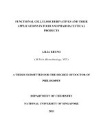
Figure: 1.1 Graphene being the basic building block of all graphitic materials namely
Fullerenes (C
60
), CNT and 3D graphite.
[5]
(Reproduced from ref.[5])
Graphene is described as a “wonderful material” since it possessed high values of
thermal conductivity (~5000Wm
-1
K
-1
),
[6,7]
Young’s modulus (~1100 GPa),
[6,8]
specific
surface area (theoretical value: 2630 m
2
g
-1
),
[6,9]
fracture strength (125 GPa),
[6,8]
high
chemical stability and high optical transmittance.
[6]
1.2. Chemically Converted Graphene (CCG)
To date, graphene has been produced by various techniques such as chemical vapor
deposition (CVD),
[12]
epitaxial growth
[11]
and micro-mechanical exfoliation
[2]
for device and
fundamental purposes.
[10]
Apart from these techniques, chemical exfoliation of graphite to