Characterization of interfacial mechanical properties using wedge indentation method 2
Bạn đang xem bản rút gọn của tài liệu. Xem và tải ngay bản đầy đủ của tài liệu tại đây (6.94 MB, 2 trang )
F
F
p
b
4
s
i
i
*
i
F
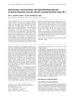
ig. 4.2: Cr
o
F
IB: (a) no
By
e
p
lane view
b
e easily id
e
4
.5b). In a
s
omewhat
h
i
ndentation
,
i
nterfacial
c
*
See Appe
n
i
mpression.
o
ss-section
a
interfacial
c
e
xamining
t
(Figs.4.4 a
n
e
ntified an
d
ddition, th
e
h
igher than
,
the pop-i
n
c
rack in th
n
dix A for t
h
a
l views of
c
rack; (b) -
t
he FIB cro
s
n
d 4.5) im
a
d
associate
d
e
initiatio
n
that for th
e
n
occu
r
s at
e FIB cro
s
h
e schemat
90° wedge
(d) interfa
c
s
s-sectiona
l
a
ges of the
d
to a centra
n
of interf
a
e
pop-in. F
o
2 mN on
t
s
s-sectional
ic diagram
indentatio
n
c
ial crack p
r
l
view
*
(Fi
g
wedge im
p
l crack alo
n
a
cial crack
o
r instance
,
t
he P-h cur
v
view (Fig
.
of FIB cutt
i
n
s on the M
r
opagation.
g
s.4.2 and 4
p
ressions, t
h
n
g the wed
g
is found
t
,
in the cas
e
v
e (Fig.4.1
(
.
4.2(a), cr
o
i
ng on wed
g
C
SQ/Si syst
e
[1]
.3) and the
h
e pop-in e
v
g
e tip (Figs.
4
t
o occur a
t
e
of the 90
(
a)) but th
e
o
ss-sectione
d
g
e indentat
i
C
hapter 4
67
em
using
FESEM
v
ent can
4
.4a and
t
a load
° wedge
e
re is no
d
at the
i
on
m
a
F
u
m
iddle of t
h
a
central cr
a
F
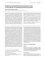
ig. 4.3: C
r
u
sing FIB:
(
h
e wedge i
m
a
ck at this l
o
r
oss-sectio
n
(
a) no inter
f
m
pressio
n
),
o
ad.
n
al views
o
f
acial crack
and the F
E
o
f 120° we
; (b) – (d) i
n
E
SEM plan
e
dge in
d
ent
a
n
terfacial c
r
e
view (Fig
a
tions on t
h
r
ack propa
g
C
.4.4(a)) sh
o
h
e MSQ/S
i
g
ation. [1]
C
hapter 4
68
o
ws only
i
system


![Báo cáo khoa học: Characterization of the bioactive conformation of the C-terminal tripeptide Gly-Leu-Met-NH2 of substance P using [3-prolinoleucine10]SP analogues pdf](https://media.store123doc.com/images/document/14/rc/ty/medium_tyq1394220086.jpg)