Development of a miniature low cost UAV helicopter autopilot platform and formation flight control of UAV teams 1
Bạn đang xem bản rút gọn của tài liệu. Xem và tải ngay bản đầy đủ của tài liệu tại đây (7.53 MB, 89 trang )
DEVELOPMENT OF A MINIATURE LOW-COST UAV
HELICOPTER AUTOPILOT PLATFORM AND
FORMATION FLIGHT CONTROL OF UAV TEAMS
YUN BEN
(B.Eng and M.Eng, Harbin Institute of Technology, China)
A THESIS SUBMITTED
FOR THE DEGREE OF DOCTOR OF PHILOSOPHY
DEPARTMENT OF ELECTRICAL & COMPUTER ENGINEERING
NATIONAL UNIVERSITY OF SINGAPORE
2010
Summary
Unmanned aerial vehicles (UAVs) have become a popular research topic worldwide recently.
Their important role and their great potential are being explored continuously. Among
various UAVs, small UAV helicopter has special attractiveness to the academic circle, due
to its small size, unique flight capacities, outstanding maneuverability, and low cost. Nowa-
days with the fast development in manufacturing skill and martial science, constructing a
small-scale UAV helicopter which is upgraded from advanced hobby-purpose helicopter be-
comes feasible and affordable. Its unlimited potential for various practical implementations
motivates our NUS UAV research team to carry out a comprehensive study and exploration.
One of our goals is to develop a miniature UAV helicopter platform and construct several
UAVs as test beds towards implementing multiple UAV team formation flight. With limited
research budget, low-cost miniature UAV helicopter was chosen as our research platform.
Developing an autonomous miniature UAV helicopter is a challenge for several reasons.
Firstly, helicopters are inherently unstable and capable of exhibiting high acceleration rates.
They are highly sensitive to control inputs and require high frequency feedback with mini-
mum delay for stability. Secondly, the dynamics of helicopters are unstable, multivariable,
highly coupled, which is thus hard for modeling. Thirdly, helicopters have limited on-board
power and payload capacity. Flight control systems must be compact, efficient, and light
weight for effective on-board integration. As the saying goes “the lower the price, the worse
quality of the goods”, smaller and lower cost sensors also mean lower performance, which
makes the things even harder. Finally, helicopters are extremely dangerous.
Our research on miniature UAV helicopters started from the year 2003. The overall
design and control procedure for the miniature UAV is similar as the small-scale UAV
helicopters, which includes: (1) hardware construction, (2) software system development,
(3) dynamic modeling, and (4) control law design and implementation. Besides these, with
a low-cost micro-size Inertial Measurement Unit (IMU) and a miniature UAV helicopter, we
need thoroughly calibrate sensors, optimize our Global Position System (GPS) information
and also self-develop attitude determination algorithm. In spite of the difficulties, one of
the advantages of choosing a miniature UAV helicopter as the platform lies in that the
experiment with a miniature helicopter is simple: it is easy to find a small area for testing
i
Summary ii
and thus can greatly reduce our previous research time. This is the reason why we are able
to extend our research in the formation flight.
The fundamental requirement for carrying our UAV research is having reliable miniature
UAV helicopters in hand. In the first year, we have constructed and tested the miniature
UAV helicopter. One compact with special design , for constructing a miniature UAV heli-
copter platform with minimum payload and lowest cost has been summarized and proposed.
After the autopilot system hardware was integrated, software was developed to ensure all of
the hardware components work properly. Several software necessaries such as sensor data
collection and filtering, control signal collection, and data storage were implemented on it.
Since a dynamic model is needed before designing the controller, based on the classic mod-
eling method, we first developed a linear multi-input multi-output (MIMO) model through
time-domain and frequency-domain system identification. To avoid flight crash due to tem-
porary GPS signal block or failure, a special robust cascaded modeling and control method
was proposed. The autopilot system performs very well in hovering and low speed flying in
real flight experiment.
With the reliable UAV helicopter platform at hand, we then further extended our re-
search in the formation flight field. We present a full scheme for the formation flight of
multiple UAV helicopters. Moreover, we adopt the leader-follower pattern to maintain a
fixed geometrical formation while navigating the UAVs following certain trajectories. More
specifically, the leader is commanded to fly on some predefined trajectories, and each fol-
lower is controlled to maintain its position in formation using the measurement of its inertial
position and the information of the leader’s position and velocity, obtained through a wire-
less Compact Flash (CF) card. More specifications are made for multiple UAV formation
flight. In order to avoid possible collisions of UAV helicopters in the actual formation flight
test, a collision avoidance scheme based on some predefined alert zones and protected zones
is employed. Simulations and real flight experimental results have verified that our design
is effective.
To conclude this work, we summarize the research achievements and contribution, then
provide the meaningful research directions for future.
Acknowledgements
“The important thing in life is to have a great aim, and the determination to attain it”.
Johan Wolfgang von Goethe, (German Poet and dramatist).
It is beyond doubt that the work in this thesis can not be completed without the support,
advice, and encouragement of others, teachers, colleagues, friends, and family members. In
this acknowledgement, I wish to formally acknowledge their support and pay special thanks
to the role they have played during the course of this project.
First and foremost, I would like to gratefully and sincerely thank Prof. Ben M. Chen for
his guidance, understanding, and patience in all aspects of this research during my studies
at National University of Singapore.
I also owe a debt of gratitude to Dr. Kai-Yew Lum and Prof. T. H. Lee for their assis-
tance and counsel, and for the generous time and invaluable insights that they shared with
me in reviewing my work, as well as for having served as my academic advisor throughout
this endeavor.
The members of the UAV group have contributed immensely to my personal and pro-
fessional time at NUS. The group has been a source of friendships as well as good advice
and collaboration. I have had the pleasure to work with all of them. Special thanks to Mr.
Alvin Cai, who has explored the avionics in his final year project and Dr. Guowei Cai who
has explored the MIMO system modeling. I am especially grateful for them: Dr. Kemao
Peng, Dr. Miaobo Dong, Mr. Feng Lin and Mr. Xiangxu Dong.
To my family, for their reassuring confidence in the inevitable conclusion of this work,
in particular I would like to thank my mother for her unwavering faith in me, my father
who I deeply admire, and my brothers for their strong support, of which I’m truly grateful.
Finally I would like to thank the two most important people in my life, my wife and
daughter. You mean more to me than life itself. Thank you for your love, support, encour-
agement, and most importantly, laughter. Thank you.
iii
Contents
Summary i
Acknowledgements iii
Contents iv
List of Figures viii
List of Tables xi
Nomenclature xii
1 Introduction 1
1.1 General Overview . . . . . . . . . . . . . . . . . . . . . . . . . . . . . . . . . . 1
1.2 Project Background . . . . . . . . . . . . . . . . . . . . . . . . . . . . . . . . 3
1.3 Technical Background . . . . . . . . . . . . . . . . . . . . . . . . . . . . . . . 5
1.3.1 Coordinate Frames Definition . . . . . . . . . . . . . . . . . . . . . . . 6
1.3.2 Attitude Definition . . . . . . . . . . . . . . . . . . . . . . . . . . . . . 8
1.3.3 Actuator Definitions . . . . . . . . . . . . . . . . . . . . . . . . . . . . 9
1.4 Goals and Objectives . . . . . . . . . . . . . . . . . . . . . . . . . . . . . . . . 10
1.5 Outline of this Thesis . . . . . . . . . . . . . . . . . . . . . . . . . . . . . . . 11
iv
CONTENTS v
2 Systematic Construction of a Miniature UAV Platform 13
2.1 The UAV System Hardware . . . . . . . . . . . . . . . . . . . . . . . . . . . . 14
2.1.1 Bare Helicopter: TREX 450 . . . . . . . . . . . . . . . . . . . . . . . . 14
2.1.2 Avionic System . . . . . . . . . . . . . . . . . . . . . . . . . . . . . . . 16
2.1.3 Servo Control Module . . . . . . . . . . . . . . . . . . . . . . . . . . . 23
2.1.4 Other Issues Related to the UAV Design . . . . . . . . . . . . . . . . . 28
2.2 Software Development . . . . . . . . . . . . . . . . . . . . . . . . . . . . . . . 29
2.2.1 Onboard Software . . . . . . . . . . . . . . . . . . . . . . . . . . . . . 30
2.2.2 The Ground Station: a Monitoring Program . . . . . . . . . . . . . . 33
2.3 Ground and Flight Test Evaluation . . . . . . . . . . . . . . . . . . . . . . . . 35
2.3.1 EMI Test . . . . . . . . . . . . . . . . . . . . . . . . . . . . . . . . . . 35
2.3.2 Vibration Test . . . . . . . . . . . . . . . . . . . . . . . . . . . . . . . 35
2.3.3 Manual Flight Test . . . . . . . . . . . . . . . . . . . . . . . . . . . . . 36
2.4 conclusion . . . . . . . . . . . . . . . . . . . . . . . . . . . . . . . . . . . . . . 40
3 Robust GPS Enhancement and Attitude Determination 41
3.1 Sensors Calibration . . . . . . . . . . . . . . . . . . . . . . . . . . . . . . . . . 42
3.1.1 Magnetometer Hard and Soft Iron Calibration . . . . . . . . . . . . . 43
3.2 Typical Filtering Algorithms . . . . . . . . . . . . . . . . . . . . . . . . . . . 45
3.2.1 Complimentary Filtering Algorithm . . . . . . . . . . . . . . . . . . . 45
3.2.2 Kalman Filtering Algorithm . . . . . . . . . . . . . . . . . . . . . . . . 48
3.2.3 Extended Kalman filtering Algorithm . . . . . . . . . . . . . . . . . . 50
3.2.4 Discrete-time H
∞
Filtering . . . . . . . . . . . . . . . . . . . . . . . . 52
3.2.5 Comparison of the Filtering Algorithms . . . . . . . . . . . . . . . . . 54
3.3 Atttitude Determination . . . . . . . . . . . . . . . . . . . . . . . . . . . . . . 54
3.3.1 Determination of Aircraft Attitude . . . . . . . . . . . . . . . . . . . . 55
3.3.2 H
∞
Filtering for Euler-angles Determination . . . . . . . . . . . . . . 58
3.3.3 Experimental Results . . . . . . . . . . . . . . . . . . . . . . . . . . . 62
3.4 GPS Signal Enhancement . . . . . . . . . . . . . . . . . . . . . . . . . . . . . 64
3.4.1 Position Signals . . . . . . . . . . . . . . . . . . . . . . . . . . . . . . . 65
3.4.2 H
∞
Filtering for GPS Position Signal Enhancement . . . . . . . . . . 69
3.4.3 Position Determination Experimental Results . . . . . . . . . . . . . . 69
3.5 Conclusion . . . . . . . . . . . . . . . . . . . . . . . . . . . . . . . . . . . . . 72
CONTENTS vi
4 Dynamic Modeling and Control of the Miniature UAV Helicopter 73
4.1 Data Collection and Preprocessing . . . . . . . . . . . . . . . . . . . . . . . . 74
4.1.1 Select the Input Signals . . . . . . . . . . . . . . . . . . . . . . . . . . 74
4.1.2 Collect Flight Test Data . . . . . . . . . . . . . . . . . . . . . . . . . . 76
4.1.3 Preprocessing of the Raw Dataset . . . . . . . . . . . . . . . . . . . . 80
4.2 Helicopter Aerodynamics Model Structure . . . . . . . . . . . . . . . . . . . . 81
4.2.1 6 Degree of Freedom (DOF) Rigid-body Dynamics . . . . . . . . . . . 82
4.2.2 Coupled Rotor Flapping Dynamics . . . . . . . . . . . . . . . . . . . . 82
4.2.3 Yaw Rate Gyro Dynamics . . . . . . . . . . . . . . . . . . . . . . . . . 83
4.3 MIMO Modeling and Control Method . . . . . . . . . . . . . . . . . . . . . . 84
4.3.1 Modeling of BabyLion UAV Helicopter . . . . . . . . . . . . . . . . . . 84
4.3.2 Control Law Design for BabyLion UAV Helicopter . . . . . . . . . . . 91
4.4 Cascaded Modeling and Control Method . . . . . . . . . . . . . . . . . . . . 94
4.4.1 Cascaded Modeling . . . . . . . . . . . . . . . . . . . . . . . . . . . . . 95
4.4.2 Control Law Design for BabyLion UAV Helicopter . . . . . . . . . . . 101
4.5 Simulation and Implementation Results . . . . . . . . . . . . . . . . . . . . . 104
4.5.1 MIMO Control Method . . . . . . . . . . . . . . . . . . . . . . . . . . 104
4.5.2 Cascaded Control Implementation Results . . . . . . . . . . . . . . . . 107
4.5.3 Comparison of the Two Control Methods . . . . . . . . . . . . . . . . 113
4.6 Conclusion . . . . . . . . . . . . . . . . . . . . . . . . . . . . . . . . . . . . . 118
5 Formation Control Modeling, Control Law Design and Implementation 120
5.1 Model of a Leader-Follower Formation Flight . . . . . . . . . . . . . . . . . . 121
5.2 Control of Formation Flight . . . . . . . . . . . . . . . . . . . . . . . . . . . . 126
5.2.1 Dynamic Inversion Control Law for Outer-loop Control of the Follower
UAV . . . . . . . . . . . . . . . . . . . . . . . . . . . . . . . . . . . . . 127
5.2.2 Leader-Follower Formation Flight Input Constraint . . . . . . . . . . . 128
5.2.3 Multiple UAV Formation Flight . . . . . . . . . . . . . . . . . . . . . . 129
5.3 Collision Avoidance . . . . . . . . . . . . . . . . . . . . . . . . . . . . . . . . 135
5.3.1 Collision Avoidance for Two UAV Case . . . . . . . . . . . . . . . . . 136
5.3.2 Multiple UAV Group Collision Avoidance . . . . . . . . . . . . . . . . 142
5.3.3 Obstacle Avoidance . . . . . . . . . . . . . . . . . . . . . . . . . . . . 142
5.4 Formation Flight Test Result . . . . . . . . . . . . . . . . . . . . . . . . . . . 145
5.4.1 Formation Flight Experiment Setup . . . . . . . . . . . . . . . . . . . 146
5.4.2 Test Result . . . . . . . . . . . . . . . . . . . . . . . . . . . . . . . . . 148
5.5 conclusion . . . . . . . . . . . . . . . . . . . . . . . . . . . . . . . . . . . . . . 151
CONTENTS vii
6 Conclusions 153
6.1 Contributions . . . . . . . . . . . . . . . . . . . . . . . . . . . . . . . . . . . 154
6.2 Future Work . . . . . . . . . . . . . . . . . . . . . . . . . . . . . . . . . . . . 155
A Publication/Submitted Paper List 158
List of Figures
1.1 The UAV helicopter, BabyLion. . . . . . . . . . . . . . . . . . . . . . . . . . . 4
1.2 UAV helicopter family in NUS. . . . . . . . . . . . . . . . . . . . . . . . . . . 4
1.3 Reference frames. . . . . . . . . . . . . . . . . . . . . . . . . . . . . . . . . . . 7
1.4 The formation frame. . . . . . . . . . . . . . . . . . . . . . . . . . . . . . . . . 8
1.5 Definition of normal Euler angles. . . . . . . . . . . . . . . . . . . . . . . . . . 9
2.1 Basic helicopter - TREX 450 . . . . . . . . . . . . . . . . . . . . . . . . . . . 15
2.2 The avionics system. . . . . . . . . . . . . . . . . . . . . . . . . . . . . . . . . 16
2.3 Functional system architecture [31]. . . . . . . . . . . . . . . . . . . . . . . . . 17
2.4 MNAV100CA. . . . . . . . . . . . . . . . . . . . . . . . . . . . . . . . . . . . . 19
2.5 Stargate development platform (processor board and daughter card). . . . . . 20
2.6 AmbiCom wireless 802.11 card. . . . . . . . . . . . . . . . . . . . . . . . . . . 22
2.7 Auto mode switch on RC transmitter. . . . . . . . . . . . . . . . . . . . . . . 25
2.8 PPM signal and its decoded output. . . . . . . . . . . . . . . . . . . . . . . . 25
2.9 MNAV mode switching function. . . . . . . . . . . . . . . . . . . . . . . . . . 26
2.10 A typical receiver circuit diagram with PPM decoding. . . . . . . . . . . . . . 26
2.11 A typical receiver print circuit board (PCB) with PPM decoding. . . . . . . . 27
2.12 UAV avionics. . . . . . . . . . . . . . . . . . . . . . . . . . . . . . . . . . . . . 29
2.13 Soft model architecture [31]. . . . . . . . . . . . . . . . . . . . . . . . . . . . . 31
2.14 Scheduling time line. . . . . . . . . . . . . . . . . . . . . . . . . . . . . . . . . 32
2.15 Ground station GUI with NUS campus map. . . . . . . . . . . . . . . . . . . 34
2.16 UAV in flight. . . . . . . . . . . . . . . . . . . . . . . . . . . . . . . . . . . . . 34
2.17 Manual hovering flight test. . . . . . . . . . . . . . . . . . . . . . . . . . . . . 40
3.1 Calibration example: accelerometer offset, scale factor compensation. . . . . . 42
viii
LIST OF FIGURES ix
3.2 Effects of soft/ hard-iron distortions. . . . . . . . . . . . . . . . . . . . . . . . 44
3.3 Magnetic calibration readings. . . . . . . . . . . . . . . . . . . . . . . . . . . . 44
3.4 Rate gyro performance. Solid: the true attitud; Dash: integrated output of
the rate gyro. . . . . . . . . . . . . . . . . . . . . . . . . . . . . . . . . . . . . 46
3.5 Accelerometer performance. solid: the true attitude; Dash: the accelerometer
estimation. . . . . . . . . . . . . . . . . . . . . . . . . . . . . . . . . . . . . . 46
3.6 Attitude angle estimation using accelerometer. . . . . . . . . . . . . . . . . . 47
3.7 Comparison of Euler angles estimated by H
∞
filter (solid line) and those
estimated by NAV420 (dashed line). . . . . . . . . . . . . . . . . . . . . . . . 63
3.8 The measured body-frame y-axis position and velocity during a hovering flight
from GPS. . . . . . . . . . . . . . . . . . . . . . . . . . . . . . . . . . . . . . . 66
3.9 The position integrated by velocity (bold line) and that measured by GPS
receiver (thin line). . . . . . . . . . . . . . . . . . . . . . . . . . . . . . . . . . 67
3.10 Comparison of the x-y position estimated by H
∞
filter (bold line) and that
measured by NAV100CA (thin line). . . . . . . . . . . . . . . . . . . . . . . . 70
3.11 Comparison of the position estimated by H
∞
filter (solid line) and that mea-
sured by NAV100CA (dashed line). . . . . . . . . . . . . . . . . . . . . . . . . 71
4.1 Typical frequency sweep input signal. . . . . . . . . . . . . . . . . . . . . . . 76
4.2 Typical doublet input signal. . . . . . . . . . . . . . . . . . . . . . . . . . . . 77
4.3 Input signals in the yaw channel perturbation experiment. . . . . . . . . . . . 78
4.4 Position outputs in the yaw channel perturbation experiment. . . . . . . . . . 78
4.5 Velocity outputs in the yaw channel perturbation experiment. . . . . . . . . . 79
4.6 Angular rates in the yaw channel perturbation experiment. . . . . . . . . . . 79
4.7 Euler angles in the yaw channel perturbation experiment. . . . . . . . . . . . 80
4.8 An illustration for tip-path-plane. . . . . . . . . . . . . . . . . . . . . . . . . . 83
4.9 Verification of the identified model. . . . . . . . . . . . . . . . . . . . . . . . . 90
4.10 General flight control scheme for UAVs. . . . . . . . . . . . . . . . . . . . . . 91
4.11 General flight control scheme for UAVs. . . . . . . . . . . . . . . . . . . . . . 98
4.12 Verification of the identified model. . . . . . . . . . . . . . . . . . . . . . . . . 100
4.13 Outputs of hovering flight simulation. . . . . . . . . . . . . . . . . . . . . . . 105
4.14 Control inputs of hovering flight simulation. . . . . . . . . . . . . . . . . . . . 106
4.15 Outputs of automatic hovering flight test. . . . . . . . . . . . . . . . . . . . . 106
4.16 Control inputs of automatic hovering flight. . . . . . . . . . . . . . . . . . . . 107
LIST OF FIGURES x
4.17 Automatic hovering flight test with cascaded control. . . . . . . . . . . . . . . 112
4.18 UAV in flight . . . . . . . . . . . . . . . . . . . . . . . . . . . . . . . . . . . . 113
4.19 Automatic circle path tracking flight test. . . . . . . . . . . . . . . . . . . . . 117
5.1 TREX450-XL Babylion formation fleet . . . . . . . . . . . . . . . . . . . . . . 121
5.2 Leader-follower UAV formation geometry. . . . . . . . . . . . . . . . . . . . . 122
5.3 The controller structure for the follower UAV. . . . . . . . . . . . . . . . . . . 128
5.4 The lateral flight limitation of UAV. . . . . . . . . . . . . . . . . . . . . . . . 129
5.5 Horizontal level plane formation geometry for 3 UAVs. . . . . . . . . . . . . . 130
5.6 Multiple UAV group communication, global/local information is distributed
by leader UAV. . . . . . . . . . . . . . . . . . . . . . . . . . . . . . . . . . . . 134
5.7 Formation basic shape: line . . . . . . . . . . . . . . . . . . . . . . . . . . . . 135
5.8 Formation transformation. . . . . . . . . . . . . . . . . . . . . . . . . . . . . . 135
5.9 Multiple UAV group maneuvers of formation, rejoin, reconfiguration, splitting
and deformation. . . . . . . . . . . . . . . . . . . . . . . . . . . . . . . . . . . 136
5.10 Alert zone and protected zone surrounding a UAV. . . . . . . . . . . . . . . . 137
5.11 The relative configuration in horizontal view, showing the protected zone and
alert zone. . . . . . . . . . . . . . . . . . . . . . . . . . . . . . . . . . . . . . . 138
5.12 Multiple UAV group with an intruder. . . . . . . . . . . . . . . . . . . . . . . 142
5.13 UAV and an obstacle. . . . . . . . . . . . . . . . . . . . . . . . . . . . . . . . 143
5.14 UAV avoids an obstacle. . . . . . . . . . . . . . . . . . . . . . . . . . . . . . . 145
5.15 UAV group avoids obstacles. . . . . . . . . . . . . . . . . . . . . . . . . . . . . 146
5.16 Design overview of data flow among helicopters in a “leader-chaser” flight
experiment . . . . . . . . . . . . . . . . . . . . . . . . . . . . . . . . . . . . . 148
5.17 UAVs in formation flight, (Screen capture from ground video camera) . . . . 149
5.18 Flight result, (a) Horizontal plane. Red – virtual leader’s trajectory; Blue –
follower trajectory; Cyan – follower reference. . . . . . . . . . . . . . . . . . . 150
5.19 Flight result, (b) Longitude and Latitude. Dashed line – follower trajectory;
Solid line – follower reference. . . . . . . . . . . . . . . . . . . . . . . . . . . . 150
5.20 XY plot of flight data for leader-follower formation flight. . . . . . . . . . . . 151
5.21 Tracking separation between the leader and follower UAVs . . . . . . . . . . . 152
List of Tables
2.1 Specifications of TREX 450 helicopter compared with Raptor 90 helicopter . 15
2.2 Specifications of MNAV100CA compared with NAV420CA . . . . . . . . . . . 18
2.3 Specifications of wireless card: data rate and range . . . . . . . . . . . . . . 22
2.4 Power utilisation . . . . . . . . . . . . . . . . . . . . . . . . . . . . . . . . . . 23
4.1 Trim values for the tested flight conditions . . . . . . . . . . . . . . . . . . . . 81
4.2 State and input variables with the physical meanings . . . . . . . . . . . . . . 87
4.3 Estimated parameters through system identification, MIMO modeling method. 88
4.4 Estimated parameters through first principle modeling approach . . . . . . . 89
4.5 Estimated parameters through system identification, cascaded modeling method. 99
xi
Nomenclature
Latin variables
A State matrix in linearized model structure
B Input matrix in linearized model structure
B
body→L
The transformation matrix from the UAVs body frame to the leaders wind frame.
B
L→body
The transformation matrix from the leaders wind frame to the UAVs body frame.
B
b2n
Velocity transformation matrix from body frame to NED frame
B
n2b
Velocity transformation matrix from NED frame to body frame
B
W L
Velocity transformation matrix from follower’s body frame to leader’s body frame
b
x
bias in the GPS velocity information
C Output matrix in linearized model structure
f Forward error in the formation frame
f
c
Forward clearance in the formation frame
g The acceleration of gravity
h Heave error in the formation frame
h
c
Heave clearance in the formation frame
I Moment of inertia matrix
I
xx
Rolling moment of inertia
I
yy
Pitching moment of inertia
I
zz
Yawing moment of inertia
i
s
Main shaft tilting angle
K
I
Integral gains of the embedded controller
K
P
Proportional gains of the embedded controller
K
a
Proportional gain of amplifier circuit
K
col
Proportional gain of the main blade’s collective pitch change to collective pitch servo input
K
sb
Contribution from stabilzer bar flapping to main blade’s cyclic pitch
K
ped
Proportional gain of the tail blade’s collective pitch change to tail rotor servo deflection
l Lateral error in the formation frame
l
c
Lateral clearance in the formation frame
M
b
Moment vector
M
bx
Body frame rolling moment component
xii
Nomenclature xiii
M
by
Body frame pitching moment component
M
bz
Body frame yawing moment component
M
hf
Pitching moment generated by horizontal fin
M
mr
Pitching moment generated by main rotor
M
u
Pitching speed moment derivative
M
v
Pitching speed moment derivative
m Mass of helicopter
m
x
magnetometer output in x-axis
m
y
magnetometer output in y-axis
m
z
magnetometer output in z-axis
O
e
The origin point of NED frame
O
ABC
The origin point of body frame
O
f
The origin point of formation axis frame
P
b
Position vector in body frame
P
n
Position vector in NED frame
p
xb
Body frame x-axis position
p
xn
NED frame x-axis position
p
yb
Body frame y-axis position
p
yn
NED frame y-axis position
p
zb
Body frame z-axis position
p
zn
NED frame z-axis position
p
∗
x
The true position with reference to GPS position.
p Body frame rolling angular velocity
q Body frame pitching angular velocity
R Main blade radius
r Body frame yawing angular velocity
r
sb
Stabilizer bar inner radius
T Main rotor thrust force
u Body frame x-axis velocity
u
a
Body frame x-axis velocity relative to the airmass
u
n
NED frame x-axis velocity
u
wind
Body frame x-axis wind velocity
V
a
Velocity vector relative to the airmass
V
b
Velocity vector in body frame
V
n
Velocity vector in NED frame
V
trim
Trimmed flight speed in steady state
V
wind
Velocity vector of wind
v Body frame y-axis velocity
v
a
Body frame y-axis velocity relative to the airmass
v
n
NED frame y-axis velocity
Nomenclature xiv
v
wind
Body frame y-axis wind velocity
w Body frame z-axis velocity
w
a
Body frame z-axis velocity relative to the airmass
w
n
NED frame z-axis velocity
w
wind
Body frame z-axis wind velocity
X
a
Body frame x-axis rotor spring derivative
X
ABC
Body frame x-axis spring derivative
X
e
NED frame x-axis rotor spring derivative
X
f
formation frame x-axis spring derivative
X
N ED
NED frame x-axis spring derivative
X
sf
magnetometer soft calibration x-axis ratio
X
of f
magnetometer soft calibration x-axis bias
X
u
Body frame x-axis speed derivative
Y
ABC
Body frame y-axis spring derivative
Y
b
Body frame y-axis rotor spring derivative
Y
e
Body frame y-axis rotor spring derivative
Y
f
formation frame y-axis spring derivative
Y
N ED
NED frame y-axis spring derivative
Y
sf
magnetometer soft calibration y-axis ratio
Y
of f
magnetometer soft calibration y-axis bias
Y
v
Body frame y-axis speed derivative
Y
tr
Tail rotor thrust force
y Output vector in linearized model structure
Z
ABC
Body frame z-axis spring derivative
Z
col
Heave direction control derivative
Z
e
NED frame z-axis spring derivative
Z
f
formation frame z-axis spring derivative
Z
N ED
NED frame z-axis spring derivative
Z
w
Body frame z-axis speed derivative
Greek variables
φ Rolling angle in NED frame
θ Pitching angle in NED frame
θ
col
Collective pitch angle of main blade
θ
ped
Collective pitch angle of tail blade
ψ Yawing angle in NED frame
γ
sb
Stabilizer bar rotor time constant
τ Main rotor time constant
Ω Main rotor rotating speed governed by engine governor
Ω
b
Angular velocity vector in body frame
Nomenclature xv
Ω
n
Angular velocity vector in NED frame
δ
lat
Aileron servo input
δ
lon
Elevator servo input
δ
col
Collective pitch servo input
δ
ped
Rudder servo input
¯
δ
ped
Tail rotor servo (rudder servo) deflection
µ Advance ratio
Abbreviations
AGC Automatic Gain Control
AHRS Attitude and Heading Reference Systems
CG Center of Gravity
CIFER Comprehensive Identification from FrEquency Responses software package
CF Compact Flash
CPU Central Processing Unit
CZT Chirp z-transform
DC Direct Current
DI Dynamic Inversion
DOF Degree-of-freedom
EKF Extended Kalman Filter
EMI Electromagnetic Interference
GUI Graphical User Interface
GPS Global Positioning System
IDENT Time-domain Identification Toolkit Integrated in MATLAB
IF Intermediate-Frequency
IMU Inertial Measurement Unit
INS Inertial navigation system
I/O Input Output
JTAG Joint Test Action Group
LQG Linear Quadratic Gaussian
LQR Linear Quadratic Regulator
Li-Po Lithium-Polymer
MAVs Miniature Aerial Vehicle
MEMS Micro-Electro-Mechanical System
MIMO Multi-Input Multi-Output
NED North-East-Down
NUS National University of Singapore
PCB Printed Circuit Board
PCMCIA Personal Computer Memory Card International Association
PID Proportional-Integral-Derivative
Nomenclature xvi
POSIX Portable Operating System Interface for UNIX
PPM Pulse-position Modulation
RC Radio-Controlled
RF Radio Frequency
RPM Rotations Per Minute
RPV Remotely Piloted Vehicle
RR Round-Robin
RTOS Real-time Operating System
SISO Single-Input Single-Output
TCP Transmission Control Protocol
TPP Tip-Path-Plane
UAV Unmanned Aerial Vehicle
UDP User Datagram Protocol
USB Universal Serial Bus
2D Two-Dimensional
Chapter 1
Introduction
1.1 General Overview
Unmanned aerial vehicles, or commonly known as UAVs, are autonomous flying vehicles
equipped with sensing devices and possibly weapons. The UAVs have many potential mili-
tary and civil applications. They can avoid the human risk inherent to human-piloted aerial
vehicles, particularly in missions in hostile environments, for example, reconnaissance over
hostile territories, or attacking battle damage of enemy targets (see [18]). After World War
II, some countries began to develop their UAVs for military purposes. With the rapid devel-
opment of high technology nowadays, UAVs have become very feasible lately due to recent
advances in sensor technologies, data processing hardware, and propulsion systems. In the
last two decades, UAVs have attracted a significant interest. More and more effort has been
put into this area.
Today there is a wide range of UAVs including rotor helicopters and fix-wing aircrafts
used all over the world which are designed for different levels of performance depending
on their applications. UAVs range in size from the man-portable (mini- and micro-UAVs),
which are powered by electricity and usually weigh less than 2 kg, small-scale UAV which are
powered by oil or gasoline and typically weighs 10-50 kg, to full-size aircraft (large size UAV).
Among various UAVs, the large UAVs are used mostly for military purposes. In contrast, the
1
CHAPTER 1. 2
smaller, tactical UAVs are being developed to support tactical units to perform very short
range “over the hill” and “around the corner” reconnaissance, and assist in protection. While
each mission requires a different profile and capabilities, the man portable Miniature Aerial
Vehicles (MAVs) are designed to provide reasonably good performance at an affordable price.
Miniature UAV helicopter also has special attractiveness to the academic circle because of
their smaller size, expendable lower cost, outstanding maneuverability, ease of uses, and
wide range of capabilities.
The smaller size UAV helicopters are commonly upgraded from radio-controlled hobby
helicopters by assembling an avionic system. They are one of the best platforms applied
as typical plants for academic research as they can be docilely manipulated in a manual
mode and can also be easily switched to an automatic mode. Many research groups have
constructed their own small scale UAV helicopters for their research purposes (see [27]).
Success has been achieved in many research areas such as modeling and identification (see
[43]), control techniques implementation (see [33]), aerial image processing (see [52], [42]),
to name a few. However, due to the highly dynamic behavior of helicopter, limited payload
capability and lack of highly accurate sensors, miniature UAVs are still rare.
Designing a miniature UAV helicopter is a challenging job, there are many aspects that
need to be thoroughly considered with the special constraints, such as:
1. hardware components selection which is limited by the budget and also the payload
capability;
2. modeling and control of a nonlinear Multiple input Multiple Output(MIMO) heli-
copter system which is the core issues of the research purpose;
3. software design which is usually programmed in an embedded system to collect
sensor data, send sensor information to the ground station, calculate command signal, and
issue the command to the actuators. The ground station receives remote data from the on-
board system for monitoring purposes. Other software capability includes sensor information
processing such as sensor filtering and optimization.
CHAPTER 1. 3
While a single autonomous UAV can be very useful in performing various tasks, multiple
UAVs operating as a team to accomplish a given task cooperatively may offer even greater
advantages in certain applications, such as in target search and detection in a large area of
coverage. With a mini-UAV platform being built, it is natural for us to expand our research
domain to the formation flight of multiple UAVs, as formation flight is one of the interesting
topics of further research in the UAV field [29].
In the next sections of this chapter, a general project background on the work completed
by our NUS UAV-research team in the last five years will be addressed in Section 1.2.
In Section 1.3, a brief technical background of the designing a UAV helicopter will be
introduced. The objective and goal of the project is presented in Section 1.4 and an outline
of the remaining chapters will also be listed in Section 1.5.
1.2 Project Background
The research on small-scale UAV helicopters in National University of Singapore (NUS) has
started from year 2004. During the last five years, our NUS UAV research team has success-
fully constructed multiple small-scale UAV helicopters, developed efficient UAV software
systems, identified the high-fidelity linear and nonlinear dynamic models, and implemented
linear and nonlinear control laws to realize fully autonomous flight [10].
Since 2004, we have first developed a small-scale UAV helicopter, called HeLion, which
is upgraded from fuel-powered Raptor 90 helicopter (with 1.4 m rotor span), by equipping
with custom designed onboard computer system [10] with a comprehensive onboard and
ground station software system [22]. The bare helicopter weighs 4.85 kg and approximately
13 kg when mounted with the avionics system. An accurate aerodynamics model has been
derived for flight control law design and high performance automatic flight has been realized.
The same avionics system is also successfully applied for a relative bigger size UAV, called
Henglion, which is upgraded from a Copterworks helicopter with the weight of 20kg. Mean-
while, based on these achievements, we extended our research interest to develop mini-size
CHAPTER 1. 4
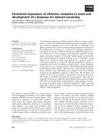
Figure 1.1: The UAV helicopter, BabyLion.
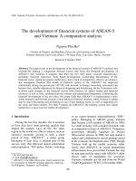
Figure 1.2: UAV helicopter family in NUS.
UAV based on smaller helicopters. An ultra low cost mini hobby RC helicopter, named
TREX 450 with 0.7 m rotor span, 700g weight is chosen for this purpose. Following the pre-
vious version of UAVs, we named this mini UAV as “Babylion”, which is shown in Fig. 1.1.
The collection of the UAVs developed by our NUS UAV group is shown in Fig. 1.2.
The major difference of BabyLion to Helion is that the size is scaled down by a math-
CHAPTER 1. 5
ematical scale in both weight and cost. Because of the smaller scale, the helicopter is now
battery-powered and very much lighter. The full flight time of BabyLion is about 8 minutes.
In the point of view of practical implementation, mini UAV helicopter has some unique ad-
vantages compared with the larger counterparts, including: 1) more agility; 2) portable by
one person, much easier and faster to assemble and move; 3) less noise; 4) lower cost (about
1/10 of the cost of the larger size UAV); 5) less dangerous during flight, and 6) more suitable
for forest, urban searching, and indoor flight. Besides this, BabyLion may also be an ideal
test bed for further research and technologies like vision based control and formation flying
or even swarming.
However due to its smaller size, extremely strict payload, and more sensitive aerody-
namics, constructing a mini UAV helicopter is much more difficult and challenging. The
disadvantages includes: 1) rapid dynamics with helicopter, which makes it hard for model-
ing; 2) low-cost small-size sensors with poorer performance; 3) actuator with relative lower
resolution; 4) working close to the GPS noise level such as the velocity is around: 0.5m/s
while the GPS velocity resolution is only 0.1-0.3 m/s, and position error is around 1.5 m,
while the GPS resolution is about 3 m. As such, most of research groups are still keen
on the Raptor 90 size (with 1.6 m rotor span, 5kg payload) or larger scale UAV helicopter
platforms.
Fortunately during the construction of HeLion UAV helicopter we have obtained a lot
of experience, which enables us to conquer various problems and successfully build up a
miniature UAV helicopter platform. The detailed hardware integration, sensor optimization
and control design theory will be discussed in Chapter 2 to 4.
1.3 Technical Background
In this section, we introduce some technical background, including cordinate frames, attitude
definition and actuator definition.
CHAPTER 1. 6
1.3.1 Coordinate Frames Definition
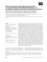
Three axis systems are utilized in both the modeling and the control of the control system.
These are the Earth axis system, the helicopter body axis systems and the formation axis
system.
Earth axis system (North East Down (NED) frame)
1. The Earth is assumed to be flat.
2. An arbitrary point on the Earths surface is defined as the origin (O
e
).
3. A right handed orthogonal system of axes (O
e
, X
e
, Y
e
, Z
e
) is defined at the origin.
Where X
e
points due North, Y
e
due East and Z
e
vertically down.
The NED frame is shown in Fig. 1.3
Aircraft body axis systems
Each aircraft has its own right handed orthogonal axis system (O
ABC
, X
ABC
, Y
ABC
,
Z
ABC
) mapped onto it.
1. The origin (O
ABC
) is located at the center of gravity of the aircraft and is constrained
to move with it.
2. X
ABC
is defined to point out through the aircrafts nose.
3. Y
ABC
out through the right hand wing.
4. Z
ABC
out through the bottom of the aircraft.
The axis system is constrained to move with the aircraft as it rolled, pitched, and yawed.
The body frame is also shown in Fig. 1.3
Formation axis system
The right handed orthogonal formation axis system (O
f
, X
f
, Y
f
, Z
f
) is used to specify
the offset of the target formation point from the lead aircraft.
1. The axis systems origin (O
f
) is located with the origin of the lead aircraft‘s body
axis system.
CHAPTER 1. 7
Figure 1.3: Reference frames.
CHAPTER 1. 8
Figure 1.4: The formation frame.
2. X
f
is defined to be parallel to the Earth‘s surface and to point in the compass heading
direction of the lead aircraft.
3. Y
f
completes the right hand orthogonal set.
4. Z
f
is defined to point vertically down towards the Earth.
The X − Y plane of the formation axis system therefore always remains parallel to the
surface of the Earth, with the X
f
axis aligned to the compass heading of the lead helicopter.
This is important because if the formation axis system rolled and pitched with the lead
helicopter in the same way as the body axis system, in low level flight with a reasonably
spaced formation, the trail aircraft could be forced into the ground by the rolling or pitching
motion of the lead [39]. The Formation frame is shown in Fig. 1.4
1.3.2 Attitude Definition
A set of the so-called normal Euler angles are commonly used to describe the orientation
of an aircraft. There are three Euler angles, which include the heading or yaw angle (ψ),
pitch angle (θ), and roll angle (φ). These angles are referenced to the local horizontal plane