Studies of self assembled monolayers on highly oriented pyrolytic graphite using scanning tunneling microscopy and computational simulation 6
Bạn đang xem bản rút gọn của tài liệu. Xem và tải ngay bản đầy đủ của tài liệu tại đây (678.86 KB, 17 trang )
ADSORPTION-INDUCED CHIRAL SAMs
CHAPTER 6
SURFACE-ADSORPTION INDUCED CHIRAL SELF-ASSEMBLED
MONOLAYERS OF HEXAALKYL HEXAPHENYLBENZENE (HHB) ON
HIGHLY ORIENTED PYROLYTIC GRAPHITE (HOPG)
6.1 Motivation
Since the separation of the sodium ammonium salt of racemic tartaric acid in
enantiomorphous crystals by Pasteur 150 years ago [1], the concept of chirality has
become an important research subject in chemistry. Chiral structures can be formed
not only from pure chiral molecules but also by the asymmetric assembly of the
molecules. In the two-dimensional realm, potential applications such as
enatio-selective heterogeneous catalysts [2, 3], nanometer scale patterning,
development of molecular electronic devices, and chemical sensors have drawn much
interest in the study of chiral structures on surfaces [2-25]. Depositing chiral
molecules on the surface is a typical way of generating a chiral surface [3-5], such as
(R,R)-tartaric acid have been successfully used as surface modifiers in
enantioselective heterogeneous catalysis [3, 4]. At the supramolecular level, chiral
structures may be formed by asymmetric assembly. For example, racemic mixtures of
certain chiral molecules spontaneously separate on the surface to form chiral domains
[6-9]. Hydrogen bonded chains [4, 11] have been reported to show chiral structures on
the surface. Studies of surface-adsorption induced chirality revealed that the
interaction between the substrate and adsorbate plays a key role in inducing structural
92
ADSORPTION-INDUCED CHIRAL SAMs
changes and the symmetry breaking which results in chirality [9, 12, 17, 21-25].
The development of the scanning probe techniques especially scanning tunneling
microscopy (STM) and atomic force microscopy (AFM) made it possible to locally
probe monolayers at atomic resolution. Spontaneous breaking of chiral symmetry by
achiral molecules in a Langmuir-Blodgett (LB) film was determined by Viswanathan
et al. with AFM [9]. Separation of achiral molecules into lattices with chiral packing
[9] and separation of chiral phases of chiral organic molecules in LB films have been
observed by AFM [26]. Chiral liquid crystals have also been investigated with STM
and found to form domains that exhibit two-dimensional chirality [27].
Supramolecular clusters of 1-nitronaphthalene on gold have been observed to
aggregate in 2D domains that are mirror images of each other [28].
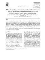
In this chapter we present an STM study at the liquid-solid interface of hexaalkyl
hexaphenylbenzenes (HHB) physisorbed onto a graphite surface.
Chemical Structure of HHB
This is an example of the formation of an asymmetric structure on the surface, which
involves the supramolecular assembly through van der Waals’ forces. The molecule
93
ADSORPTION-INDUCED CHIRAL SAMs
used in this experiment is hexaalkyl hexaphenylbenzene (HHB) - a precursor of the
polycyclic aromatic hydrocarbons (PAHs) with peripheral substituents. PAHs can
self-assemble into columnar mesophases [29] which are well suited materials for the
study of one-dimensional transport processes such as electrical conductivity [30] and
photoconductivity [31] along the columnar axis. Research toward electronics on the
scale of individual molecules can be performed by investigating highly ordered
monomolecular adsorbate layers of HHBs. Using the STM, single molecules in these
two-dimensional patterns can be visualized with submolecular resolution. At the same
time, information on their electronic properties can be obtained.
6.2 STM Results
6.2.1 STM Images of HHB
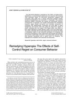
Fig 6.1 STM image of a monolayer of HHB on HOPG surfaces (100nm100nm, V
bias
=100mV,
I
set
=150pA)
94
ADSORPTION-INDUCED CHIRAL SAMs
Fig 6.1 displays the STM current image of a monolayer of HHB physisorbed at
the interface between organic solution and the basal plane of HOPG. It shows the
monolayer is right beside the step on the HOPG (bright part at the right-top corner).
The conductivity of the graphite is better than the organic monolayers therefore the
step becomes the brightest part in the STM current image. Each bright dot within the
SAMs corresponds to one physisorbed HHB molecule. The angle AOB=89±1,
which is almost a right angle. Section analysis of OA and OB (Fig 6.2) shows that the
neighbouring molecules are apart by distance of 3.910.08nm along direction OA and
2.970.06nm along direction OB respectively. In another words, the unit cell of the
HHB monolayers is a rectangle with two sides at 3.910.08nm and 2.970.06nm
respectively.
95
ADSORPTION-INDUCED CHIRAL SAMs
Fig 6.2 Section analysis of HHB monolayer. A: Section analysis of OA in Fig 6.2. The distance
containing 21 neighbouring molecules is 78.1nm. B: Section analysis of OB in Fig 6.2. The
distance containing 21 neighbouring molecules is 59.4nm.
6.2.2 Chiral SAMs
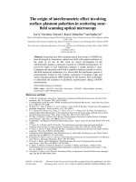
High resolution STM images of the HHB monolayers reveal the arrangement of
molecules within the monolayers. In Fig 6.3 the aromatic part of the HHB molecule –
the benzene rings appeared as brightest part in the STM image. The aliphatic dodecyl
groups appeared as dark part and could barely be observed. Although the atomic
resolution was not achieved, the shape of the bright part was able to help us to
determine the configuration of the HHB molecules on HOPG surfaces. The bright part
exhibited three ‘legs’, two pointing upwards and one pointing downwards. These
96
ADSORPTION-INDUCED CHIRAL SAMs
three ‘legs’ were assigned to the three carbazole groups. The molecular models of
HHB with benzene rings highlighted fit into the STM image very well.
N
N
N
Fig 6.3 Left: High resolution image of HHB monolayers: Bright hexagons represent the benzene
ring of HHB. Right: the molecular configuration of HHB (L-HHB) in monolayers. (V
bias
= 100mV,
and I
set
= 150pA)
The STM results showed that within that scanned area HHB molecule had only
one configuration: two carbazole groups on top and one carbazole group at the left
bottom, which we called it left-HHB (L-HHB). Its mirror image configuration with
two carbazole groups on top and one carbazole group at the right bottom (R-HHB)
was not observed within this scanned area. Therefore the monolayers were formed by
L-HHB and could be considered as chiral monolayers. Another STM images captured
in other region was shown in Fig 6.4. The resolution of this image is lower comparing
to Fig 6.3, especially for molecules at the boundary, because they had higher mobility
than the molecules at the center of the monolayers. In each molecule, top half was
brighter than rest part of molecule so it stood for two carbazole groups. The
97
ADSORPTION-INDUCED CHIRAL SAMs
brightness of bottom half is uneven, with right part being more intensive. This
suggested the molecule HHB’s configuration was mirror image of L-HHB, that is,
R-HHB. The monolayer formed by R-HHB was also a chiral monolayer.
Measurements of R-HHB monolayers and L-HHB showed that both unit cells were
rectangles with two sides at 3.900.80nm and 2.950.60nm.
N
N
N
Fig 6.4 Left: High resolution image of HHB monolayers: Bright hexagons represent the benzene
ring of HHB. Right: the molecular configuration of HHB (R-HHB) in monolayers. (V
bias
= 100mV,
and I
set
= 150pA)
6.3.3 Symmetry Transformation of SAMs
We regularly observed these two sets of domains with a reproducible small angle
relationship between the sets of 14.01.0 (Fig 6.5).
98
ADSORPTION-INDUCED CHIRAL SAMs
Fig 6.5 Top: STM image of two types of SAMs arrangement and their boundary. Bottom: The
surface plot of the STM image (current profile). The height of each pinnacle is proportional to the
magnitude of current. (V
bias
= 100mV, and I
set
= 150pA)
In the high-resolution image in Figure 6.5 the phenyl groups of molecule HBB
appear as regions of highest intensity, consistent with the occupied frontier orbitals
being localized on these sites. The contrast in STM images of organic molecules has
often been successfully compared to the frontier orbitals, either the HOMO or LUMO,
according to the polarity of the applied potential. In the STM images of HBB, the
aliphatic groups are harder to identify than the aromatic groups. The differences
between the left part and the right part of Figure 6.6 cannot be a consequence of
99
ADSORPTION-INDUCED CHIRAL SAMs
instrumental technique since they are from the same image. After using spectrum 2D
function to remove the noise, the differences between the left part and the right part
are apparent as shown in Fig 6.6: (i) the alignment of the individual molecules within
the rows and (ii) different ‘internal’ structure of the molecules. Further studies of the
SAMs showed that the unit cell on the right hand side is rectangular with two sides at
a=4.000.08nm and b=2.950.06nm. On the contrary, the unit cell on the left hand
side is rhombic with two sides at c=4.100.08nm, d=3.020.06nm respectively and
angle =761. It was observed that at the center bottom of the Fig 6.5 (highlighted
by black circle) the object did not match well with the neighbouring HHB molecules.
A surface plot of that region revealed that the tunneling current within the black circle
was higher than over the remaining part of the monolayers. It is however difficult to
determine the nature of the object directly from the STM image.
Fig 6.6 STM image of two types of SAMs arrangement and their boundary. Data was treated with
Spectrum 2D function. (V
bias
= 100mV, and I
set
= 150pA)
100
ADSORPTION-INDUCED CHIRAL SAMs
6.3 Discussion
6.3.1 STM Images of HHB
A large area scan of the HHB monolayers showed the monolayers started at the
steps of the HOPG surfaces (Fig 6.1). The molecules near the step are not as bright as
the molecules at the center of SAMs, but this is an artifact due to the hysteresis effect
of the STM when the tip moves across the steps. These bright dot arrays show that the
HHB molecules are localized firmly on the HOPG surfaces. On the contrary, in Fig
6.7 the molecules at the boundary are not as clear as the molecules at the center of the
SAMs because of their higher mobility. That suggests the steps assist the stabilization
of the molecules on the surface, which makes them the favorite physisorption sites on
the HOPG surfaces.
Fig 6.7 STM images of SAMs formed by HHB without presence of steps (V
bias
=100mV,
I
set
=50pA)
Furthermore, the SAMs formed not by the side of the steps are usually small in
lateral size (Fig 6.7) because the molecules at the SAMs’ boundary can easily move
101
ADSORPTION-INDUCED CHIRAL SAMs
away from the monolayers. The presence of rectangular unit cell of the monolayers
indicated that the structure and symmetry of the monolayers are mainly determined by
the interaction between the adsorbates rather than the substrate/adsorbates interactions,
since the arrangement of the unit cell do not follow the orientation of the graphite
surface lattice.
6.3.2 Chiral SAMs
In general, HHB is not planar, and its point group is being assigned as C
i
. This
group consists of only element E and hence does not contain an improper-rotation
axis. Therefore the molecule HHB is chiral. It was found that HHB was quite flat in
STM image, especially the aromatic moieties, allowing us to simplify HHB molecular
structure. The illustration of the physisorption process was shown in Fig 6.9, where
the HHB molecule is represented by a chiral center with three different attachments A,
B and C, which are not within the same plane.
Fig 6.8 Illustration of physisorption of HHB molecule onto HOPG surfaces
102
ADSORPTION-INDUCED CHIRAL SAMs
The physisorption process can be considered as an addition reaction between the
HHB and graphite surface, although no covalent bonds were formed. The resulting
products or the physisorbed molecules were shown in 1 and 2 when graphite attacked
HHB through route 1 (L-HHB) and 2 (R-HHB), respectively. As discussed in chapter
4 and chapter 5, the configurations of the adsorbates on the surface must be in such
way to maximize the intermolecular interaction between them. Similar to the system
in Chapter 4, the resulting monolayers are the thermodynamically stable products of
the physisorption process. In both L-HHB monolayers and R-HHB monolayers, the
molecules have to orientate in the same direction as the adsorbates physisorbed at an
early stage. Therefore the phase-separated chiral monolayers will form on the achiral
surfaces.
The proposed addition reaction mechanism is similar to the second step of an S
N
1
reaction. If the adsorbate has one side being blocked by bulky groups, the probability
for graphite attacking from the blocked site will be much lower than from the
unblocked site. In other words, the more open face of the adsorbates has a stronger
affinity towards the substrates. Based on the discussion, we may be able to synthesize
desired chiral monolayers simply by blocking one side of the adsorbates using bulky
groups.
6.3.3 Symmetry Transformation of SAMs
The shape of the unit cell of the HHB varied as shown in Fig 6.6 while the
orientation of the HHB did not change with it. The plane group of the unit cell
103
ADSORPTION-INDUCED CHIRAL SAMs
transformed from pg to p1 [32].
Detailed studies showed that the appearances of HBB under STM are different
for molecules on the left hand side and right hand side of the boundary (in black, Fig
6.7). The observation strongly suggested the ‘internal’ structures of molecules were
different within these two regions, although only near atomic resolution was achieved
during STM studies.
It was also noticed that at the boundary (Fig 6.6) there was a region with higher
tunneling current. This region could possibly be: a) overlap or mismatching of the
adsorbates; b) surface defects; c) impurities. It is quite difficult to identify the object
directly from the STM results. The sharp rise in current suggests it is more likely the
surface defects as the graphite has larger conductivity.
On the other hand, the unit cell of SAMs is a rectangle with two sides at
a=4.000.08nm and b=2.950.06nm, while the graphite has an in-plane lattice
constant of 2.46Å and a rhombic unit cell with angle equals to 60°. The mismatch
between the monolayers and substrate can possibly lead to transformation of SAMs
unit cell. Therefore the change of the symmetry group of SAMs unit cell was possibly
caused by i) the presence of the unknown object; ii) incommensurate lattice constant
between the graphite and SAMs. The monolayers conformation was sensitive to the
substrate structure.
104
ADSORPTION-INDUCED CHIRAL SAMs
6.4 Conclusion
An ordered monolayer formed from the hexaalkyl hexaphenylbenzene (HHB) on
an HOPG substrate is imaged by STM. Analysis of the STM images shows that the
molecules form chiral monolayers on the HOPG surfaces. The chirality of the SAMs
is due to the different binding sites that the adsorbates can have upon physisorption
onto HOPG. The existence of phase separated chiral monolayers also indicated the
physisorbed monolayers were the thermodynamically stable products of self-assembly
process. Formation of desired chiral surface is made possible using the self-assembled
technique. Meanwhile, we noticed that the monolayers unit cell was transformed
within certain regions, possibly due to the presence of the surface defects or
incommensurability between the SAMs and substrate.
105
ADSORPTION-INDUCED CHIRAL SAMs
Reference
[1] Pasteur, L. C.R. Seances. Acad. Scie. 1848, 26, 535.
[2] Wan, K.T.; Davis, M.E. Nature 1994, 370, 449.
[3] Blaser, H.U. Tetrahedron: Asym. 1991, 2, 843.
[4] Lorenzo, M. O.; Baddeley, C. J.; Muryn, C.; Raval, R. Nature 2000, 404, 376.
[5] Switzer, J. A.; Kothari, H. M.; Poizot, P.; Nakanishi, S.; Bohannan, E. W. Nature
2003, 425, 490.
[6] Eckhardt, C. J.; Peachey, N. M.; Swanson, D. R.; Takacs, J. M.; Khan, M.A.;
Gong, X.; Kim, J H.; Uphaus, R. A. Nature 1993, 362, 614.
[7] Stevens, F.; Dyer, D. J.; Walba, D. M. Angew. Chem., Int. Ed. Engl. 1996, 35, 900.
[8] Fang, H.; Giancarlo, L. C.; Flynn, G. W. J. Phys. Chem. B 1998, 102, 7311.
[9] Viswanathan, R.; Zasadzinski, J. A.; Schwartz, D. K. Nature 1994, 368, 440.
[10] Weckesser, J.; De Vita, A.; Barth, J. V.; Cai, J.; Kern, K. Phys. Rev. Lett. 2001, 87,
096101.
[11] Lorenzo, M. O.; Haq, S.; Bertrams, T.; Murray, P.; Raval, R.; Baddeley, C. J. J.
Phys. Chem. B 1999, 103, 10661.
[12] Charra, F.; Cousty, J. Phys. Rev. Lett. 1998, 80, 1682.
[13] Cai, Y.; Bernasek, S. L. J. Am. Chem. Soc. 2003, 125, 1655.
[14] Li, C. J.; Zeng, Q. D.; Wu, P.; Xu, S. L.; Wang, C.; Qiao, Y. H.; Wan, L. J.; Bai, C.
L. J. Phys. Chem. B 2002, 106, 13262.
[15] Yablon, D. G.; Guo, J. S.; Knapp, D.; Fang, H. B.; Flynn, G. W. J. Phys. Chem. B
2001, 105, 4313.
106
ADSORPTION-INDUCED CHIRAL SAMs
[16]. Lopinski, G. P.; Moffatt, D. J.; Wayner, D. D. M.; Wolkow, R. A. Nature 1998,
392, 909.
[17] Qian, P.; Nanjo, H.; Yokoyama, T.; Suzuki, T. M. Chem. Commun. 1999, 13,
1197.
[18] Sholl, D. S.; Asthagiri, A.; Power, T. D. J. Phys. Chem. B 2001, 105, 4771.
[19] Kuhnle, A.; Linderoth, T. R.; Hammer, B.; Besenbacher, F. Nature 2002, 415,
891.
[20] Orme, C. A.; Noy, A.; Wierzbicki, A.; McBride, M. T.; Grantham, M.; Teng, H.
H.; Dove, P. M.; DeYoreo, J. J. Nature 2001, 411, 775.
[21] Yablon, D. G.; Giancarlo, L. C. Flynn, G. W. J. Phys. Chem. B 2000, 104, 7627.
[22] Yablon, D. G.; Wintgen, D.; Flynn, G. W. J. Phys. Chem. B 2002, 106, 5470.
[23] Hibino, M.; Sumi, A.; Tsuchiya, H.; Hatta, I. J. Phys. Chem. B 1998, 102, 4544.
[24] Kim, B. Y.; Cai, C.; Deng, X.; Perry, S. S. Surf. Sci. 2003, 538, 45.
[25] Chen, Q.; Frankel, D. J.; Richardson, N. V. Surf. Sci. 2002, 497, 37.
[26] Eckhardt, C. J.; Peachey, N. M.; Swanson, D. R.; Takacs, J. M.;Khan, M. A.;
Gong, X.; Kim, J H.; Wang, J.; Uphaus, R. A. Nature 1993,362, 614.
[27] Walba, D. M.; Stevens, F.; Clark, N. A.; Parks, D. C. Acc. Chem. Res. 1996, 29,
591.
[28] Bohringer, M.; Morgenstern, K.; Schneider, W.; Berndt, R. Angew. Chem., Int. Ed.
Engl. 1999, 38, 821.
[29] Chandrasekhar, S.; Sadashiva, B.K.; Suresh, K.A. Pramana, 1977, 9, 471.
[30] Boden, N.; Bushby, R.J.; Clements, J.; Jesudason, M.V.; Knowles, P.F.; Williams,
107
ADSORPTION-INDUCED CHIRAL SAMs
108
G. Chem. Phys. Lett. 1988, 152, 94.
[31] Adam, D.; Closs, F.; Frey, T.; Funhoff, D.; Haarer, D.; Ringsdorf, H.;
Schuhmacher, P.; Siemensmeyer, K.; Phys. Rev. Lett. 1993, 70, 457.
[32] Plass, K. E.; Grzesiak, A. L., Matzger, A. J. Acc. Chem. Res. 2007, 40, 287.