Chapter 2 literature review design and development of tissue engineering scafflods using rapid prototyping technology
Bạn đang xem bản rút gọn của tài liệu. Xem và tải ngay bản đầy đủ của tài liệu tại đây (435.75 KB, 44 trang )
Chapter Two: Literature Review
Chapter Two
Literature Review
10
Chapter Two: Literature Review
2.1 Tissue Engineering Scaffolds
By far tissue engineering strategy that involves cell transplantation has shown
high potential in treating damaged or malfunctioning organs. Because of the
fact that many cell types are anchorage-dependent, their direct transplantation
in the recipient’s body might result in death or loss of function and thus require
the presence of a substrate. It has also been observed that dissociated cells
tend to organize themselves to form a tissue structure when they are provided
with a proper guiding template (Vacanti et al, 1998). Therefore, the modern
tissue engineering approach utilizes three-dimensional porous scaffolds made
of natural or synthetic polymers which provide temporary substrate for cell
attachment, proliferation and function.
The key parameters in designing a suitable scaffold for tissue engineering
applications include the material properties and the macro/micro structure of
the scaffolds (i.e. porosity and pore morphology). An interconnected internal
structure of the scaffold is important for adequate flow of nutrients into and
transport of metabolic waste out of the structure (Langer and Vacanti, 1993).
The scaffold materials must be biocompatible which means they must not
trigger any adverse reactions with tissues. Surface properties of the scaffold
are also important for proper attachment of the cells onto the structure. Often,
additives such as hydroxyapatite (HA) are added to the basic scaffolding
material to promote cell attachment. In case of tissues that are subjected to
stress and strain, e.g. arteries, heart valves, bones etc. the scaffold matrix must
provide sufficient mechanical strength to withstand in vivo stresses and loading.
The mechanical properties of the bioresorbable 3D scaffold/tissue construct at
11
Chapter Two: Literature Review
the time of implantation should match that of the host tissue as closely as
possible. Lastly, the scaffold material is expected to be reabsorbed by the
tissue after the cells have established themselves. Hence, the scaffold material
should essentially be selected and/or designed with a controlled degradation
and resorption rate such that the strength of the scaffold is retained until the
tissue engineered transplant is fully accommodated by the host tissue and can
assume its structural role (Stephen et al, 1998).
2.2 Scaffold Materials
One of the fundamental issues with regard to tissue engineering is the choice of
suitable material. Currently, polymeric materials have drawn great attention
from the scientific and medical communities for tissue engineering applications
(Maquet et al, 1997). Natural polymers such as collagens, glycosaminoglycan,
starch, chitin and chitosan have been used to repair nerves, skin, cartilage, and
bone (Mano et al, 1999). These naturally occurring biomaterials might most
closely simulate the native cellular milieu. However, large batch-to-batch
variation upon isolation from biological tissues and availability are the main
limitations for their wide applications. Poor mechanical performance is also a
drawback for transplanted scaffolds made from natural polymers. On top of that
natural polymers such as collagen and gylcosaminoglycan could also provoke
adverse tissue reactions and immune responses.
Synthetic polymers have been developed to overcome the aforementioned
problems associated with natural polymers. Synthetic polymers are well known
for their enormous availability, high processability, and controllable mechanical
12
Chapter Two: Literature Review
and biochemical properties. Most synthetic polymers degrade via chemical
hydrolysis and insensitive to enzymatic processes so that their degradation
behaviours do not vary from patient to patient. Many synthetic bioresorbable
polymers such as poly (α-hydroxy ester)s, polyanhydrides, polyorthoesters,
and polyphosphazens, have been studied for temporary surgical and
pharmacological applications (Vert et al, 1992; Pitt et al, 1981a). These
polymers have been found to be suitable to construct bioresorbable 3D
scaffolds for tissue engineering applications. Properties of different synthetic
polymers are summarized in Table 2.1.
Table 2.1: Properties of Biodegradable Polymers (Shalaby et al, 1994; Maquet
et al, 1997; Perrin and English, 1997; Middleton et al, 1998; Ali and Hamid,
1998; Huang Ming-Hsi et al, 2003;
)
Polymer
Type
Melting
Point
(°C)
Glass
Transi
tion
Temp
(°C)
Degra
dation
Time
(months)
a
Density
(g/cc)
Tensile
Strength
(MPA)
Elonga
tion %
Modu
lus (GPA)
PLGA Amor
phous
45-55 6-12 1.27-
1.34
41.4-55.2 3-10 1.4-2.8
DL-PLA Amor
phous
55-60 12-16 1.25 27.6-41.4 3-10 1.4-2.8
L-PLA 173-178 60-65 >24 1.24 55.2-82.7 5-10 2.8-4.2
PGA 185-225 25-65 6-12 1.53 >68.9 15-20 >6.9
PCL 58-68 - 70 >24 1.11 20.7-34.5 300-500 0.21-0.34
PEG 67-69 - 72 - 1.05 - - -
PCL-PLA 61-68 - 55 - - - - -
PCL-PEG 60-67 - 69 - - - - -
PCL-PEG-P
CL
59-69 - 69 - - - - -
PLA-PCL-P
LA
58-67 - 67 - - - - -
PEG-PCL-P
LA
58-65 - 68 - - - - -
a
Time to complete mass loss. Time also depends on part geometry.
13
Chapter Two: Literature Review
2.2.1 Poly(ε-Caprolactone)
Poly (ε-caprolactone) is one of the earliest polymers synthesised by the
Carothers group in the early 1930s (van Natta et al, 1934). Commercially it
became available following efforts to identify synthetic polymers that could be
degraded by micro-organisms. Poly (caprolactone) can be prepared by either
ring-opening polymerisation of caprolactone using a variety of anionic, cationic
and coordination catalysts or via free radical ring-opening polymerisation of
2-methylene-1-3-dioxepane. Poly (caprolactone) is a semicrystalline polymer.
This semi-crystalline, linear aliphatic polyester has a repeating molecular unit of
five non-polar methylene groups and a single relatively polar ester group
(Figure 2.1). Its crystallinity tends to decrease with increasing molecular weight.
Degradation occurs largely due to the presence of the hydrolytically unstable
aliphatic-ester linkages.
Figure 2.1: Repeating molecular structure of PCL
The high solubility of poly (caprolactone), its low melting point (59 to 64
o
C) and
exceptional ability to form blends has stimulated research on its application as a
biomaterial. In 1981 Pitt and co-workers (Pitt et al, 1981b) first reported an in
vivo study of PCL drug-delivery capsules in a rabbit model. It was observed
that the polymer degraded in a two-phase process, with the majority of
molecular weight loss occurring primarily in the first phase, and the subsequent
14
Chapter Two: Literature Review
loss in mass and strength beginning at the onset of the second phase at an
average molecular weight of 5000.
PCL was susceptible to both enzymatic and non-enzymatic degradation.
Woodward and co-workers (Woodward et al, 1985) studied the intracellular
degradation of low molecular weight (Mn 3000) PCL powders (106 to 500 µm)
in rats. They reported that the PCL powders were hydrolytically degraded in
phagosomes secreted by macrophages and giant cells. Their studies
suggested that in an in-vivo environment, enzyme-mediated intracellular
degradation might be the principal pathway of degradation once the polymer
was sufficiently pre-degraded by earlier non-enzymatic bulk hydrolysis.
Degradation of PCL preceded by random hydrolytic chain scission of the ester
linkages, eventually producing the monomeric hydroxyacid. Pitt (1992) also
reported that in rat PCL was metabolized to ε-hydroxycaproic acid, the end
product of ester hydrolysis in vivo. The hydroxyacid was respired and broken
down to CO
2
and H
2
O when exposed to tissue fluids (Pitt et al, 1979).
Poly (caprolactone) has slow degradation and resorption kinetics and can
therefore be used in drug delivery devices that remain active for over one year.
The toxicology of PCL had been extensively studied as part of the evaluation of
Capronor
TM
, a one-year implantable subdermal contraceptive device as
reported by Darney et al (1989) and Ory et al (1983). Based on these clinical
products, ε-caprolactone and PCL were regarded as non-toxic and hard and
soft tissue compatible materials. Capronor had undergone FDA-approved
phase I and II clinical trials (Pitt, 1990). Extensive in-vitro and in-vivo
15
Chapter Two: Literature Review
biocompatibility and efficacy studies had also been performed in the research
leading to the introduction of the Monocryl
TM
monofilament sutures as reported
by Bezwada et al (1995).
Several researchers (Hutmacher et al, 2000a; Marra et al, 1999a; Corden et al,
2000) could show the good biocompatibility of two-dimensional PCL specimens
in human osteoblast-like cell cultures. Marra et al (1999a) concluded from their
2-D cell studies that PCL is superior to PLGA for bone cell growth. Cell
migration requires a biomolecular healthy and dynamic interaction among the
cell, scaffold surface and its cytoskeleton. Human osteoblast-like cell culture
data showed the evidence of good biocompatibility of PCL for hard tissue
formation.
Among the bioresorbable polymers used for biomedical applications, PCL has
an unusually low glass transition temperature (T
g
) of – 65°C. It also has a low
melting temperature of 59-64°C and exists in a rubbery state at room
temperature. Another unusual property of PCL is its high thermal stability. It
has a much higher decomposition temperature (Td) of 350°C, in compared to
other tested aliphatic polyesters that have decomposition temperatures (Td)
between 235 and 255°C (Suggs and Mikos, 1996). Solid PCL also exhibits
moderate mechanical properties as shown in Table 2.1. In comparison to other
commercially available bioresorbable polymers, PCL is one of the most flexible
and easy to process materials. Even though it has one of the slowest
degradation rates of all such polymers, the structural stability of PCL permits
the study of fabrication and characterization as a tissue engineering scaffold.
16
Chapter Two: Literature Review
2.2.2 Copolymers
Presently, PCL is regarded as a soft- and hard-tissue compatible
biodegradable material and often selected as a suitable material for
thermoplastic processing of scaffolds for tissue engineering (Perrin and
English, 1998a). The first generation of bioresorbable scaffolds for
tissue-engineering applications has been fabricated from synthetic polymers of
the aliphatic polyester family (Hutmacher et al, 2000a; Vats et al, 2003).
However, the number of such bioresorbable polymers is limited when polymers
with different properties are needed for the design and fabrication of devices
and scaffolds adapted to specific applications (Hutmacher, 2001a; Saltzman,
1999). Polymers such as poly(ethylene glycol) (PEG), poly(ε-caprolactone)
(PCL) and poly(DL-lactide) (P(DL)LA) have been used to make in vivo
degradable medical and drug-delivery devices with Food and Drug
Administration approval (Pitt, 1990; Li and Vert, 1999). Polyester–polyether
block co-polymers composed of PCL or PLA and PEG have been considered
as suitable because they offer possibilities to vary the ratio of
hydrophobic/hydrophilic constituents by copolymerization and to modulate
degradability and hydrophilicity of corresponding matrices and surfaces
(Rashkov et al, 1996; Li et al, 2002). Despite of favorable rheological properties
and thermal stability in molten state, PCL degrades very slowly due to its high
hydrophobicity and crystallinity (Pitt, 1990; Moore and Saunders, 1997).
Introduction of hydrophilic blocks and/or fast degrading blocks into PCL main
chains can be a means to prepare novel degradable and bioresorbable
polymers. Hydrophilic polyether blocks such as poly(ethylene glycol) (PEG) are
introduced into PCL chains to enhance the hydrophilicity of the parent PCL
17
Chapter Two: Literature Review
homo-polymer (Li et al, 2002; Lee et al, 2001). Likewise, block
co-polymerization of PCL with faster degrading polyesters, such as
poly(lactide) (PLA), allows to modify the degradability of the parent PCL
homo-polymer (Feng et al, 1983; Deng et al, 1997). However, both types of
co-polymers present specific disadvantages. PLA is a hydrophobic polymer,
whereas PEG is hydrophilic but not degradable in vivo. Therefore, PCL-based
co-polymer (PEG-PCL-PLA) was synthesized by combining both PEG and PLA
blocks with PCL chains to produce novel hydrophilic and bioresorbable
co-polymer with the aim of enhancing hydrophilicity and degradability.
Similarly, if ε-caprolactone is copolymerised with ethylene oxide (EO) or
poly(ethylene glycol) (PEG) to prepare PCL/PEG(PEO) block copolymers, their
physical property, hydrophilicity and biodegradability can also be improved, and
thus they may find much wider applications. Recently, several research groups
(Nagasaki et al, 1998; Li et al, 1996; Kricheldorf et al, 1993; Yuan et al, 2000;
Dobrzynski et al, 1999; Longhai et al, 2003; Huang et al, 2004) prepared
bioresorbable polyester–PEG diblock or triblock copolymers by using a
monohydroxy or α,ω-dihydroxy PEG as initiator for the polymerization of
lactone monomers employing various techniques. Longhai et al (2003)
synthesized and characterized the PCL-PEG-PCL triblock copolymers by
ring-opening polymerization of ε-caprolactone (CL) in the presence of
poly(ethylene glycol) using calcium catalyst. The differential scanning
calorimetry and wide-angle X-ray diffraction analyses revealed the
micro-domain structure in the copolymer. The melting temperature, Tm and
crystallization temperature, Tc of the PEG domain were observed to be
18
Chapter Two: Literature Review
influenced by the relative length of the PCL blocks. They mentioned that it was
because of the strong covalent interconnection between the two domains.
Huang et al (2004) performed degradation and cell culture studies on PCL
homopolymer and PCL/PEG diblock and triblock copolymers prepared by
ring-opening polymerization of ε-caprolactone in the presence of ethylene
glycol or PEG using zinc metal as catalyst. They performed the degradation of
PCL and PCL/PEG diblock and triblock copolymers in a 0.13 M, pH 7.4
phosphate buffer at 37
0
C. The results indicated that the copolymers exhibited
higher hydrophilicity and degradability compared to the PCL homopolymer.
They cultured primary human and rat bone marrow derived stromal cells
(hMSC, rMSC) on the scaffolds manufactured with PCL homopolymer and
PCL/PEG diblock and triblock copolymers via solid free form fabrication. Light,
scanning electron and confocal laser microscopy as well as
immunocytochemistry showed cell attachment, proliferation and extracellular
matrix production on the surfaces along with inside the scaffold architectures of
all polymers. However, the copolymers showed better performance in the cell
culture studies than the PCL homopolymer.
Some other researchers investigated the block-copolymers poly(ethylene
glycol)-terephthalate/poly(butylene terephthalate) (PEGT/PBT) and
polyethyleneoxide-terephtalate /polybutylene-terephtelate ((PEOT/PBT) to
process into 3D scaffolds that can modulate their viscoelastic properties in
order to mimic a large collection of natural tissues (Woodfield et al, 2004;
Moroni et al, 2006). These polyether-ester multiblock copolymers belong to a
class of materials known as thermoplastic elastomers that exhibit good physical
19
Chapter Two: Literature Review
properties like elasticity, toughness and strength in combination with easy
processability (Bezemer et al, 1999). This family of copolymers has drawn
great attention for tissue engineering and drug delivery applications, because
by varying the molecular weight of the starting poly(ethylene glycol) (PEG)
segments and the weight ratio of PEOT and PBT blocks it is possible to
tailor-make properties, such as wettability (Olde et al, 2003), swelling
(Bezemer et al, 1999; van Dijkhuizen-Radersma et al, 2002; Deschamps et al,
2002) [26,28,29], biodegradation rate (Deschamps et al, 2002), protein
adsorption (Mahmood et al, 2004) and mechanical properties (Woodfield et al,
2004). Furthermore, PEOT/PBT block copolymers have shown to be
extensively biocompatible both in vitro and in vivo (van Blitterswijk et al, 1993;
Beumer et al, 1994) and reached clinical applications (PolyActiveTM, IsoTis
Orthopaedics S.A.) as cement stoppers and bone fillers in orthopedic surgery
(Mensik et al, 2002; Bulstra et al, 1996). Being polyether-esters, degradation
occurs in aqueous media by hydrolysis and oxidation, the rate of which varying
from very slow for high PBT contents to medium and fast for larger contents of
PEOT and longer PEO segments (Bezemer et al, 1999; Deschamps et al,
2002).
2.3 Structures and Properties
The second important issue to be addressed in tissue engineering is the macro-
and microstructures of the scaffolds. From materials engineering point of view,
tissues are considered to be cellular composites representing multiphase
systems. Cellular composites are then seen as consisting of three main
structural components: (1) cells that are organized into functional units, (2)
20
Chapter Two: Literature Review
extracellular matrix, and (3) scaffold architecture. This architecture is
increasingly believed to contribute significantly to the development of specific
biological functions in tissues and thought to provide appropriate nutritional
conditions and spatial organization for cell growth. The regeneration of specific
tissues aided by synthetic materials has been shown to be dependent on the
porosity and pore size of the supporting three-dimensional structure (Cima et
al, 1991). A large surface area favours cell attachment and growth, whereas a
large pore volume is required to accommodate and subsequently deliver a cell
mass sufficient for tissue repair. Clinically approved synthetic bioresorbable
polymers were primarily considered as the material of choice to build such
porous three-dimensional (3D) scaffolds. It is important to recognize some of
the salient features of porous solids to understand how a scaffold design could
affect its physical and mechanical properties. In tissue engineering
applications, scaffolds require a balance of high inter-connectivity of pores (3D
internal architecture) with overall structural stability (mechanical
characteristics). Porous solids consisted of different types of natural and
synthetic materials are generally classified as honeycombs and foams (Gibson
and Ashby, 1997).
2.3.1 Honeycombs and Foams
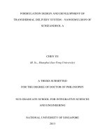
A honeycomb consists of a regular two-dimensional array of polygonal pores
each defined by a wall shared between adjacent pores. The pores are packed
to fill a plane area like the hexagonal cells of the bee’s honeycomb. Figures
2.2a–d show the structural plan-views of synthetic honeycombs with
hexagonal, triangular and square pores, otherwise known as two-dimensional
porous materials. On the other hand, foam has a structure in which polyhedral
21
Chapter Two: Literature Review
pores are surrounded by faces or edges, and are packed in 3D to fill space.
Figures 2.2e – f illustrate both polymeric foams, termed as three-dimensional
porous materials, with open and closed pores.
According to the ASTM terminology (American Standard, 1999) pores are
classified into three groups: interconnecting (open pores), non-connecting
(closed pores), or a combination of both. When the pores are open, the foam
material is usually drawn into struts forming the pore edges (Figure 2.2e). A
network of struts produces a low-density solid with pores connecting to each
other through open faces. When the pores are closed, a network of
interconnected plates produces a higher-density solid. The virtually closed
pores are sealed off from adjacent neighbours (Figure 2.2f).
a b
c d
e f
Figure 2.2: Porous materials: (a) 2D aluminium honeycomb, (b) 2D
paper-phenolic resin honeycomb, (c) 2D ceramic honeycomb with square
pores, (d) 2D ceramic honeycomb with triangular pores, (e) 3D open-pore
polyurethane, (f) 3D closed-pore polyethylene (Gibson and Ashby, 1997)
2.3.2 Mechanical Properties
In tissue engineering applications, porous scaffolds must have sufficient
mechanical strength to retain their initial structures after implantation,
particularly in the reconstruction of hard, load-bearing tissues, such as bones
and cartilages. The structure must not collapse or compress together under
22
Chapter Two: Literature Review
pressure, causing damage to the cells within. The biostability of many implants
depends on factors such as strength, elasticity, absorption at the material
interface and chemical degradation. Therefore, the investigation of
compressive properties is of primary importance in determining the suitability of
the designed scaffold. Other mechanical properties like, tensile or flexural
properties are secondary to the compressive properties for some basic
reasons. Firstly, it should be considered that at the end the scaffolds would be
utilized in the physiological environment where the primary loading is
compressive e.g. bone or cartilage. Secondly, the presence of numerous tiny
voids in the porous solid poses significant structural flaws to magnify the effect
of crack propagation in stretching or bending. In addition, the specimen
specification for tensile (dog bone shape) or flexural test is also a limiting factor
as it often remains tedious to prepare the scaffold samples accordingly.
Therefore, the majority of research findings on tissue engineering scaffolds had
been focused on their compressive properties when reporting on scaffolds
mechanical properties. Most formulations, as reviewed by Gibson and Ashby
(1997), found that the mechanical properties of a porous solid depended mainly
on its relative density, the properties of the material that made up the pore
edges or walls and the anisotropic nature, if any, of the solid. Figure 2.3
represents the model of a honeycomb and an open-pore foam.
23
Chapter Two: Literature Review
(a)
(b)
Figure 2.3: (a) Honeycomb with prismatic hexagonal pores (b) Cubic model for
an open-pore foam showing the edge length l and the edge thickness t (Gibson
and Ashby, 1997)
The deformation behaviours of porous solids under compressive loads for
honeycombs are shown in Figures 2.4 and 2.5. The mechanical properties of
honeycombs are classified in two groups: in-plane properties and out-of-plane
properties. The in-plane properties are those relating to loads applied in the X
1
– X
2
plane. Responses to loads applied to the faces normal to X
3
are referred
to as out-of-plane properties.
(a)
(c)
(b)
Figure 2.4: In-plane compression of honeycomb pores; (a) Initial elastic
bending of pore walls, (b) Buckling of pore edges at higher stress levels and (c)
Out-of plane compression of honeycomb pores (Gibson and Ashby, 1997)
24
Chapter Two: Literature Review
(b)
(a)
Figure 2.5: A schematic diagram for a honeycomb loaded in compression,
showing linear elastic, collapse and densification regimes, and the way the
stress-strain curves changes with t/l; (a) compressed in X
1
– X
2
plane, (b)
compressed in axial (X
3
) direction (Gibson and Ashby, 1997)
When a honeycomb is compressed in-plane, the pore walls at first bend (Figure
2.4a), giving linear elastic deformation (shown on stress-strain curves in Figure
2.5a). Beyond a critical strain the pores collapse by elastic buckling, plastic
yielding (Figure 2.4b), creep or brittle fracture, depending on the nature of the
pore wall material. Pore collapse ends once the opposing pore walls begin to
touch each other; as the pores close up the structure is densified and its
stiffness increases rapidly. On loading the honeycomb out-of-plane, the pore
walls experience compression under both axial and bending stresses. The
moduli and collapse stresses are much larger. Figure 2.5b shows the family of
curves of honeycombs with different relative density (∝ t/l), compressed
out-of-plane.
The deformation behaviours of porous solids under compressive loads for
open-pore foams are shown in Figures 2.6. Like honeycombs, foams (Figure
25
Chapter Two: Literature Review
2.6 a & b) also show linear elasticity (Figure2.6c) at low stresses followed by a
long collapse plateau during which the pore edges buckle (Figure 2.6b). This
is truncated by a final regime of densification in which the stress rises steeply
when the pores are completely collapsed. Experimental results, checked by
using honeycombs (Patel and Finnie, 1970; Abd El-Sayed et al, 1979; Warren
and Kraynik, 1987) and foams (Patel and Finnie, 1970; Menges and Knipschild,
1975; Warren and Kraynik, 1988) with a wide range of materials, structures and
density, have been reported to produce good agreements in general.
(a) (b) (c)
Figure 2.6: Deformation behaviour of an open-pore foam; (a) Pore edge
bending, (b) Pore edge buckling, (c) Schematic compressive stress-strain
curve, showing the three regimes of linear elasticity, collapse and densification
(Gibson and Ashby, 1997).
2.4 Scaffold Fabrication Techniques
2.4.1 Basic Requirements
Besides the material issues (non-mutagenic, non-antigenic, non-carcinogenic,
non-toxic, non-teratogenic), it is of major importance in scaffold production to
maintain sufficient accuracy over the macro- (e.g., spatial form, mechanical
strength, density, porosity) and microstructural (e.g., pore size, pore
distribution, pore interconnectivity) properties. A large variety of natural or
26
Chapter Two: Literature Review
synthetic scaffolding materials have been developed depending on the
targeted tissue. Each scaffolding material or combination of materials
possesses different processing requirements and varying degrees of
processability to form scaffolds. The key requirements necessary to assess a
fabrication technique for scaffold production include the followings (Leong et al,
2003a):
Processing Conditions: The material properties of the scaffolds should not be
adversely affected by the material processing procedures and conditions. This
means the technique should not change the chemical properties and
biocompatibility of the scaffold nor cause any deterioration in its mechanical
properties.
Process Accuracy: The technique should produce spatially and anatomically
accurate three-dimensional scaffolds that fit the intended spaces at the implant
site. The capability to vary and maintain accurate pore sizes and morphologies
will enable a wide variety of scaffolds to be produced to suit different targeted
TE applications. Accuracy in construction of scaffolds will enable the
application of computer-aided engineering (CAE) methods to perform strength
and degradation analyses to predict the scaffolds’ performance. By this means,
optimized scaffold designs can be realized with minimal experimentation.
Consistency: The technique should be able to produce scaffold with highly
consistent pore sizes with a narrow range of size distribution over the entire
volume. Consistency in pore size, shape, distribution, density and
interconnectivity in all three dimensions is required to produce highly regular
three-dimensional structures.
27
Chapter Two: Literature Review
Repeatability: The same set of processing parameters and conditions should
exhibit minimal variations in physical forms and properties of different scaffold
batches. The technique should also allow achieving highly consistent and
reproducible results without encountering any major difficulty.
2.4.2 Limitations of Conventional Techniques
Conventional scaffold fabrication techniques have been developed mainly on
the basis of textile and polymer processing technologies. These techniques
include non-weaving (Ma and Langer, 1995), fibre bonding (Wang et al, 1993;
Brauker et al, 1995), phase separation (Lo et al, 1995; Ma and Zhang, 1999),
solvent casting/particulate leaching (Mikos et al, 1993b; Holy et al, 2000),
membrane lamination (Mikos et al, 1996), melt moulding (Thomson et al,
1995a), gas foaming/high pressure processing (Baldwin et al, 1995; Mooney et
al 1996), hydrocarbon templating (Shastri et al, 2000), freeze drying (Whang et
al, 1995; Healy et al, 1998) and combinations of these techniques (e.g., gas
foaming/particulate leaching (Harris et al, 1998), etc.). The working principles,
procedures, applications and potentials of these techniques can be found in
several other works (Vacanti et al, 1988; Widmer and Mikos, 1998; Thomson et
al, 2000; Yang et al, 2001; Sachlos and Czernuszka, 2003). To date
conventional techniques have shown great promise in the scaffold fabrication
and a wide range of scaffold characteristics, such as porosity, pore size etc.
have been reported (Widmer and Mikos, 1998; Hutmacher, 2000b). However,
these techniques remain impractical to manufacture scaffolds as required
because of a number of limitations. They are as follows (Leong et al, 2003a):
28
Chapter Two: Literature Review
Manual Intervention: All conventional techniques involve multi-stage manual
processes that are labour-intensive and time-consuming. For example,
particulate leaching involves mixing of salt(s) with the scaffold material, casting
the object and further dissolving the salt(s) to produce porous scaffold. The
system heavily relies on user skills and experiences and thus often results in
non-uniformity and poor repeatability of the scaffold architectures and
properties.
Reproducibility of Processing Procedures: Conventional techniques are
unable to precisely control the pore size, pore geometry and spatial distribution
of pores which results in inconsistent macro- and micro-structure of the
scaffolds. Scaffolds produced by solvent-casting and/or particulate-leaching
cannot guarantee interconnection of pores because this is dependent on
whether the adjacent salt particles are in contact.
Use of Toxic Solvents: Most conventional techniques require extensive use of
toxic organic solvents to dissolve the raw stock (granules, pellets or powders)
and convert into the final scaffold. Thereupon, it becomes difficult to remove the
toxic solvents completely from the fabricated scaffolds especially, in thicker
constructs. The residual toxic solvents cause adverse effects on adherent cells,
incorporated biological active agents or nearby tissues (Healy et al, 1998).
Use of Porogens: Some techniques (e.g., particulate leaching, hydrocarbon
templating, etc.) utilize salts or waxes as porogens to create porosities in the
scaffolds. The use of porogens limits the scaffold thickness to approximately
29
Chapter Two: Literature Review
2mm (Lu and Mikos, 1996) because of the problems in complete removal of
porogens. In addition, it becomes difficult to prevent the agglomeration of
porogen particles and thus to achieve uniform porogen dispersion. This
phenomenon results in uneven pore size and densities, and morphologies of
the scaffolds which give rise to anisotropy in scaffold properties (Hutmacher et
al, 2001b).
Shape Limitation: Some of the techniques use moulds or containers to
manufacture scaffold as thin membranes or three-dimensional constructs.
These techniques are confined to create certain simple shapes and cannot
produce scaffolds with complex and desired structural architectures.
Limited Cell Growth: Conventional techniques produce scaffolds mostly in the
form of foams. Cells are then seeded and expected to grow into the scaffold.
However, this approach has resulted in the in vitro growth of tissues with
cross-sections of less than 500µm from the external surface (Ishaug-Riley et al,
1997; Freed and Vunjak-Novakovic, 1998). This is probably due to the diffusion
constraint of the foam which causes scarcity in nutrients and oxygen supply,
and insufficient removal of waste products.
30
Chapter Two: Literature Review
Table 2.2: Summary of the advantages and disadvantages of conventional
scaffold fabrication techniques (Leong et al, 2003a)
Process Advantages Disadvantages
Textile technique
Larger pores and high
porosity
Structurally unstable and lacking in
mechanical properties
Fibre bonding Easy process, high porosity
and high surface area to
volume ratio
High processing temperature for
non-amorphous polymer, limited range of
polymers, lack of mechanical strength,
poor control over micro-architecture,
problems with residual solvent
Phase separation
Highly porous structures,
allows incorporation of
bioactive agents
Lack of control over micro-architecture,
limited range of pore sizes, problems with
residual solvent
Solvent casting
and particulate
leaching
Highly porous structures,
large range of pore sizes,
Independent control of
porosity and pore size,
crystallinity can be tailored
Limited membrane thickness, lack of
mechanical strength, problems with
residual solvent and residual porogens
Membrane
lamination
Macro shape control,
independent control of
porosity and pore size,
Lack of mechanical strength, problems
with residual solvent, tedious and
time-consuming procedure, limited
interconnected pores
Melt moulding
Independent control of
porosity and pore size,
Macro shape control
High processing temperature for
non-amorphous polymer, Residual
porogens
Polymer/ceramic
fibre composite
foam
Good compressive strength,
Independent control of
porosity and pore size
Problems with residual solvent and
residual porogens
High-pressure
processing and
particulate
leaching
Highly porous structures,
organic solvent free, Allows
incorporation of bioactive
agents, Independent control
of porosity and pore size
Limited interconnected pores, Residual
porogens
Freeze drying Highly porous structures
High pore interconnectivity
Limited to small pore sizes
Hydrocarbon
templating
No thickness limitation,
independent control of
porosity and pore size
Problems with residual solvent and
Residual porogens
31
Chapter Two: Literature Review
2.4.3 RP Techniques
The inherent limitations of the conventional methods have led to use the rapid
prototyping (RP) techniques to customize design and fabricate porous scaffolds
with fully interconnected pore networks. Rapid prototyping (RP) is the name
given to a host of related technologies that are used to fabricate physical
objects directly from computer aided design (CAD) data sources. Such systems
are also known by the general names free form fabrication (FFF), solid free
form (SFF) fabrication or layered manufacturing (LM) (Pham and Gault, 1998)
because of the fact that this technique does not use any mould to fabricate the
object. Unlike conventional machining which involves constant removal of
materials, RP is an additive process. The underlying concept of RP technique is
the generation of parts by selectively adding materials layer-by-layer through a
process that deposits, bonds or fuses material onto the previous layer (Lamont,
1993). RP technique produces parts using data generated by CAD systems,
computer-based medical imaging modalities, digitizers and other 3D data
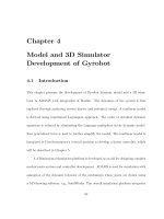
makers (Chua and Leong, 1997). The typical process chain of a general RP
technique is presented in Figure 2.7. A computer-generated 3D model based
on CAD design or MRI or CT scan data in .stl format is imported into a RP’s
system software that allows the model to be “sliced” into thin horizontal layers,
with the tool path specified for each layer. The “sliced” data is used to instruct
the RP machine to build a physical model layer by layer, based on the actual
shape of the computer model (Zein et al, 2002).
32
Chapter Two: Literature Review
RP
process
download
data
create
tool paths
import
export
Computer-Aid
ed Design
(CAD) model
.stl
(STereoLithography)
format
“sliced”
model
“sliced” model with
tool paths specified
RP
machine
Physical
model
slicing &
setting
parameters
RP’s
system
software
Figure 2.7: Flow diagram of a general rapid prototyping (RP) process.
The important features of RP technique in scaffold fabrication are as follows
(Leong et al, 2003a):
Customized Design: Direct utilization of CAD models as inputs allows
fabrication of scaffolds with geometric intricacy including branching and
enclosed cavities. RP techniques can be easily automated and integrated with
imaging techniques to produce scaffolds that are customised in size and shape
allowing tissue-engineered grafts to be tailored for specific applications or even
for individual patients.
Auto-controlled Fabrication: The use of automated computerized fabrication
results in high throughput production with minimal manpower requirements.
The high build resolution of RP technique promises precise matrix architecture
(pore size, shape and interconnectivity) yielding biomimetic structures, thereby
enhancing control over mechanical properties, biological effects and
degradation kinetics of the scaffolds.
33
Chapter Two: Literature Review
Anisotropic Microstructures: The use of CAD in RP technique holds control
over localized pore morphologies and porosities within the same scaffold
volume to suit the requirements of different cell types. This is achieved by
incorporating different controllable macroscopic and microscopic design
features in different regions of the same scaffold. This anisotropic scaffold
architecture gives special benefits where multiple cell types are needed to be
arranged in hierarchical structures (Park et al, 1998; Hutmacher et al, 2001b).
Processing Conditions: RP techniques employ a wide range of processing
conditions which allow building objects from multiple materials and even allow
varying materials in a controlled fashion at any location in the same scaffold.
The aqueous-based RP technique (Lam et al, 2002) a recent milestone in
scaffold fabrication, is operated at room temperature and offers opportunities
for inclusion of bioactive components, such as growth factors, cells and drugs.
Currently, a number of RP techniques have been exploited for tissue
engineering scaffold fabrication. The following sections describe the RP
techniques classifying on the basis of their processing technologies (Sachlos
and Czernuszka, 2003; Leong et al, 2003a; Hutmacher et al, 2004).
2.4.3.1 Systems Based on Laser Technology
Stereolithography Apparatus (SLA): Stereolithography (SLA) was first
commercialized in 1988 by 3D Systems Inc. (
www.3dsystems.com) and often
considered as the pioneer on the scene in RP techniques. This technique is
based on selective polymerisation of a liquid photopolymerisable monomer by
34