Advance servo control for hard disk drive in mobile application
Bạn đang xem bản rút gọn của tài liệu. Xem và tải ngay bản đầy đủ của tài liệu tại đây (2.87 MB, 129 trang )
Founded 1905
ADVANCED SERVO CONTROL FOR
HARD DISK DRIVES IN MOBILE
APPLICATIONS
BY
JINGLIANG ZHANG
(BEng, MEng)
A THESIS SUBMITTED
FOR THE DEGREE OF DOCTOR OF PH ILOSOPHY
DEPARTMENT OF ELECTRICAL & COMPUTER ENGINEERING
NATIONAL UNIVERSITY OF SINGAPORE
2011
I dedicate this dissertation to my lovely children: Jerry, Jenny and Jessie.
Acknowledgements
I would especially like to thank Professor Shuzhi Sam Ge, my supervisor, for his
many suggestions, constant support and guidance throughout this research. I would
also like to express my gratitude to Professor Frank Lewis for his kind help.
I express my sincere g ratitude to the Data Stor age Institute of Singapore f or its
support o f my part-time Ph.D. program.
Of course, I a m gr ateful to my family for their patience and love. Without them
this work would never have come into existence literally.
Finally, I wish to thank the following colleagues: Linlin Thi (for her patience
and hardworking in developing hardware and firmware for the experiment setup
together with me), Dr . Chunling Du and Dr. Fan Hong (for the endless chatter
about control theory and controller design), Dr. Qingwei Jia (for his friendship
and kind support).
Jingliang Zhang
December 27, 2010
i
Contents
Contents
Acknowledgements i
List of Figures vi
List of Tables x
Abstract 1
1 Introduction 2
1.1 Background of HDD and Magnetic Recording . . . . . . . . . . . . 2
1.2 Servo Control Issues in HDD . . . . . . . . . . . . . . . . . . . . . . 4
1.3 Outline of Chapters . . . . . . . . . . . . . . . . . . . . . . . . . . . 8
2 HDD Servo Mechanism and Modeling 10
2.1 The Servo Loop in HDD . . . . . . . . . . . . . . . . . . . . . . . . 11
2.2 Mechanical Structural Resonances . . . . . . . . . . . . . . . . . . 13
2.2.1 Spindle Motor . . . . . . . . . . . . . . . . . . . . . . . . . . 13
2.2.2 Disks Platter . . . . . . . . . . . . . . . . . . . . . . . . . . 15
ii
Contents
2.2.3 Suspension and Arm . . . . . . . . . . . . . . . . . . . . . . 16
2.3 Modeling of Servo System . . . . . . . . . . . . . . . . . . . . . . . 17
2.3.1 Modeling of VCM Actuator . . . . . . . . . . . . . . . . . . 17
2.3.2 Modeling of Micro-actuator . . . . . . . . . . . . . . . . . . 18
2.3.3 Modeling of Disturbances . . . . . . . . . . . . . . . . . . . 22
3 Design Pseudo-sine Current P rofile for Smooth Seeking 28
3.1 Problem Formulation for Track-seeking . . . . . . . . . . . . . . . . 30
3.1.1 Minimum Jerk Seeking . . . . . . . . . . . . . . . . . . . . . 30
3.2 2DOF with Model Referenced Position and Current Feedforward
Control . . . . . . . . . . . . . . . . . . . . . . . . . . . . . . . . . 31
3.3 The Strategy t o Design Pseudo-sine Current Profile . . . . . . . . . 33
3.3.1 Pseudo-sine Current Profile Generatio n . . . . . . . . . . . . 35
3.3.2 Minimizing Residual Vibrations . . . . . . . . . . . . . . . . 37
3.4 Simulation and Comparison with PTOS . . . . . . . . . . . . . . . 38
3.5 Conclusions . . . . . . . . . . . . . . . . . . . . . . . . . . . . . . . 43
4 IES Settling Controller for Dual-stage Servo System 44
4.1 Settling Problem in Dual-stage Servo Systems . . . . . . . . . . . . 45
4.2 IES for Dual-Stage Systems . . . . . . . . . . . . . . . . . . . . . . 47
4.2.1 IES for Initial Position . . . . . . . . . . . . . . . . . . . . . 48
4.2.2 IES for Initial Velocity . . . . . . . . . . . . . . . . . . . . . 49
iii
Contents
4.3 More Considerations in Designing F (z) . . . . . . . . . . . . . . . . 50
4.4 Design Example . . . . . . . . . . . . . . . . . . . . . . . . . . . . . 51
4.5 Implementation Method . . . . . . . . . . . . . . . . . . . . . . . . 57
4.6 Switching Conditions . . . . . . . . . . . . . . . . . . . . . . . . . . 58
4.7 Exp erimental Setup and Results . . . . . . . . . . . . . . . . . . . . 59
4.8 Conclusions . . . . . . . . . . . . . . . . . . . . . . . . . . . . . . . 60
5 Design Feedback Controller Using Advanced Loop Shaping 63
5.1 Control Design Using Generalized KYP Lemma . . . . . . . . . . . 65
5.1.1 Problem Description . . . . . . . . . . . . . . . . . . . . . . 65
5.1.2 Generalized KYP Lemma . . . . . . . . . . . . . . . . . . . 65
5.1.3 YOULA Parametrization . . . . . . . . . . . . . . . . . . . . 67
5.1.4 Design Procedures Using K YP Lemma . . . . . . . . . . . . 69
5.2 H
2
Optimal Control . . . . . . . . . . . . . . . . . . . . . . . . . . 70
5.2.1 H
2
Norm . . . . . . . . . . . . . . . . . . . . . . . . . . . . 71
5.2.2 Continuous-time H
2
Optimal Control . . . . . . . . . . . . . 73
5.2.3 Discrete-time H
2
Optimal Control . . . . . . . . . . . . . . . 75
5.3 Combine H
2
and KYP Lemma . . . . . . . . . . . . . . . . . . . . . 78
5.3.1 Problem Formulation . . . . . . . . . . . . . . . . . . . . . . 78
5.3.2 Design Controller for Specific Disturbance Rejection and Over-
all Error Minimization . . . . . . . . . . . . . . . . . . . . . 79
iv
Contents
5.3.3 Q Parametrization to Meet Specifications for Disturbance
Rejection . . . . . . . . . . . . . . . . . . . . . . . . . . . . 80
5.3.4 Q Parametrization to Minimize H
2
Performance . . . . . . . 82
5.3.5 Design Procedure . . . . . . . . . . . . . . . . . . . . . . . . 84
5.4 Exp erimental Setup and Results . . . . . . . . . . . . . . . . . . . . 85
5.4.1 Servo Writing Technolo gies . . . . . . . . . . . . . . . . . . . 85
5.4.2 STW Experimental Platform with Hybrid Dual-stage Servo . 86
5.4.3 System Functions of STW Platform . . . . . . . . . . . . . . 87
5.4.4 Servo Mechanism of STW Platform . . . . . . . . . . . . . . 88
5.4.5 Measurement and Modeling of Vibrations a nd Noises . . . . 90
5.4.6 Exp erimental Verification of the Controller Performance for
PZT Loop . . . . . . . . . . . . . . . . . . . . . . . . . . . . 94
6 Conclusions and Future Work 102
6.1 Summary of Results . . . . . . . . . . . . . . . . . . . . . . . . . . 102
6.2 Future Work . . . . . . . . . . . . . . . . . . . . . . . . . . . . . . . 104
Author’s Publications 105
Bibliography 107
v
List of Figures
List of Figures
1.1 Data storage density for disk drives versus time [1]. . . . . . . . . . 3
2.1 The mechanism inside a conventional HDD. . . . . . . . . . . . . . 10
2.2 A typical servo loo p in HDD. . . . . . . . . . . . . . . . . . . . . . 12
2.3 The bode plot of a typical sensitivity function. . . . . . . . . . . . . 13
2.4 The structure of ball bearing and fluid dynamic bearing. . . . . . . 14
2.5 The spindle resonant modes: pitch and radial. . . . . . . . . . . . . 15
2.6 The typical eigenmodes of disk. . . . . . . . . . . . . . . . . . . . . 15
2.7 The eigenmodes of suspension. . . . . . . . . . . . . . . . . . . . . . 16
2.8 The typical arm mode shapes: (a) lateral QR mode and (b) lateral
bending mode. . . . . . . . . . . . . . . . . . . . . . . . . . . . . . . 16
2.9 The block diagram of VCM model. . . . . . . . . . . . . . . . . . . 1 7
2.10 Bode plots of frequency response fo r VCM. (solid line: measured;
dotted: identified; dash-dotted: double integrator) . . . . . . . . . . 18
2.11 The t echnology evolution for micro-actuator. . . . . . . . . . . . . . 19
2.12 The dual-stage actuato r inside Seagate Cheetah 10K7 HDD. . . . . 20
vi
List of Figures
2.13 A PZT actuated suspension. . . . . . . . . . . . . . . . . . . . . . . 20
2.14 Equivalent spring mass system of PZT microactuator. . . . . . . . . 21
2.15 A typical frequency response of PZT microactuator. . . . . . . . . . 22
2.16 Block diagram of closed-loop with disturbances . . . . . . . . . . . 24
2.17 The NR RO spectrum measured in a commercial HDD. . . . . . . . 25
2.18 The bode plot of sensitivity function for a commercial HDD. . . . . 25
2.19 Control system with augmented disturbance and noise models. . . . 27
3.1 The current profile for conventional seeking controller. . . . . . . . . 29
3.2 The optimal current profile for minimum jerk. . . . . . . . . . . . . 32
3.3 Block diagram of the model referenced feedforwa rd control. . . . . . 32
3.4 Pseudo sinusoidal current profile. . . . . . . . . . . . . . . . . . . . 34
3.5 The process to generate current profile. . . . . . . . . . . . . . . . . 36
3.6 The block diagram of PTOS. . . . . . . . . . . . . . . . . . . . . . . 39
3.7 The block diagram of 2 DOF with MRF. . . . . . . . . . . . . . . . 39
3.8 Position output for one track seeking. . . . . . . . . . . . . . . . . . 4 0
3.9 Velocity and current profile for one track seeking. . . . . . . . . . . 40
3.10 Position output for 50 tracks seeking. . . . . . . . . . . . . . . . . . 41
3.11 Velocity and current profile for 50 tracks seeking. . . . . . . . . . . 42
3.12 Input current while seeking with different T
1
. . . . . . . . . . . . . . 42
3.13 Input current while seeking with different T
h
. . . . . . . . . . . . . 43
vii
List of Figures
4.1 Parallel-type dual-stage servo system. . . . . . . . . . . . . . . . . . 45
4.2 Equivalent closed-loop control system with IES for initial position
and velocity. . . . . . . . . . . . . . . . . . . . . . . . . . . . . . . . 47
4.3 Frequency response of VCM actuator. . . . . . . . . . . . . . . . . . 52
4.4 Frequency response of PZT micro-actuat or. . . . . . . . . . . . . . . 52
4.5 Step response of the dual-stage servo system. . . . . . . . . . . . . . 53
4.6 Poles/zeros map of the closed-loop system. . . . . . . . . . . . . . . 54
4.7 Settling transient due to initial position y
0
= 1 track (A: no compen-
sation; B: with compensation and without considering acoustic and
slow modes; C: with comp ensation considering acoustic and slow
modes). . . . . . . . . . . . . . . . . . . . . . . . . . . . . . . . . . 55
4.8 VCM controller output with initial position compensation (B: acous-
tic oscillation observed; C: no acoustic problem). . . . . . . . . . . . 56
4.9 Settling transient due to init ial velocity. . . . . . . . . . . . . . . . . 57
4.10 PZT output under different initial conditions with IES. . . . . . . . 59
4.11 Experiment setup for dual-stage servo. . . . . . . . . . . . . . . . . 6 0
4.12 Seeking profile with FIR seeking controller. . . . . . . . . . . . . . . 61
4.13 Experimental results with IES (A: no compensation; B: with com-
pensation). . . . . . . . . . . . . . . . . . . . . . . . . . . . . . . . . 61
5.1 Equivalent system for KYP analysis. . . . . . . . . . . . . . . . . . 66
5.2 Configuration of standard optimal control. . . . . . . . . . . . . . . 74
5.3 H
2
control scheme with Q parametrization for controller design. . . 78
viii
List of Figures
5.4 Dual stage STW experimental platform. . . . . . . . . . . . . . . . 86
5.5 Functional block diagram of the HSSTW platform. . . . . . . . . . 87
5.6 Hybrid dual-stage servo system. . . . . . . . . . . . . . . . . . . . . 88
5.7 Equivalent PZT servo loop. . . . . . . . . . . . . . . . . . . . . . . 90
5.8 Spectrum of PES NRRO without the second loop. . . . . . . . . . . 91
5.9 The format of servo bursts and typical servo pattern r eadback signal. 91
5.10 Spectrum of PES demodulation noise. . . . . . . . . . . . . . . . . . 92
5.11 Frequency response for piezo chip. . . . . . . . . . . . . . . . . . . . 93
5.12 Sensitivity function simulated. (solid: KYP; dashed: PLPF). . . . . 97
5.13 Open loop frequency response. (solid: KYP; dashed: PLPF). . . . . 97
5.14 Spectra of PES NRRO with the secondary loop (solid: KYP; dashed:
PLPF). . . . . . . . . . . . . . . . . . . . . . . . . . . . . . . . . . 98
5.15 Frequency response of o pen-loop transfer functions. (solid: KYP+H
2
;
dashed: KYP). . . . . . . . . . . . . . . . . . . . . . . . . . . . . . 100
5.16 Simulations of sensitivity function. (solid: KYP+H
2
; dashed: KYP). 100
5.17 Sensitivity functions measured. (solid: KYP+H
2
; dashed: KYP). . 101
5.18 Spectra of PES NRRO with the secondary loop (solid: KYP+H
2
;
dashed: KYP). . . . . . . . . . . . . . . . . . . . . . . . . . . . . . 101
ix
List of Tables
List of Tables
3.1 Parameters for resonant modes . . . . . . . . . . . . . . . . . . . . 38
4.1 Characteristic of poles/zeros in tracking. . . . . . . . . . . . . . . . 54
4.2 PZT output at different initial conditions. . . . . . . . . . . . . . . 58
5.1 Tracking accuracy for different servo bandwidth. . . . . . . . . . . . 94
5.2 Performance with different controllers for PZ T loop. . . . . . . . . . 99
6.1 Performance of servo controllers using different design method. . . . 103
x
List of Tables
Abstract
This thesis provided solutions to the following three major problems that HDD
servo system encountered in the application of mobile consumer devices: acoustic
noise and residual vibrations problem induced from track seeking, smooth settling
problem during mode-switching, and disturbances rejection problem for high pre-
cision tracking accuracy. To reduce the seeking acoustic noise, a pseudo sinusoidal
current profile for any seeking span was designed for the 2DOF seeking controller
with consideration of driver saturation, and a design method was derived to chose
a set of proper values of the par ameters for the current profile such that the resid-
ual vibratio ns due to the dominant structural resonances can be minimized. To
achieve the smooth a nd fast settling for dual stage servo systems which are the
servo mechanism for next generation high density HDD , a feedforward compen-
sator was proposed ba sed on zero phase error tracking control. This feedforward
compensator can be used to cancel the undesired transitions due to the non-zero
initial states of VCM actuators, and hence achieve smooth and fast settling while
switching from seeking mode to following mode. To achieve better tracking accu-
racy, an approach combining the KYP lemma together with H
2
optimal method
was proposed. This method can be used to shape the sensitivity function of the
HDD servo loop to attenuate a few dominant disturbances at a specific frequency
range and achieve the minimization o f overall track misregistration of the servo
system.
1
Chapter 1
Introduction
1.1 Background of HDD and Magnetic Recording
Magnetic hard disk dr ives (HDD) are non-volatile random access storage devices
which store digitally encoded data on rapidly rotating platters using a mot or-
driven spindle in a pro t ective enclosure. In 1957, IBM first introduced HDD as
a data storage device for IBM accounting computer. With the rapid progresses
of magnetic recording related technologies in servo, mechanics, signal processing,
magnetic recording physics, media mat eria ls, recoding head processing, and tribol-
ogy, the data storage areal density of HDD has been increasing dramatically at
the average compound growth rate of around 60% per year through the 1990’s, as
shown in Figure 1.1. Today, the areal density has achieved around 400 Gbits/in
2
,
and the corresponding track density is around 300,000 tra cks per inch ( TPI), with a
data transfer rate of more than 125 MBytes/second. Therefore, the market applica-
tions of HDDs have expanded from general purpose computers to most computing
applications including a lot of consumer applications, like digital video recorders,
digital audio players, personal digital assistants, digita l cameras, and video game
consoles, etc.
2
1.1 Background of HDD and Magnetic Recording
Figure 1.1: Data storage density for disk drives versus time [1].
Areal density, also sometimes called bit density, refers to the amount of data that
can be stored in a given amount of hard disk platter. Areal density is a measure
of the number of bits that can be stored in a unit of area. It is usually expressed
in bits per square inch (BPSI).
Being a two-dimensional measure, areal density is computed as the product of two
other one-dimensional density measures:
1. Track density: This is a measure of how tightly the concentric tracks on the
disk are packed. It is specified by tracks per inch (TPI), which tells how
many tracks can be placed down in one inch of ra dius on the platters.
2. Linear or recording density: This is a measure of how tightly the bits are
packed within a length of track. It is specified by bits per inch (BPI), which
tells how many bits can be written along one inch of tra ck.
3
1.2 Servo Control Issues in HDD
There a r e two ways to increase areal density: increase the linear density by packing
the bits on each t r ack closer together so that each tr ack holds more dat a; o r increase
the track density so that each platter holds more tracks. Typically new generation
drives improve both measures. It’s important to realize that increasing areal density
leads to drives that are not just bigger, but also faster. The reason is that the areal
density of the disk impacts both o f the key hard disk performance factors: the
track to track positioning speed and data transfer rate.
Increasing the ar eal density of disks is a difficult task that requires many technolog-
ical advances and changes to various components of the hard disk [2]. As the data
is packed closer and closer together, problems result with interference between bits.
This is often dealt with by r educing the strength of the magnetic signals stored
on the disk, but then this creates other problems such as ensuring that the signals
are stable on the disk and that the read/write (R/W) heads are sensitive and close
enough to the surfa ce to pick them up. Changes to the media layer on the platters,
actuators, control electronics and other components are made to continually im-
prove areal density. Every few years a R/W head technology breakthrough enables
a significant jump in density, which is why hard disks have been doubling in size
so frequently, as shown in Figure 1.1 .
1.2 Servo Control Issues in HDD
The HDD servo systems play a vital role in the demand of increasingly high t r ack
density and high performance HDDs. In HDDs, the servo system provides two
major functions: track seeking and track following. The track seeking servo moves
R/W head from one track to another in minimal time, which is seeking time. The
less the seeking time is, the faster the data can transfer. The track following servo
maintains the R/W head position over the center of a target track. The measured
deviation of R/W head from the center of t he track is called position error signal
4
1.2 Servo Control Issues in HDD
(PES). It is the performance of track following servo that limits the achievable
track density. The tracking accuracy of HDD servo is often measured by a 3σ
number of PES, assuming a Gaussian distribution. This performance measure is
also called as t rack misregistration (TMR). Typical TMR is 12% of the track width,
which matches with the off-track-reading-capability (OTRC) of the coding channel.
OTRC is a measure of the R/W system’s ability to read previously-written data
as a function of servo tracking-error, and proximity o f an adjacent data-track. If
TMR is larger than 12%, the data reading channel will have unrecoverable error.
In general, the HDDs have top performance if TMR is less than 5% of track 99.7%
of the time.
The track-following control in HD Ds is an inherently difficult problem, as the plant
is marginally stable and it becomes unstable in the presence of delays due to sam-
pling and computation. Besides this, the HDD servo system is non-collocated, as
sensors are placed at the read head while control is applied at the voice-coil-motor
(VCM) [3] [4]. Furthermore, the servo system in HDD is non-minimum phase
system, which imposes limits on tracking performance [5]. The servo robustness
and tracking accuracy are limited by the following factors: (1) resonance and gain
variations between heads, at different radius, ages, and temperatures; (2) excessive
three-dimensional vibratio ns; (3) mechanical constraints (e.g. form factor) limit
the dynamic pr operties of the plant, which in turn place limitations on the con-
troller performance; (4) uncertainties, and no nlinearities, such as friction due to
near contact recording and pivot, and backlash/hysteresis of micro-actuator/milli-
actuator.
Traditionally, HDD servos are designed using linear control theory. Current disk
drive utilizes typical linear feedback digital control systems based on error signal,
PES. The PES is demodulat ed f r om the position information that is encoded onto
the disks during the manufacturing process. PID controllers were used initially,
and t hey a r e subsequently augmented with notch filters to suppress the mechanical
5
1.2 Servo Control Issues in HDD
resonant modes, thereby increasing the bandwidth. The performances of these
methods are limited by the effects of Bode Integral Theorem [6]. As a consequence
of this theory, servo loop will amplify vibrations at other frequencies [7], if the
servo sensitivity transfer function is designed to reject more vibrations in some
frequencies. This is also known as waterbed effect.
Another formidable challenge for track-following controller is to achieve precise
tracking accuracy so as to satisfy the requirement for ultra-high track density higher
than 500k TPI, despite the presence of uncertainties in the dynamic model. PES
demodulation noise in HDD is scaled with signal to noise ratio (SNR) of head and
media, and used to be the majo r TMR sources. However, for high density HDD
in mobile applications, disturbances ar e no longer limited to PES noise, but also
disk motion, air flow, and external vibration, etc. Although external sensors, such
as accelerometers, can be used in the suppression of external vibrations in order
to maintain the tracking accuracy [8] [9] [10] [11], the relationship between XY
acceleration and PES may be highly nonlinear, which results in furt her difficulties
in the design of feed for ward controllers. In addition, some nonlinearities currently
being neglected or simplified in cont rol system design must be taken into account
for a system with such a high accuracy requirement. The nonlinearities preventing
the system accuracy of a hard disk drive from further improvement include ribbon
flexibility and nonlinear friction o f the actuato r pivot of a HDD [12] [13] [14].
Furthermore, inconsistencies of system parameters between units are prevalent as
HDDs are ma ss-produced products. These parameters vary with age and thermal
effects, although the time scales are usually sufficiently large such that they can be
considered to be slowly-varying or even time-invariant.
Therefore, the track-following servo controller are designed with two kinds of funda-
mental trade off , performance trade-off due to bode integration, and perfo rmance
trade-off with system robustness due to uncertainties of plant dynamic and dis-
turbances. The performance versus robustness trade-off is an importa nt aspect
6
1.2 Servo Control Issues in HDD
of the development of H
∞
control theory [15] [16]. Many papers are published
on t he loop-shaping design methods to look for the reasonable trade-off between
robustness and performance [17] [18] [19].
A few researchers have investigated t he feasibility of applying adaptive or learning
algorithms like neural network and f uzzy control. In [20] [21] [22] [23], an adaptive
neural network controller is designed to compensate for the pivot nonlinearity. In
[24], a model-based ada pt ive controller is added to a linear time invariant (LTI) sta-
bilizing controller to minimize the t r acking error of the read/write head. In [25], an
adaptive robust controller was developed, which is applicable to both track-seeking
and track-following. In [26] [27 ] [28] [29], an adaptive notch filter was designed to
compensate for the resonant modes with uncertain frequencies. However, most of
the adaptive algor ithms ar e not feasible in HDD servo due to either robustness,
or degraded performance with existence of noise and disturbances, or the slow
convergence of adaptation.
In a traditional HDD servo system, nonlinear controllers such as proximate time-
optimal servo (PTOS) [30] [31] [32] are widely used for t rack-seeking. Other efforts
include designing a unified control structure for both track-seeking and following,
such as two-degree-of f r eedom (2DOF) servo mechanism with adaptive robust con-
trol and zero phase erro r tracking techniques [33] [34] [35]. Most of these works
focus on reducing seeking and settling time. But for t he HDDs application in
consumer electronics where the quietness is essential, such as home entertainment
system, car navigation and digital video recorder, HDD acoustic no ise is one of the
key perfo r ma nce indices most concerned. Another challenge for the seeking/settling
controller is the residual vibrations induced in the transition switching from seek-
ing to track-following [36] [37] [38]. The residual vibrations are not only one o f the
significant TMR sources, but may also induce acoustic noise.
7
1.3 Outline of Chapters
1.3 Ou tline of Chapters
The contributions presented in this dissertation include the following: (1) Pro-
posed an advanced systematic loo p shaping method using Kalman-Yakubovic-
Popov (KYP) Lemma to optimize the track-following controller with considera-
tions of the spectrum models of input disturbances, output disturbances and sens-
ing noise. The method was experimentally validated in our servo writing platform;
(2) Proposed a method to design an o ptima l seek current profile for the seeking
controller to reduce acoustic noise and residual vibrations; (3) Proposed and ex-
perimentally validated a novel settling controller for dual-stage servo system to
achieve fast and smoothly settling on target track.
The dissertation is organized as follows. In Chapter 2, the mechanical components
used in current HDDs are described. It details the possible sources of TMR during
normal operation and when the HD D is subjected to external shock and vibrations.
It also provides the modeling of the typical VCM actuator, piezoelectric (PZT)
micro-actuator, disturbances and noises.
In Chapter 3, the seeking process in HDDs is detailed. We propose a direct ap-
proach to design the pseudo-sinusoidal seek current profile, which is able to reduce
both the acoustic no ise a nd residual vibrations. With consideration of both cur-
rent saturation limit and maximum seeking velocity limit, the saturatio n period,
frequency of sinusoidal wave, and coasting time can be optimally designed for ar-
bitrary seeking span to reduce residual vibrations.
In Chapter 4, the dual-stage servo system in HDD is first introduced. We formulate
the problem due to the initial values of states in the transition from track-seeking
to track-following. After a brief discussion of the conventional initial value compen-
sation (IVC) method, we describe the new proposed method initial error shaping
(IES) basing on the zero-phase error tracking (ZPET), followed by the experimental
results.
8
1.3 Outline of Chapters
In Chapter 5, a general KYP-method is introduced to shape the sensitivity function
and suppress the disturbances at certain frequencies. With the spectrum model of
disturbances and noises, an H
2
optimal method is introduced to design an optimal
feedback control to achieve overall an optimal tracking p erf ormance. A systematic
procedure is then presented to design an optimal track-following controller com-
bining KYP-lemma with H
2
optimal control. We introduce the servo loops in the
servo writing experimental plat form and present experimental results to verify the
performances of controller designed with different approaches.
In the final chapter, Chapter 6, the major results and achievements of this research
are summarized. Further, a recommendation for future work is also outlined.
9
Chapter 2
HDD Servo Mechanism and
Modeling
VCM Arm
Suspension
Disk Stack
Recording Head
Pivot Bearing
Flexi-Cable
Base Casting
Spindle
u-actuator
Tracks
Figure 2.1: The mechanism inside a conventional HDD.
Figure 2.1 shows an overview of the mechanism inside a HD D. The major compo-
nents in a modern HDD include: 1) device enclosure, which usually consists o f a
base plate and a cover to provide supports to the spindle, actuator, a nd electronics
card; 2) disk stack assembly, where several disks are stacked on the spindle motor
shaft and rotate at up to 15,000 rotations per minute (RPM) in high end 3.5-inch
drives and 5,400 - 7,200 RPM in 2.5-inch drives. On t he surface of a disk, sev-
eral hundred tho usand da t a tracks are magnetically recorded, and the latest track
10
2.1 The Servo Loop in HDD
pitch is about 8 0 nm; 3) head stack assembly which contains of a voice coil mot or
(VCM), actuator arm, suspension and g imbal assembly. A slider is supported by
a suspension and a carriage, and is suspended at less than ten nanometers above
the disk surface. The VCM actuates the carriage and moves the slider on a de-
sired track. To increase the servo bandwidth to improve positioning accuracy for
higher track density drives, dual-stage servo using a suspension-driven PZT micro-
actuator has been commercially applied to HDD; 4) electronics circuit bo ard which
involves drivers for spindle motor and VCM, read/write (R/W) electronics, servo
channel demodulator, a micro processor/digital signal processor (DSP) for servo
control and the interface to host computer. The position signals are recorded mag-
netically on each disk using a servo track writer (STW). The position signals are
recorded in a certain time interval on each track. Consequently, the PES between
the head and the reference track center can be detected directly by reading the
position signal.
2.1 The Servo Loop in HDD
The head-positioning servomechanism in HDD is a control system that moves the
R/W head from current track near to ano t her target track (tr ack-seeking), and
re-positions the R/W head over a desired track center with minimum statistical
deviation from the track center (track-following). A settling controller is used in
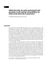
between the above seeking and f ollowing modes. Figure 2.2 shows the typical
functional block diagram where plants involve VCM and PZT a ctuators for the
dual-stage servo system in HDD. The plant dynamics (P (s) + ∆P (s)) include the
dynamic of arm, suspension, and driver, and y is the position of R/W head (it is
the sum of VCM and PZT o utput for dual-stage HDD). y
r
is the reference input
of the desired track center. pes
t
is the true PES signal which tells exactly how
well the R/W head follows the reference track center. n is measurement noise
11
2.1 The Servo Loop in HDD
Figure 2.2: A typical servo loop in HDD.
which includes the electronic noise of demodulation circuit, head noise, and media
noise. pes is the measured error for feedback control. d
i
is the input disturbance
which includes torque disturbances and external shock disturbances. d
o
is the
output disturbance which includes the disk vibrations,slider vibrations, suspension
vibrations, and spindle vibrations. T
s
is the sampling time, which is decided by
the sector number in one revolution and the rotation speed of spindle.
Figure 2.2 shows tha t t he HDD servo has four features:(a) typical error feedback
controller (b) sampled digital servo control (c) disturbance suppression control
including hig h servo bandwidth design, and (d) transient r espo nse control such as
mode-switching control (MSC).
For the single-stage servo in track-following mode, we have
pes
t
(k) = −P (z)S(z)d
i
(k) + S(z)d
o
(k) − S(z)P (z)C(z)n(k), (2.1.1)
from Figure 2.2. where P(z) is the transfer function of the discretized plant model
P (s), C(z) is the track-following controller, and the sensitivity function or error
rejection function is given by
S(z) =
1
1 + P (z)C(z)
. (2.1.2)
12
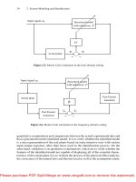
2.2 Mechanical Structural R esonances
which is shown as in Figure 2.3.
(2.1.1) tells t hat the servo tracking accuracy (3σ(pes
t
)) is limited by the disturbance
rejection capability of sensitivity function and the distribution of disturbances in
frequency domain. An improved mechanical design is expected to have less internal
structural vibrations and provides t he actuator with better dynamic performance.
On the other hand, a good closed-loop servo system is expected to be able to reject
more disturbances. This typically demands a high servo bandwidth, which requires
actuators to be of better dynamic performance. A low hump with amplification of
less than 6 dB in error t ransfer function will also be observed.
rejection
amplification
0 dB cross frequency
Figure 2.3: The bode plot of a typical sensitivity function.
2.2 Mechanical Structural Resonances
2.2.1 Spindle Motor
The structures of ball bearing and fluid dynamic bearing mo t ors a re shown in
Figure 2.4 [1]. Fluid dynamic bearing (FDB) motors provide improved acoustics
over traditional ball bearing spindle mot ors. The source of acoustic noise in the
HDD is the dynamic motion of the disk and spindle motor components. The
sound components are generated from the motor magnet, stator, bearings, and
13