Growth and transmission electron microscopy studies of nanomaterials 1 2
Bạn đang xem bản rút gọn của tài liệu. Xem và tải ngay bản đầy đủ của tài liệu tại đây (1.39 MB, 55 trang )
Chapter 1 Introduction
1
Chapter 1 Introduction
Nanotechnology is rapidly emerging as an important research field all over
the world because of its potential for revolutionizing every aspects of modern day
science. Technological bottlenecks in the roadmap for semiconductor technology are
creating increasingly more complex problems for scientists which call for a
paradigm shift in the fundamental concepts and architecture of electronic devices
and materials processing. It is inevitable that nanotechnology will play a central role
in this due to the new possibilities presented by dimensional materials, as well as the
increasingly demanding manipulation and processing techniques required for the
assembly and manufacture of these devices.
Dimensional nanomaterials present fundamentally different physical
concepts to conventional bulk materials because of their unique density-of-states as
well as vibrational and electronic confinements. Confinement effects are attributed
to the electronic and vibrational excitations with characteristic lengths comparable to
the diameter of the crystallites. As a result, substantial modifications of the density
of states and electronic structure should be expected. The challenge therefore is to
create nanomaterials with a monodispersion in their sizes, and then to study the
correlation in properties, size and structure. However, the synthesis of nanomaterials
with controlled dimensions, desired shapes, as well as oriented growth on a substrate,
Chapter 1 Introduction
2
is technically non-trivial. The growth of uniformly-sized dimensional nanomaterials
requires careful control of catalyst size and dispersion matrix to prevent aggregation.
Ordered orientation of the nanomaterials on a substrate, or selective growth of the
nanomaterials for making wire circuitry and devices, in a manner that is compatible
with large scale industrial synthesis and conventional microelectronic processing
methods, are technologically challenging problems. A number of novel strategies
have been developed to address these targets.
This thesis is motivated by the challenge of synthesizing semiconductor
nanomaterials that may have potential applications in electronic devices. Using
chemical vapor deposition, a range of semiconductor nanomaterials has been
successfully synthesized. These include BN nanocapsules, ZnS nanowires, SiC
nanocones and CuInS
2
thin films. The internal microstructure of these materials will
be mainly studied using TEM and other characterization tools. Other areas which
will be discussed in this thesis include the relationship between the size of
nanomaterials and the catalysts, the influence of growth conditions on the
morphology and structure of final products, the growth mechanism of these
nanomaterials, and the mechanism of morphology and phase transfer of these
nanomaterials.
In the following section, a brief introduction to the science and technology of
nanomaterials will be presented. Following which, several characterization
Chapter 1 Introduction
3
techniques will be discussed with particular emphasis on the application of TEM for
the characterization of nanomaterials. Finally a brief introduction to the following
chapters will be presented.
“In the great future we can arrange the atoms the way we want; the very
atoms, all the way down!”
Richard Feynman, 1959
1.1 Nanotechnology
Nanotechnology can be broadly defined as the application of science to
develop new materials and processes by manipulating molecules and atoms in the
length scales of 1-100 nanometers. In general, any technology related to features of
nanometer scale: thin films, fine particles, chemical synthesis, advanced
microlithography, and so forth can be classified as nanotechnology. It is an
interdisciplinary field which can impact the traditional disciplines of physics,
chemistry and biology at the fundamental molecular and atomic level. In terms of
engineering, devices are constructed at the molecular scale and function at this scale.
However, nanotechnology is not simply a miniaturization in size, but an entire
paradigm shift in physical concepts, system design and materials manufacturing.
This technology is expected to allow the construction of very compact and high
performance computing devices or molecular sensors. High hopes have been pinned
Chapter 1 Introduction
4
on nanotechnology to provide the impetus for breakthroughs needed in many areas
which has reached conventional technological limits.
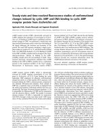
1.2 Nanomaterials
Table 1.1 Examples of dimensional nanomaterials
Dimension Existing type Examples
2-D
Quantum
wells
super-thin
films
(a) InAsP/InGaP multi-quantum wells (Campi R etc, J.
Crys. Growth) [2]; (b) wurtzite ZnS single-crystal
nanosheets (Yu SH etc, Adv. Mate.) [3]
1-D
nanowires
nanorods
nanotubes
nanocones
(a) Au nanotubes (Sun Y, Nano Lett.) [4]; (b) Well aligned
ZnO nanowires (Huang, M etc Science) [5]
0-D
(the sizes
of the
materials
are nm in
length )
Quantum dots
(a)InGaAs/GaAs quantum dots (Ozasa K etc,
Ultramicroscopy) [6]; (b) Ag nanocubes (Xia etc,
Science)[7]
(b
)
(a)
(a)
(b)
Chapter 1 Introduction
5
The enabling of nanotechnology requires the use of nanomaterials, which
refer to materials wherein at least one dimensional size is on nanometer scale (1-100
nm). According to the geometric dimensionality, nanomaterials can be categorized
into three groups: Two dimensional (2-D), one dimensional (1-D) and zero
dimensional (0-D) nanostructured materials. Table 1.1 lists current examples of
dimensional nanomaterials and their usage in technologies.
Nanomaterials have unique optical, electronic and catalytic properties, which
often depend strongly on their size and are very different from the corresponding
bulk materials. For example, the bandgap of CdS quantum dot can be tuned between
2.5 to 4 eV, while the irradiative rate for the lowest allowed optical excitations
ranges from several nanoseconds down to tens of picoseconds when its size
decreases to nanometer scale [1].
If the size of the crystal is small enough, quantum confinement due to
discrete electron charge or energy levels can be observed macroscopically. Quantum
confinement means that electrons are trapped in a small area, like particles in a box
model. The nanomaterials show continuous energies and momentum in free
directions, and confinement restricted in 1 (2D nanomaterials), 2 (1D nanomaterials)
and 3 (0D nanomaterials) directions. The energy separations of the confined states
and their numbers depend on the materials property, the length scale and potential
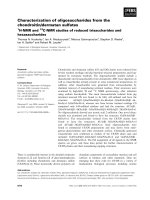
offsets. Figure 1.1 illustrates the simple relationship between density of states and
Chapter 1 Introduction
6
confinement dimensions. The accurate treatments of confinement require high-order
calculations to account for the band structures. However, most investigations of
quantum confinement now focus on its optical effects, which is similar to the
tunable optical excitations of CdS nanodots mentioned above.
Figure 1.1 Density of states characterized by the confinement dimension.
The interests in nanomaterials are sometimes motivated and sustained by the
availability of powerful electron microscope for studying these materials. It is only
when materials are observed under these microscopes that the possibilities of
generating nanosized particles in chemical reactions can be verified. The greatly
improved resolution and sensitivity of modern microscopes provides the opportunity
for the “discovery” of carbon nanotubes by Prof Ijima [8]. When Richard Feynman
Bulk
Energy
DOS
0D
2D
1D
Chapter 1 Introduction
7
gave his classic talk in 1959, the highest attainable resolution of transmission
electron microscopy (TEM) was only 1 nm. The resolution of current state-of-art
TEM has improved to 0.19 nm (the size of an average atom) when carbon nanotubes
were discovered in 1991. The invention of other new instruments also promotes
research on nanomaterials. In the early 1980’s, the scanning tunneling microscope
(STM) was invented at IBM-Zurich in Switzerland. This was the first instrument
that was able to “see” atoms in conductive and semiconductor materials. A few years
later, the Atomic Force Microscope (AFM) was invented, expanding the types of
materials that could be investigated to insulating materials. Currently, a large
number of techniques, such as Scanning Electron Microcopy (SEM), small-angle
X-ray Diffraction (SAXRD), scanning auger spectroscopy and Photoluminescence
(PL) have been applied to help scientists to obtain more detailed information about
nanomaterials.
1.3 The applications of TEM on the study of nanomaterials
Among all the characterization instruments, TEM is one of the most
powerful tools used routinely and has played the most important role in
characterizing nanostructures. Its ability for providing information on the internal
microstructure of nanomaterials at resolution down to atomic level surpasses that of
most other instruments. One example is the determination of composition of
Chapter 1 Introduction
8
quantum dots. The spatial resolution of XPS, STM and PL can not determine the
compositional variations within the dot but TEM allows the determination of several
levels of information: from the elemental mapping of the dot, to the study of the
epitaxial interface between the dot and substrate, to the determination of the
crystalline quality of the dot [9, 10].
TEM can be operated in various modes for the characterization of the
structural and electronic properties of materials (table 1.2) Due to a large number of
literatures and publications in this area, focus will be placed on the TEM techniques
that are used in this thesis and some recent novel applications used in
nanotechnology.
Table 1.2 TEM techniques used in nanotechnology
Techniques Information provided Chapter
Imaging Morphology, shape and internal structure 1.3.1
Diffraction pattern Internal crystal structure 1.3.1
EDX Chemical and electronic structure 1.3.2
EELS
Chemical and electronic structure; elemental
distribution and phase mapping
1.3.2
Holographic mapping electric and magnetic fields 1.3.3
Observing dynamic phase transformation process
and surface reactions
1.3.4.1
Observing the growth process of nanomaterials 1.3.4.2
in-situ TEM
Nanomeasurement of physical properties 1.3.4.3
Chapter 1 Introduction
9
1.3.1 Crystal structure of nanomaterials
The most important application of TEM is used for the characterization of
the internal nanostructure of materials, a good example is the study of the structure
of carbon nanotube. In High Resolution TEM images, the parallel fringes (0002)
shown in figure 1.2 are the profile view of tube walls that is tangent to the electron
beam. The uniform spacing between the parallel fringes that corresponds to the tube
walls is 0.34 nm, which indicates the structures are seamless and have a tubular
structure [8].
Figure 1.2 HRTEM images of multi-walled carbon nanotubes. (Iijima S. Nature 354, 56,
1991)
Combined with diffraction patterns, TEM can provide direct imaging of the
surface structures, chirality of nanotubes, and the distribution of atoms in one sheet
layer. Figure 1.3 shows a HRTEM image of a WS
2
coated multi-walled carbon
Chapter 1 Introduction
10
nanotubes [11]. The WS
2
coating, verified by EDX, shows a fringe which is darker
than the layers of carbon surrounding the carbon nanotube.
Figure 1.3 HRTEM image of a WS
2
partly coated MWCN (arrows indicate amorphous
WO
3
). (Whitby RLD etc, Chem. Phys. Lett. 2002, 359, 121)
Figure 1.4a shows the diffraction pattern derived from the image in figure
1.3. The (0002) carbon plane is observed as a streak extending across the center of
the image (arrow A, Figure 1.4b) and some faint (
0110 ) carbon spots (black dashed
line, Figure 1.4b) are visible outside the ring of WS
2
spots. The horizontal spots
spacing (arrow B) is ca. 0.21 nm, corresponding to an armchair edge of (
0110
).
Additionally, two sets of diffraction spots arising from front and rear regions appear
in hexagonal arrays, which match the diffraction pattern of the hexagonal WS
2
structure. The two hexagonal arrays are rotated away from each other by ca. 17° and
are inclined at ca. 8.5° to the CNT axis. In other words, the WS
2
coating is an 8.5°
helical tube. The hexagonal pattern, clearly seen between two walls, corresponds to
the extension of the WS
2
single sheet coating on the back of the CNT, as shown in
Chapter 1 Introduction
11
Figure 1.4c. Individual spots correspond to W atoms. The W–W distance is 3.1 Å
which is consistent with the WS
2
structure. HRTEM simulations of WS
2
tube were
performed to clarify the complex hexagonal structure seen in the WS
2
fully-coated
area. The combination of hexagonal patterns produced from front and rear halves are
in good agreement with experimental results (Fig. 1.4a right side).
Figure 1.4 left: (a) Diffractogram obtained from a Fourier transform of the WS2-coated
MWCN; (b) An indexed diffractogram, it is not possible to distinguish the front and back
layers without further tilting experiments. Right: (a) Enhanced TEM image of WS
2
-coated
area; (b) A simulated (90, −14) WS
2
tube; (c) Simulated HRTEM image for the front half of
a (90, −14) WS
2
tube (E=400 kV, Cs=0.90 mm, def=−384.7 Å, div=0.50 mrad, Drms=100.0
Å). (d) Simulated HRTEM image for the rear-half of a (90, −14) WS
2
tube. (e) Simulated
HRTEM image for the whole (90, −14) WS
2
tube. (Whitby RLD etc, Chem. Phys. Lett.
2002, 359, 121)
Chapter 1 Introduction
12
In addition to obtain the structure of nanotubes, the structure of single
crystalline nanowires can also be explained by TEM. The crystal plane on the
surface and the growth direction of one-dimensional nanowires play important roles
in determining their structural stability and influence the electronic and optical
properties. By changing the experimental parameters and synthesis methods, it is
reasonable to achieve precise orientation control during nanowire growth for
specific applications of nanowires.
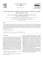
Figure 1.5 (a) HRTEM image of a ZnO nanobelt and its Fourier transform; (b) Optical
diagram for Shadow image technique for determining the growth direction of a
nanowire/nanobelt; (c) Optical diagram for imaging a nanowire under parallel beam
illumination and recording the diffraction information from the nanowire by converging the
electron beam and under-focusing the objective lens. (Wang, Z.L. J. Phys. Chem. B 2000,
104, 1153.)
Therefore, it is necessary to determine the growth orientation of nanowires
by TEM. It is often important to determine the rotation between the recorded
diffraction pattern and the image due to a change in optical mode. The most direct
method for determining the nanowire growth direction is from a HRTEM image of
(a)
(b)
(c)
Chapter 1 Introduction
13
the nanobelt and its Fourier transform. [12] Figure 1.5a is a HRTEM image of the
ZnO nanobelt. The Fourier transform of the image gives the growth direction of the
nanobelt clearly as [
0101
]. Shadow imaging is another technique for determining
the nanowire growth direction. An image and a convergent beam diffraction pattern
can be captured simultaneously in diffraction mode (Figure 1.5b), simply by
changing the beam focus so that the beam cross over is either under or over the
object. In this case, the index of the diffraction spot
g
that is parallel to the nanobelt
is the growth direction, provided the incident beam is perpendicular to the nanowire.
The third technique for directly determining the nanobelt growth direction is
presented in Figure 1.5c. The first step is to form a bright field TEM image using a
parallel illumination beam and record the image at in-focus condition (left, Figure
1.5c). The second step is to converge the beam onto the specimen, then to
underfocus the objective lens so much that diffraction spots appear in image mode
(right, Figure 1.5c). The next step is to record this image. The index of the
diffraction spot parallel to the nanobelt is the growth direction.
Hence, TEM can be used not just as a routine characterization technique, but
as a means to improve the quality of nanomaterials based on the observation results
in mass production.
Chapter 1 Introduction
14
1.3.2 Chemical and electronic structure of nanomaterials
Besides information on the crystal structure of nanomaterials, the chemical
and electronic structure information can also be obtained at high spatial resolution.
Under the impact of the incident electrons, the electrons at the ground state atoms
may be excited to a free or unoccupied electron level. Then the quantum transitions
associated with these excitations can provide quantitative chemical and electronic
structure information. The commonly used techniques for microanalysis in TEM are
Energy Dispersive X-ray Spectroscopy (EDX) and Electron Energy Loss
Spectroscopy (EELS). EDX is mainly sensitive to heavy elements while EELS is
widely used for light elements.
Figure 1.6 EELS C-K edge spectra acquired from diamond, C60 and graphite respectively,
showing the sensitivity of EELS to bonding states and local electronic states.
(
Chapter 1 Introduction
15
The energy-loss near edge structure is sensitive to the phase of the materials,
and can be served as a fingerprint for compound identification. A typical example is
the intensity variation in the σ* and π* peaks observed in the carbon K-edge [13].
Diamond is sp
3
-hybridized so the EELS spectrum is dominated by σ* bonding,
while π* bond appears in graphite due to sp
2
hybridization. Analogous σ* and π*
peaks can also be used to identify the presence of cubic and hexagonal Boron
Nitride phases in the compound.
Spatially-resolved elemental mapping of the elemental distribution is another
important method of analysis in TEM. Energy filtered images are formed by
selecting electrons with certain energy loss corresponding to the atomic inner-shell
ionization edges.
Now energy filtered TEM has been developed into a routine tool for
chemical mapping of interfaces at high resolution, as well as characterizing
microstructures in the industry. Figure 1.7a shows a bright field image of the
diamond particles grown by CVD [14]. The diameter of the diamond particle is a
few hundred nm, while the particle consists of smaller sub-grains of approximately
20-50 nm in diameter. π* and σ* energy filtered maps was reordered to investigate
chemical boding of the specimen. It is found that the sp
2
bonding is mainly localized
in the grain boundaries and the surface of the sub-grains. This provides us useful
information for obtaining high quality diamond in controlling the grain size of
Chapter 1 Introduction
16
nanocrystalline diamond particles and in optimizing the growth conditions in the
CVD process.
Figure 1.7 (a) The TEM image of the diamond particles. The carbon K-edge EEL spectrum
of the whole area (b) shows a dominant σ* and a weak π* peak, which is originated from sp
2
bonding. (c ) π* image and (d) σ* image (Okada, K. J. Appl. Phys. 2003, 93, 3120)
1.3.3 Holograph imaging of charged and magnetic nanocrystals
Electron holography which is applied to study magnetic materials is another
novel application in TEM. The electrons in the HRTEM are sensitive to the
electrostatic charge or magnetic fields in nanocrystals. Holography is based on the
(a)
(
c
)
(
d
)
(
b
)
Chapter 1 Introduction
17
interference of a reference wave with a wave passing through the area of interest,
from which both the amplitude and phase can be determined and the distortions due
to the electron lenses removed. The development of high-brightness, high-coherence
electron sources (field emission guns) have made it possible to obtain holograms
using electron waves in TEM. The most frequently used techniques for imaging the
magnetic domain structures are Fresnel contrast, and Lorentz microscopy and
off-axis electron holography [15].
Figure 1.8 shows the electron phase obtained from 4-nm diameter single
crystalline Co nanowires using off-axis electron holography [16]. The contours
visible along the length of the isolated wire confirm that it is magnetized along its
axis. The fraction of magnetically active moments in a single wire is measured to be
1.01±0.19, indicating that the wire is fully magnetized throughout its diameter. In
contrast, the magnetic signal from the multi-branch wire is dominated by the
junctions which are thicker in the electron-beam direction than the wires, and have a
strong return flux around them. Further line profiles confirm that the wires that
approach each junction are magnetized along their length. Thus, electron holograph
is a powerful technique for determining magnetic fields quantitatively.
Chapter 1 Introduction
18
Figure 1.8 (a), (c) Mean Inner Potential (MIP) contribution to the phase shift for a single Co
nanowire and multibrunch nanowire. (b) Contours (~0.005 radian spacing) generated from
the magnetic contribution to the phase shift for the nanowire, superimposed onto the MIP
contribution. (d) As for (b), but for the multibranch nanowire with a 0.015 radian contour
spacing. (e), (f) Line profiles obtained along line 1 from the MIP and magnetic contributions
to the phase shift across the isolated nanowire, respectively. (f) Obtained by projecting (b)
over a distance along the wire of 200 nm. (g, h) As for (e, f), but for line 2 and the
multibranch nanowire. (Snoeck, E. etc. Appl. Phys. Lett. 2003, 82, 88.)
1.3.4 Applications of in situ TEM
Ex situ
TEM has been applied successfully to phase and structure
identification of nanomaterials. However, this type of study only provides static
information relevant to an unchanging phase, and cannot provide the real-time
information on the changes happening during a reaction, where metastable phases,
and other dynamic reactions like melting, alloying, phase segregation, crystallization,
diffusion, are happening.
Chapter 1 Introduction
19
In situ
TEM is ideal for conducting these experiments due to the real time
observation at nanometer scale. The whole sequences of events can be captured by a
video camera, except that in this case, we are observing microscopic or nanoscopic
features.
In situ
TEM analyses have been applied to study the following problems:
Temperature and electron beam induced phase transformation to understand
the structural stability of nanomaterials
Growth and phase transitions of nanomaterials
In situ
measurement of properties of individual nanostructure
1.3.4.1 Temperature and electron beam induced phase transformation
In situ
studies of the temperature and electron beam induced phase
transformations and chemical evolution of nanocrystals are important for
understanding the structural stability of nanomaterials. In
in situ
TEM, a specimen
can be cooled to the liquid nitrogen or liquid helium temperatures or heated to 1000
°C while being imaged. Surprising events that challenged the commonly hold
notions happen with a high frequency when such
in situ
TEM observations are made,
which cause scientists to refine their understanding of materials.
Chapter 1 Introduction
20
Figure 1.9 (a) Spherical concentric-shell carbon onion, generated under electron irradiation
(1.25 MeV, 100 A/cm
2
) of a polyhedral graphitic particle at 1000 K. In the core a diamond
crystal of 2 nm in size has formed. (b) Growth of a diamond crystal inside a carbon onion.
Image was taken after about 2 h of electron irradiation (1.25 MeV, 20 A/cm
2
). After about
one further hour of irradiation (c) almost the whole particle has transformed into diamond.
(d) Interfacial region where the stacking in the graphitic shells can be deduced from the
<1
1
00> cross fringes. (Banhart F J Appl. Phys. 1997, 81, 3440.)
For example, the low pressure transformation of graphitic onions into
diamond under electron beam irradiation at 1000 K has been observed by Banhart
using
in situ
TEM [17]. Normally, thermally activated processes at the interface give
rise to the growth of graphite rather than diamond due to the gain in Gibbs free
energy. However, in this case, carbon atoms are displaced by ballistic knock-on
events in the electron beam. A higher displacement rate for carbon atoms bound on
b
c
a
d
Chapter 1 Introduction
21
sp
2
sites (graphite) than on
sp
3
sites (diamond) has been proposed as a reason for the
irradiation-induced reversal in phase stability. This is governed by the dynamics of
interstitials at the interface between the two phases: atoms aggregating to the
diamond phase should survive a longer time until they are displaced again by
electrons than those aggregating to the graphite phase [18]. Figure 1.9 shows [19]
that the diamond nucleates at the center of the onions, the interface between
graphitic onion and diamond moves toward the graphite region, while the whole
onion transforms into diamond. The growth of the diamond core, once it has reached
a certain size, proceeds almost isotropically, i.e., without depending much on the
crystal orientation. This is the first time researchers observed the
in situ
growth of
diamond under low-pressure and medium temperature.
Other thermodynamic properties of nanomaterials, such as shape
transformation, melting phenomenon of metal particles and stability of nanostructure
also can be studied using
in situ
TEM.
1.3.4.2 In situ TEM for observing the growth process of nanomaterials
In situ
studies of solid-solid, vapor-solid and vapor-liquid-solid growth
reactions are other important aspects for understanding the growth mechanism of
nanomaterials.
Chapter 1 Introduction
22
The well-known vapor–liquid-solid (VLS) process has now become a widely
used method for generating one-dimensional nanostructures from pure and doped
inorganic materials. This process was first proposed in 1960s by Wagner [20] to
study the growth of large whiskers in solution under optical microscope. A typical
VLS process starts with the dissolution of gaseous reactants into nano-sized liquid
droplets of a catalyst metal, followed by nucleation and growth of single-crystalline
rods and then wires [21]. The steps are illustrated in the schematic map in Figure
1.10. The one-dimensional nanowire growth is induced and dictated by the liquid
droplets, whose sizes remain essentially unchanged during the entire process of wire
growth.
Figure 1.10 Schematic illustration of vapor-liquid-solid nanowire growth mechanism
including three stages (I) alloying, (II) nucleation, and (III) axial growth. (Wu, Y.Y. et al. J.
Am. Chem. Soc.2001, 123, 3165)
Until recently, the only evidence that nanowires grew by this mechanism was
the presence of alloy droplets at the tips of the nanowires. Yang Peidong’s group has
first reported the real-time observations of Ge nanowire growth in an
in situ
TEM
Chapter 1 Introduction
23
[22], which demonstrate the validity of the VLS growth mechanism at nanometer
scale. The sequence of TEM during the growth of a Ge nanowire is shown in figure
1.11 which shows all the steps in figure 1.10.
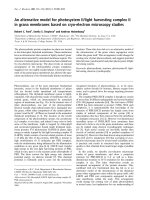
Figure 1.11 In situ TEM images recorded during the process of nanowire growth. (a) Au
nanoclusters in solid state at 500 °C; (b) alloying initiates at 800 °C, at this stage Au exists
in mostly solid state; (c) liquid Au/Ge alloy; (d) the nucleation of Ge nanocrystal on the
alloy surface; (e) Ge nanocrystal elongates with further Ge condensation and eventually a
wire forms (f). (Wu, Y.Y. et al. J. Am. Chem. Soc. 2001, 123, 3165)
The three stages can be clearly identified by TEM images:
(I)
Alloying process (Figure 1.11(a)–(c)): Under 900 ˚C the Au metal
remains solid without Ge vapor. With an increasing amount of Ge vapor
condensation and dissolution, Ge and Au form an alloy and liquefy.
(II)
Nucleation, (Figure 1.11(d)–(e)): As the concentration of Ge increases in
the Au-Ge alloy droplet, the process of nucleation of the nanowire begins.
The nucleation generally occurs at a Ge weight percentage of 50–60 %
from the volume change.
Chapter 1 Introduction
24
(III)
Axial growth (Figure 1.11(d)–(f)): Once the Ge nanocrystal nucleates at
the liquid/solid interface, further condensation/dissolution of the Ge
vapor into the alloy increases the amount of Ge precipitation from the
alloy. The incoming Ge vapors diffuse and condense at the solid/liquid
interface so that it is suppressing secondary nucleation events and pushed
forward (or backward) to form nanowires.
Figure 1.12 A series of video frames grabbed from observations of GaN decomposition at
1050 °C, showing the real-time GaN nanowire growth process. The number on the bottom
left corner of each frame is the time (millisecond). (Stach, EA et al. Nano Lett. 2003, 3, 867)
In 2003, Yang’s group directly observed the growth of GaN nanowires via a
self-catalytic VLS mechanism using
in situ
TEM again [23]. The series of video
frames grabbed from observations of the GaN decomposition processes at elevated
Chapter 1 Introduction
25
temperatures is presented in Figure 1.12, which show these GaN nanowires nucleate
and grow from Ga droplets formed during thermal decomposition of GaN at
elevated temperatures in a vacuum. This experiment further demonstrates the
powerful capabilities of
in situ
TEM for observing real time reaction process and
confirming the validity of the proposed mechanism.
1.3.4.3 In situ measurement of the properties of individual nanostructures
Characterizing the properties of individual nanostructure is crucial for
obtaining information specific to the nanostructure, as opposed to information
averaged out or at a large area. Based on electric field induced resonance excitation,
Wang Zhonglin’s group have developed a new experimental approach for
characterizing the mechanical properties of nanofibers [24] and the work function at
the tip of a single carbon nanotube [25] using
in situ
TEM.
They first manufactured nanobelt with diameters of 50-100 nm and length of
5-10 µm. A TEM specimen holder is specially designed for applying a voltage
across the nanobelt and its counter electrode. One end of the nanobelt is glued on the
copper wire, and the other end stands freely near the counter electrode. An
oscillating voltage with a tunable frequency is applied to the nanobelt. When the
frequency of the applied voltage matches the natural vibration frequency of the
nanobelt, mechanical resonance of the nanobelt can be induced. Thus the bending