Optimal control issues related to the hard disk drive servo systems
Bạn đang xem bản rút gọn của tài liệu. Xem và tải ngay bản đầy đủ của tài liệu tại đây (1.25 MB, 167 trang )
OPTIMAL CONTROL ISSUES
RELATED TO THE HARD
DISK DRIVE SERVO SYSTEMS
ZHONGMING LI
DEPARTMENT OF ELECTRICAL AND COMPUTER
ENGINEERING
NATIONAL UNIVERSITY OF SINGAPORE
2000
OPTIMAL CONTROL ISSUES
RELATED TO THE HARD
DISK DRIVE SERVO SYSTEMS
BY
ZHONGMING LI
A THESIS SUBMITTED
FOR THE DEGREE OF DOCTOR OF PHILOSOPHY
NATIONAL UNIVERSITY OF SINGAPORE 2000
Acknowledgments
I would like to express my greatest gratitude and sincere thanks to my supervisors,
Professor Ben. M. Chen, Dr. Guoxiao Guo and Professor T. H. Lee, for their in-
valuable supervision and support to my study in National Universit y of Singapore.
It is simply impossible for me to finish this thesis without their kind patience,
tremendous encouragement and enlightening discussions.
I would also like to thank Mr. Kexiu Liu, Mr. Xinmin Liu, Mr. Weilu Wang,
Mr. Daowei Wu, Mr. Qi Hao and other postgraduate students in Department
of Electrical Engineering of National University of Singapore and Data Storage
Institute. They have shared with me a lot of invaluable ideas and kno wledge,
while their friendship has brought much joy during my period of postgraduate
research. I am also thankful to the National University of Singapore for providing
the research scholarship to support my Ph.D. study.
Finally, I want to thank my wife, Zhang Ye, and my parents for their endless love,
support and encouragement.
i
Summary
The magnetic hard disk drive (HDD) as an important data-storage medium has
seen a 100% annual growth rate of a real density in the past few years. This trend
has been supported by the steady increase of the track density, which is mea-
sured by track-per-inch ( or TPI) and data density. The improved servo control,
compared with other ways of increasing the track density such as reducing the
vibration via thicker and alternativ e disk, fluid dynamic bearing spindle motors,
higher bandwidth or dual stage actuators, multi-sensing technology and etc., is the
most cost-effective way. Thus to impro ve the servo design in the hard disk drives
is the first choice and last band aid, for supporting the TPI growth.
This thesis presents some new control design methods for HDD servo systems. We
have studied the robust and perfect trac king (RPT) design in both the continuous-
time and discrete-time domains. Also the H
2
optimal control has been studied to
ac hieve the highest tracking accuracy. All the different designs have been applied
to two kinds of hard disk drive serv o systems, namely the single-stage actuator
system,inwhichthevoicecoilmotor(VCM)hasbeenbeusedinvirtuallyall
commercial disk drives until now, and dual-stage actuator system, in which a
secondary milli or micro actuator rides piggyback on top of the VCM and works as
a fine positioning actuator. The dual stage servo is regarded as the key technology
to support the TPI growth breakthrough in the future.
Robust and Perfect Tracking Control, a newly-developed control design method,
is the first control method we considered. In RPT design, we cast the overall
HDD servo system design into a RPT design framework. A first order dynamic
measurement feedback controller is then designed to achieve the robust and perfect
tracking for any step reference. Our controller is theoretically capable of making
ii
the L
p
-norm of the resulting tracking error with 1 ≤ p<∞ arbitrarily small in the
face of external disturbances and initial conditions. Some trade-offs are then made
in order for the RPT controller to be implementable using the existing hardware
setup and to meet physical constraints such as sampling rate and the saturation
of control in the system. The implementation results of the RPT controller are
compared with those of a PID controller. The results show that our servo system
is simpler and yet has faster seeking times, lower overshoot and higher accuracy.
Later the RPT design is applied to the dual-stage actuator hard disk drives. We
considered two different control strategies in the dual-stage actuator hard disk
drives. One is to apply robust and perfect tracking to VCM actuator and the
conventional PID design to the micro-actuator. Another design is to apply the
robust and perfect tracking to the micro-actuator, and conventional design to VCM
loop. These two control designs both show higher performances than the single-
stage actuator system.
The emphasis of the second half of this thesis is the application of H
2
optimal
control to investigate the performance limit for track following operation, which
is traditionally evaluated as Track Mis-registration (TMR) or equivalently Track
Per-Inch (TPI). Through analysis, we established that minimizing the closed-loop
H
2
norm considering the noise and disturbance models can minimize the TMR.
Therefore an H
2
control approach by solving the AREs for the non-regular H
2
optimal control problem, is applied towards the minimization of the TMR. Both
single-stage actuator case and dual-stage actuator are considered and the numer-
ical examples for these cases are studied. The control designs are compared with
the conventional PID control as well. Furthermore, to deal with the control satura-
tion due to the limited displacement range of the secondary stage actuator, we also
studied the H
2
optimal control design with the PQ method together. Compared
iii
with existing design methods, the proposed methods do not need the tedious con-
troller parameter tuning, and the optimal tracking performance is guaranteed by
the design method. Although the control designs were tested only on a dual-stage
servo loop with the piezo-electrically actuated suspension, the method is generic,
and should be applicable to other types of dual stage actuators such as MEMS
based actuated slider and actuated head without much glitch.
iv
Contents
Acknowledgments i
Summary ii
1 Introduction 1
1.1 BackgroundandMotivations 1
1.2 HardDiskDrive(HDD)ServoMechanism 8
1.3 ContributionsAndOrganizationsofThesis 12
2 Modeling And Iden tification of Hard Disk Drive Actuators 16
2.1 Steps of System Identification 17
2.2 Dual-actuatorStructureinHardDiskDrives 20
2.3 Modeling And Iden tificationofMicro-actuator 21
2.4 TheMicro-actuatorModel 24
2.5 Modeling And Iden tificationofVoiceCoilMotor 26
2.6 Summary 32
v
3 Preliminary 33
3.1 SpecialCoordinateBasis(SCB)[100] 33
3.1.1 Transformationofcontinuous-timesystemusingSCB 34
3.1.2 PropertiesofSpecialCoordinateBasis 37
3.2 RobustandPerfectTracking(RPT)Control 39
3.2.1 StatefeedbackCase: 42
3.2.2 SolutionstoMeasurementFeedbackCase: 45
3.3 H
2
OptimalControl 50
3.3.1 H
2
OptimalControlProblem 52
3.3.2 Infima of H
2
optimalproblem 53
3.3.3 TheExistenceConditions 56
3.3.4 H
2
Suboptimal State and Measurement Feedbac k Control . . 58
3.4 Summary 59
4 Robust and Perfect Tracking Control: Single-stage Actuator Case 60
4.1 Introduction 60
4.2 Control System Design Using the RPT Approach 62
4.3 ImplementationResults 73
4.3.1 TrackFollowingTest 73
4.3.2 PositionErrorSignalTest 75
vi
4.4 Conclusion 77
5 Robust and Perfect Tracking Control: Dual-stage Actuator Case 81
5.1 Introduction 81
5.2 ControlStructureofDual-stageActuator 83
5.3 Robust and Perfect Tracking C ontrol Design of Dual-stage Actuator
(I) 84
5.3.1 SystemModels 84
5.3.2 IndividualServoLoopControllerDesign 87
5.3.3 ImplementationResults 88
5.4 Robust and Perfect Tracking C ontrol Design of Dual-stage Actuator
(II) 92
5.4.1 Robust and Perfect Tracking Control for Discrete-time Systems 92
5.4.2 RPTDesignforDual-stageActuator 97
5.4.3 SimulationResults 99
5.5 ConcludingRemarks 103
6 H
2
Optimal Control Towards The Highest TPI 105
6.1 Introduction 105
6.2 TMR and H
2
OptimalControlProblem 107
6.3 H
2
Output Feedback Optimal Problem and Controller Design . . . 110
vii
6.3.1 ControlDesignforRegularCase 110
6.3.2 ControlDesignforSingularCase 112
6.3.3 OptimalControlDesignProcedureSummary 113
6.4 Single-StageActuatorCase 115
6.5 Dual-StageActuatorCase 120
6.6 Dual-stage Case: H
2
DesignUsingPQMethod 124
6.7 SummaryandDiscussion 128
7 Conclusions and Suggestions 129
7.1 Conclusions 129
7.2 SuggestionsForFutureWork 131
Bibliography 133
A Author’s Publications 151
A.1 JournalPublications 151
A.2 ConferencePublications 151
viii
List of Figures
1.1 AharddiskdrivewithaVCMactuatorservosystem 8
1.2 Illustrationofservomechanismindiskdrive 10
2.1 Modelingprocess 17
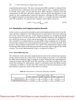
2.2 Value of loss function for models with differentorders 25
2.3 Modelvalidationtest 26
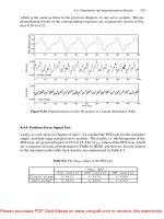
2.4 Frequency response of micro-actuator model and measurements . . 27
2.5 FrequencyresponseofVCMmodel 32
3.1 Illustration of H
2
optimalproblem 52
4.1 FrequencyresponseofVCMmodel 66
4.2 Responses of the closed-loop systems with parameterized RPT con-
troller when ε =1. 69
4.3 Responses of the closed-loop systems with parameterized RPT con-
troller when ε =0.01 69
ix
4.4 Responses of the closed-loop systems with parameterized RPT con-
troller when ε =10
−5
. 70
4.5 Step response of the closed-loop system with the discretized RPT
controller. 71
4.6 Step responses of the closed-loop system with different resonant fre-
quencies 71
4.7 Output response of the closed-loop system due to 55Hz run-out
disturbance 72
4.8 Output response of the closed-loop system due to 120Hz run-out
disturbance 72
4.9 Implement ation result: Step responses of closed-loop systems with
RPTandPIDcontrollers. 76
4.10 Implementation result: Closed-loop frequency response of system
withRPTcontroller. 78
4.11 Implementation result: Closed-loop frequency response of system
withPIDcontroller. 78
4.12 Implementation result: Histogram of the PES test with the RPT
controller. 79
4.13 Implementation result: Histogram of the PES test with the PID
controller. 79
5.1 Prototypedual-stageactuator 85
5.2 Bodeplotofprimaryactuator(estimatedaneexperimental) 86
x
5.3 Bodeplotofmicro-actuator(estimatedaneexperimental) 86
5.4 Photographofexperimentsetup 88
5.5 Onetrackseekusingdual-stageactuator 89
5.6 Threetrackseekusingdual-stageactuator 90
5.7 HistogramofPESreadingduringtrackfollowing 91
5.8 Closed-loopbodeplotofdual-stageactuatorsystem 91
5.9 dual-stageactuatorservosystemwithweightingfunctions 98
5.10Simulationdiagramofthedual-stageactuatorsystem 101
5.11Timeresponseofdual-stageactuatorinsample-datasystem 101
5.12Micro-actuatorcontrolsignalinsample-datasystem 102
5.13Measuredstepresponseinimplementation 102
5.14Measuredcontrolsignalofmicro-actuator 103
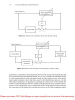
6.1 Typicalharddiskdriveservosystem 108
6.2 Simplified disk drive servo system with process d isturbance and noise108
6.3 H
2
outputfeedbackproblemofgeneralHDDs 108
6.4 BodeplotofVoiceCoilMotor(VCM) 116
6.5 H
2
andPIDcontrollersinsingle-stagecase 116
6.6 Bode plot of compensated open-loop systems by H
2
and PID in
single-stagecase 117
xi
6.7 Functions of sensitivity and complementary sensitivity by H
2
and
PIDcontrolinsingle-stagecase 117
6.8 Step responses of compensated system by H
2
andPID 118
6.9 Spectrum of true PES by H
2
controlsingle-stagecase 118
6.10 Histogram of true PES by H
2
controlinsingle-stagecase 119
6.11 Simulated TMR against the controller parameters’ variation 120
6.12 H
2
outputfeedbackproblemofdual-stageactuator 120
6.13BodeplotofMicro-actuator(MA) 121
6.14 Bode plots of VCM controller, micro-actuator controller and open
loopcompensatedsystem 122
6.15 Histogram of true PES by H
2
indual-stageactuator 122
6.16 Step response of H
2
compensatedsystemindual-stagecase 123
6.17 H
2
andPQmethodcompensatedsystemblockdiagram 125
6.18 Step responses of H
2
usingPQmethodcompensatedsystem 126
6.19 Bode plots of controllers and open loop transfer functions by H
2
usingPQmethod 127
xii
List of Tables
6.1 Summaryofcontrollerperformances 127
xiii
Chapter 1
Introduction
1.1 Background and Motivations
Since 1956, when the firstdiskdriveIBMRAMDACwithonly5-MBcapacityin
24-inch disk was introduced, the magnetic recording technology has been going
through a series of rapid transformations. At the same time, the areal densities
have increased dramatically. The recording densities have gone up more than 100
times and data access performance has gone up by at least 15 times in the last two
decades [87]. Nowadays, the magnetic hard disk drives have become the dominant
storage technology for information processing systems and have been applied in
suc h diverse applications from servers for large enterprise computers to desktop
and laptop computers. With the rapid development of the data storage capacity
and low cost, the hard disk drive is even considered as o ne of the key components
in the future consumer electronics, such as, to store the digital video and a udio
data in so-called hard disk recorder (HDR) [96].
The rapid evolution of magnetic hard disk drives in form factor, performance and
cost during the past 20 years has been the direct result of many technological
1
CHAPTER 1. INTRODUCTION
innovations applied to these products. These innovations include the magneto-
resistive heads for the areal densities above 20 GBits/in
2
, PRML data channels for
the media data rates exceeding 14 MBytes/sec, mechanical improvements for 3.5-
inch, 2.5-inch and smaller form factor designs, the spindle speed exceeding 7000-
10000 RPM even above 15000 RPM, increased reliabilities as measured in MTBF
(Mean-Time Between Failure) above 1 million hours, and finally t he decreasing
production cost [57, 34, 35, 36].
As the most imp ortant specification for hard disk drives, the areal density in-
crease is required to satisfy the demand for larger capacity hard disk driv es. The
compound growth rate of the areal density is astonishing 60%, even up to 100%
since 1997, driven by the progress of advanced magnetic sensors, thin film metal
media and PRML channels. At the same time, the wide use of personal computers,
laptops and handhold computers drives the form factor to be smaller and smaller,
from 3.5 inch, 2.5 inch, to even smaller than 1 inch.
Furthermore, the increase of the track density is exp ected to be larger than that of
bit density due to several reasons of magnetic recording and data transfer problems.
Currently, the disk capacity in 3.5-inch disk drives is above 180 GB, and that in
2.5-inch disk drives with 3 disks is more than 20 GB. It is estimated that the disk
capacity will reach 360 GB in the year o f 2005.
When the performance of hard disks is being increased, some obstacles must be
overcome. One obstacle in increasing track density is how to reac h the high head-
positioning accuracy in track-following, which is 8-10 % of the track width. When
the areal density is projected to be higher than 100 GB/in
2
by the year of 2005, the
positioning accuracy is even projected to be approaching about 0.01 µmatthesame
time [35, 125]. Another main obstacle is the data transfer rate limitation. There
2
CHAPTER 1. INTRODUCTION
are many possible ways to improve it, and both of the disk rotational speed and the
head seeking time are importan t design factors. Recently, the access time has been
improving rapidly. It is projected to be 2-4 ms by the year of 2005, while the seek
time is projected to be ev en smaller [125]. As a result of above specifications, the
servo bandwidth of the hard disk servo loop will be increased from currently about
1 kHz to above 4 kHz in the coming serval years. According to the requirements
of the hard disk servo mechanism, the head positioning servo must suppress both
the external and the internal disturbances during track-following, allow the swift
and smooth settling and access the target track quickly.
As a summary, to meet the specification of the high performance hard disk drives,
the control objectives of the servo design in hard disk drives should include: (1)
increase the bandwidth of servo loop; (2) develop a high speed and robust seeking
servo, and (3) dev elop a smooth settling servo. All the new progresses of research
work in the hard disk servo are all currently focused on these three objectives.
Among these targets, increasing the servo bandwidth is crucial to improving the
positioning accuracy. To increase the bandwidth, there are many methods that
have been presented. Most of them can b e grouped into three categories: loop
shaping, dual-stage actuator servo and multi-sensing servo [18, 125]. Let’s look at
the loop shaping method at first. Mainly, there are two obstacles to increase the
bandwidth. One is the sampling frequency, and the other is the mechanical reso-
nance. The sampling frequency of the 3.5-inch hard disk drives has been increasing
to meet the development of the track densit y, and most recen t rate is about 20 kHz.
On the other hand, it is not easy to increase the mechanical resonance frequency of
the VCM arm assembly in the disk drives, which is about 4 kHz. So generally, the
notc h filter has been widely used to compensate for the resonance. The concept of
3
CHAPTER 1. INTRODUCTION
using the notch filter is to assure stability margin based on the small gain theorem.
But its drawback is the phase shift around the crossover frequency, that limits the
increase of the servo bandwidth. Recently, the phase characteristics of the hard
disk plant ha ve been taken into account. Since the first resonance mo de is caused
by the actuator inertia and stiffness of pivot bearing, its phase characteristics can
be easily estimated [125]. Based on the comparatively accurate estimation of the
phase characteristics, the higher bandwidth can be achieved by many methods,
such as, adaptive sliding mode(see e.g., [118, 119], LQG/LTR (see e.g., [117]) and
so on. But due to the limitations of these control design methods, such as high
order of the controller, the difficulty of parameter tuning and etc., there is still the
need to study and apply the newly developed control methods in the hard disk
serv o to meet the higher performance requirement.
The dual-stage actuator is considered as another solution to the problem of in-
creasing the servo bandwidth. The dual-actuator method to increase bandwidth
refers to the case that there is a small actuator mounted on a large conventional
voice coil motor (VCM) actuator. This small actuator is referred as the fine or
secondary actuator and the large actuator is referred to as the coarse or primary
actuator. The dual-stage actuator structure has been used in optical disk drives
for a long time. Now it is drawing more and more in terests among the hard disk
drive servo researc h society. In such a serv o system, the track seeking should be
performed by the VCM alone as in the single actuator system. The micro-actuator
will perform the high-bandwidth, high precision control of the slider and will not
to suffer from friction. The position measurements from the micro-actuator will
be used in the servo loop to achieve the desired high bandwidth and tracking accu-
racy. As a result, it is quite possible for the dual-stage actuator to achieve above
2 kHz crossover frequency. There have been many research activities of dual-stage
4
CHAPTER 1. INTRODUCTION
actuator servo in last few years. Many methods, such as the conventional PID
control, optimal LQG/LTR (see e.g., [43, 62]) and newly presented PQ method
(see e.g., [103]) and so on, have been applied.
The last method to increase the servo bandwidth is the multi-sensing servo design.
In this design, the head suspension assembly is considered as a kind of flexible
structure with many vibration modes. A natural way to control the structure is to
have the states available as possible and use a state feedback method. There have
been several attempts of adding an acceleration sensor or a strain gauge [110]. The
recently technologies for multi-sensing design also include the multi-rate control,
zero phase error feed-forward servo (ZPETC) and the perfect tracking control
(PTC). First, the multi-rate control utilizes the fact that there is no restriction
of the sampling period of the control signal. As a result, the sampling period of
the control input can be much shorter than that of the position signal. There
have been several papers o n the multi-rate control and there are two methods that
utilize the multi-rate techniques. The first is to use an observer which outputs
an estimated position signal 2-4 times during one sampling period. Its benefi tis
to recover phase shift caused by a zero-order holder. The other approach is the
multi-rate feed-forward design [48]. Secondly, the zero phase error feed-forwa rd
servo is useful for compensating the phase to zero, but there is slightly gain down
in high frequency. Combining the ZPETC method with the multi rate control,
the tracking capability can be improved. The last one, which is called the perfect
tracking control (PTC), a lso uses the feature of the multi-rate output, and can
achieve fast seeking time [29, 125].
To achieve better performance of the hard disk servo, the smooth settling problem
is another important issue in which the exciting of resonance should be avoided
5
CHAPTER 1. INTRODUCTION
in the existence of various initial conditions. Recently published techniques of
smooth settling are the mode-switching control (MSC) with initial value com-
pensation (IV C), and advanced IVC design considering the mec hanical resonance
[126, 128]. The MSC methods have been applied to many motion control fields,
such as CD and XY tables. In HDD, the issue of the MSC is how to switch servo
with a smooth transient response. The advanced IVC design with mechanical res-
onance consideration is a frequency domain design method, that has lower power
to excite the mechanical resonance modes than the mentioned method above. An-
other proposed method is so-called Structural Vibration Minimized Acceleration
Trajectory [91].
As we have discussed here, there are many challenges in the hard disk drive servo
research to achieve higher performance. In this thesis, the presented work is mainly
focused on the optimal control design for the track-following servo in the hard disk
drives. Our concern is to increase the servo bandwidth of the hard disk drive
systems via the optimal control methods. Since the dual stage actuator structure
is another main concern recently, all the control designs that we considered have
been applied to both the single-stage and dual-stage actuator hard disk drives. Our
goal of the control design also includes developing a control system under which
the overall closed-loop system has quick response and fast settling time. That is to
move the read/write head from the present track to a specified destination track in
minimum time and maintain the head as close as possible to the destination track
center while information is being read or written. Since there are uncertainties
in the identified model and exterior noise, w e need the closed-loop system to be
robustly stable under existing modeling errors and has enough noise attenuation.
Currently most of the hard disk drives use a combination of classical control tech-
niques, such as lead-lag compensators, PI compensators and notch filters. To meet
6
CHAPTER 1. INTRODUCTION
the new requirements b y the fantastic development of the hard disk driv es, novel
con trol design m ethodologies should be considered beyond these classical methods
above. So far many control approaches have been tried, such as LQG and/or LTR
approach (see e.g., [45] and [62]), H
∞
almost disturbance decoupling approac h (see
e.g., [14]), and adaptive control (see e.g., [88]) and so on. Although much work
has been done to date, there are still much space for the application of advanced
control methods. For example, the controller obtained via many methods are of
higher order, which are difficult to be used in the high sampling frequency embed-
ded systems. More studies need to be conducted to use recently developed control
methods to achieve better performance of the hard disk drives.
Another concern of our work is tracking performance limit of the hard disk drive
servo systems. As we know, Track Mis-registration (TMR) is used to measure the
tracking accuracy of the whole HDD servo systems. It is defined as 3 times of σ
pest
s,
where the σ
pest
is the standard deviation of the true position error signal (true
PES). From the definition, we could find that the less TMR is, the higher accuracy
theharddiskcanreach. Inthesameway,thelessTMR,thehigherTPIcanbe.
For a given mechanical system, improving the servo design to achieve a higher
tracking accuracy is one of the most cost effective way among various solutions.
To minimize the 3σ
pest
, which determines the read/write tracking misregistration
(TMR), many con trol methods, suc h as LQG/LTR (see e.g., [62, 117]), optimal
control (see e.g., [78, 69, 124]), robust control (see e.g., [33]), multi-rate control (see
e.g., [29, 17, 48]) have been considered so far. However, the pe rformance limit, e.g.,
the lowest TMR and the highest TPI, that a linear controller can achieve has not
be fully investigated yet. How to achieve the highest TPI, or equivalently how to
obtain the minimized TMR by linear control method remains to be an interesting
topic. In this thesis, this specific problem has been studied and the corresponding
7
CHAPTER 1. INTRODUCTION
Figure 1.1: A hard disk drive with a VCM actuator servo system.
control design has been developed.
1.2 Hard Disk Drive (HDD) Servo Mechanism
In this section, the structure and servo mechanism of hard disk drives will be briefly
reviewed.
As shown in Fig.1.1, the rotating disks coated with a thin magnetic layer or record-
ing medium are written with data in concentric circles. Each concentric ring on the
surface on which data are recorded is referred to as a track. Data are written with
a head, which is a small horseshoe shaped electro-magnet with a very thin gap.
The e lectromagnet remains positioned only several micro-inches abo ve the record-
ing medium on an air-bearing surface (ABS) (often referred to as a slider), and
the gap of the energized electromagnet produces a strong magnetic flux field that
magnetically polarizes the recording medium, an operation called wr iting.Once
polarized, the recording medium remains so until being rewritten. Hence, the disk
drives are called nonv olatile storage. Besides being connected to a high-speed,
bipolar current source for writing, the head is also connected to a high-speed
8
CHAPTER 1. INTRODUCTION
preamplifier, the output read from the di sk surface into detected digital data [28].
The width (in the direction of a disk radium) of the gap determines the trackwidth,
whic h can be expressed by the track density, in track-per-inch (TPI). To determine
the storage capacity of a disk drive, we need to define the bit density,thenumber
of bits that can be stored along an unit distance of a track, usually quoted in bits
per inch (BPI) or bits per millimeter. Areal density,isdefined as the product of
BPI or TPI. Finally, to find the storage capacity, we multiply aerial density by
the available surface area for each disk surface.
As per the data transfer rate, the disk rotation and bit density together deter-
mine the data rate of the disk drive. Typical date rate varies from one to serval
megab ytes per second. In fact, in the disk drives with more than one disk surface,
the heads are most often positioned in unison such that a track defines a cylinder
corresponding to N tracks of total data for N heads. AcylinderofdataisthusN
times the total track capacity.
In the hard disk servo, the output of the position channel, that is the position error
signal (PES), is a signal proportional to the relative difference of the positions of
the center of the servo head and the nearest track center. Thus, the position
error signal is a periodic function of actuator position x for the stationary and
ideal track cen ters. The PES contains two sources of the motion: that of the
actuator and that of the disc surface. The pattern used on the servo surface is
designed in concert with a demodulation scheme, such that when read back, the
signals infer the head position relative to the nearest track center. T he location of
the pattern on the surface determines where the track center will be. Two basic
t ypes of demodulation are employed: peak detection and area detection. At the
same time, all the PES channels suffer degradation in performance under non ideal
9
CHAPTER 1. INTRODUCTION
Figure 1.2: Illustration of servo mechanism in disk drive
conditions.
The head-positioning servo mechanism in a hard disk provides a mean for locating
a set of read-write heads in fixed radial locations over the disk surface and allowing
the re-positioning of these heads from one radial location to another. Fig. 1.2 shows
the different stages of the position mechanism inside the hard disk drives, that could
be defined as, track seeking, track settling and track following. In the past two
decades, most of the work has been focused on the p e rformance improvement of
track seeking and track following[87, 28]. The smooth track following problem
has not drawn to o much attention until recent few years.
In general, track seeking means the mode that the R/W heads are moved from the
present trac k to a specified destination track in minimum time using a bounded
control effort. Often the access time is used to evaluate the seeking performance
and must be minimized within the limits of technologies and the intended cost of
the machine. Thus the optimal control, non linear con trol (e.g. bang-bang, PTOS,
etc.) and other techniques are used to provide the minimum seek time.
10