An enhance framework on hair modeling and real time animation
Bạn đang xem bản rút gọn của tài liệu. Xem và tải ngay bản đầy đủ của tài liệu tại đây (1.41 MB, 52 trang )
AN ENHANCE FRAMEWORK ON HAIR MODELING
AND REAL-TIME ANIMATION
LIANG WENQI
NATIONAL UNIVERSITY OF SINGAPORE
2003
AN ENHANCE FRAMEWORK ON HAIR MODELING
AND REAL-TIME ANIMATION
LIANG WENQI
A THESIS SUBMITTED
FOR THE DEGREE OF MASTER OF SCIENCE
DEPARTMENT OF COMPUTER SCIENCE
SCHOOL OF COMPUTING
NATIONAL UNIVERSITY OF SINGAPORE
2003
Acknowledgements
First of all, I would like to thank Dr. Huang Zhiyong. He has been continuously
providing me invaluable advice and guidance throughout the course of my study. It is
just impossible for me to complete this thesis without his sharing of ideas and expertise
in this area.
I would also like to thank School of Computing, which gives me the opportunity and
provides me all kinds of facilities that make my thesis possible.
I
Table of Contents
1. Introduction
1
2. Previous Works
5
3. U-Shape Hair Strip
9
4. Animation
23
5. Collision Detection and Response
31
6. Hair Modeling
38
7. Conclusion
44
Reference
45
II
Summary
Maximizing visual effect is a major problem in real-time animation. One work was
proposed on real-time hair animation based on 2D representation and texture mapping
[Koh00, Koh01]. Due to its 2D nature, it lacks of the volumetric effect as the real hair.
This thesis presents a technique to solve the problem. The hair is still modeled in 2D
strip. However, each visible strip is warped into U-shape for rendering after
tessellation. Alpha and texture mappings are then applied to the polygon meshes of the
U-shape. Note that the U-shape is not explicitly stored in the data structure. Because of
the U-shape technique, we also adapt the collision detection and response mechanism
in the former method. There are collisions between hair strips and other objects, e.g.
scalp and shoulder, and the self-collisions of hair. Finally, a hair modeling function
that is capable of modeling different hairstyles is also implemented.
Keywords: Hair Modeling, Hair Animation, Collision Detection, Collision Response,
and Real-time Simulation
III
1. Introduction
In this chapter, we give a brief background about the problems arising in hair modeling
and animation. Following this, we present the objective of the work. Finally, we
outline the organization of the thesis.
1.1 Background
Hair modeling and animation have been a challenging problem for years. This is
mainly because of the unique characteristics of human hair.
On average human being has 100,000 to 150,000 hair strands on his head. Practically
in order to obtain a sufficiently good animation, it is necessary to use about 20,000 hair
strands for a high quality 3D head model. Around 20 segments or more will be used
for each hair strand to make it look smooth. This gives us about 400,000 line segments
in the entire hairstyle. Comparatively, a high quality 3D human head uses only about
10,000 polygons and a body with clothing requires another 10,000 to 40,000 polygons.
Consequently, hair will potentially consume a large potion of computation resource in
human animation, despite being only a small part on a virtual character.
Nevertheless, the large count of individual hair strands gives us even more problem.
Having thousands of individual hair strands in a single hairstyle, it is very tedious to
specify these hair strands one by one. Therefore an automatic process is necessary to
release people from this job.
1
Moreover, in order to model the dynamics of hair motion correctly, collision detection
and collision response during hair movement must be considered as well. Due to the
large quantity of individual hair strands, precisely calculating and resolving the
collision is almost impossible in practice. Some sort of approximate calculation for
collision detection and collision response is therefore necessary.
Another problem is the small scale of an individual hair strand as compared to a single
image pixel. To cater for this, special rendering techniques are needed. In order to
produce visually realistic animation, it is important for these techniques to take the
complex interaction of hair, lighting and shadows into account. These are again
computation intensive problems.
Different techniques have been proposed to tackle these problems. Instead of modeling
hair individually, there have been works using trigonal prism based approach [Wata92,
Chen99]. Plante et al [Plan01] proposed a wisp model to approximate interactions
inside long hair. Unfortunately, these techniques are not suitable for real-time hair
animation. Recently, Koh and Huang [Koh00, Koh01] proposed a strip based approach
that animates in real-time. But because of the 2D strip used, it is unable to produce the
volumetric effect as real human hair.
All these motivated the work to be described in this thesis, which is to propose an
enhanced framework on hair modeling and real-time animation with improved visual
effect.
2
1.2 Objective
Our research is on the methods of hair modeling and animation. In the proposed
method, the goal is to achieve a real time rendering speed with a good visual quality.
In the previous work by Koh and Huang [Koh00, Koh01], a method based on 2D strip
has achieved real-time hair animation. However, the visual effect was not good enough.
In particular, it was unable to produce animation with volumetric effect as natural
human hair. The proposed method will solve this problem.
For hair modeling, designing new hairstyle from scratch is a tedious job. People need
to specify individual hair stands, which come in thousands, and define the relationship
among them. To release user from tedious work of designing hairstyles, the hair
modeling function in our method should provide a way to easily specify them. In
addition to that, different hairstyles must be designed interactively using the same
technique.
Nevertheless, to achieve real-time animation, overall performance of the framework is
also important. At the same time, to ensure physical plausibility, some sort of physical
model needs to be used to simulate the dynamics of hair model and collision must be
handled as well.
3
1.3 Thesis Outline
Chapter 2 briefly reviews the related existing work in the area of hair modeling and
animation.
Chapter 3 introduces the idea of improving visual effect. A method using U-shape hair
strips is proposed.
Chapter 4 illustrates the underlying Physics model that is used to simulate the
dynamics of hair.
Chapter 5 discusses collision detection and response implemented in our method.
Chapter 6 shows how a hairstyle is modeled in the framework.
Chapter 7 concludes the thesis with brief discussions on future work.
4
2. Previous Works
There are basically four problems to solve in order to produce realistic animated
synthetic actors with hair: hair modeling and creation, hair motion, hair rendering, and
collision detection and response [Dald93].
The modeling of hair specifies the geometry, distribution, shape and direction of each
of the hundreds of thousands of individual hair strands. Various methods have been
used to model human hair. Earlier work models individual hair strands as connected
line segments [Anjy92, Dald93]. There is also work using trigonal prism based
approach [Wata92, Chen99]. Plante et al [Plan01] proposed a wisp model for
simulating interactions inside long hair. In a trigonal prism based approach, hair
strands are clustered into wisps. Each wisp volume consists of a skeleton and a
deformable envelope. The skeleton captures the global motion of a wisp, while the
envelope models the local radial deformation. However, there is a lack of coherence in
motion among nearby wisps.
Recently, Koh and Huang presented a novel approach that explicitly models hair as a
set of 2D strips [Koh01]. Hair strands are grouped into 2D strips. Texture mapping is
used to increase the visual effect. The framework is capable of producing a real-time
hair animation. However it lacks of volumetric visual effect. Later in this chapter, this
framework will be described in detail. There are still a number of other approaches like
the ones using volumetric visualization techniques and 3D textures [Neyr98, Kong99]
and the lately proposal of modeling dense dynamic hair as continuum by using a fluid
model for lateral hair movement [Hada01]. However, they are not real-time.
5
As all motions are governed by laws of Physics, and almost all hair animation work is
based on some sort of physical model [Terz88]. Daldegan et al [Dald93] and
Rosenblum et al [Rose91] used a mass-spring-hinge model to control the position and
orientation of hair strand. Anjyo et al [Anjy92] modeled hair with a simplified
cantilever beam and used one-dimensional projective differential equation of angular
momentum to animate hair. Recently, Lee et al [Lee00] developed on Anjyo’s work to
add some details to model hairstyles.
An integrated system for modeling, animating and rendering hair is described in
[Dald93]. It uses an interactive module called HairStyler [Thal93] to model the hair
segments that represents the hairstyle. Hair motion is simulated using simple
differential equations of one-dimensional angular moments as described in [Anjy92].
Collision detection is performed efficiently with a cylindrical representation of the
head and body [Kuri93]. Detected collisions between hair strands and the body will
respond according to the reaction constraint method [Plat88]. However, due to the
complexity of the underlying geometric model of hair, the simulation of the hair
dynamics as well as collision detection and response could not be done in real-time
even after taking huge liberties with approximating the Physics model for animating
hair. In recent work of Chang et al [Chan02], a sparse hair model with a few hundred
strands is used. Each strand from the sparse model serves as the guide hair for a whole
cluster. Once an animation sequence is generated, additional hairs are interpolated to
produce a dense model for final rendering.
6
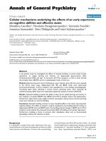
Now let us take a closer look at the work done by Koh and Huang [Koh00, Koh01]
that is most relevant to our work. To reduce the large number of geometric objects to
be handled, hair strip (Figure 2.1) is used to represent a group of hair strands. It is in
the shape of thin flat patch, which is modeled geometrically by NURBS surface.
A) One hair strip
B) All hair strips overlaying on the scalp
Figure 2.1. Hair modeling in strips from [Koh00]
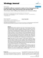
For rendering, the NURBS representation is tessellated into polygon mesh using Oslo
algorithm [Bohm80]. Finally, texture maps of hair images are applied on each surface
patch. The alpha map defines transparency and creates an illusion of complex
geometry to the otherwise “rectangular” surfaces and adds to the final realism (Figure
2.2).
The Physics model used is similar to the one proposed by Anjyo [Anjy92] and later
extended by Kurihara [Kuri93]. Hair strand is modeled as connected line segments and
polar coordinate system is used to solve the differential equations.
7
Collisions between hair strips and external objects are detected and handled explicitly.
Collisions in-between hair strips are avoided.
A) Texture map
D) Collection of hair strips
B) Alpha map
C) Resultant map
E) With texture and alpha maps applied
Figure 2.2. The strip-based hair model with texture and alpha maps from [Koh01]
8
3. U-Shape Hair Strip
In this chapter, we describe the framework in detail. We are going to propose a method
to enforce the volume effect for the simple strip based model. In subsection 3.1, details
of the U-Shape hair strip are to be discussed. Then, in subsection 3.2, the overall
structure of the implementation is to be addressed. And finally, results will be
presented in subsection 3.3.
3.1 U-Shape Hair Strip
Using only the basic 2D hair strip, the resulting hair model looks not volumetric.
Planting multiple layers of hair strips onto the scalp can of course solve this problem.
However with the presence of more hair strips, more computation power is needed to
animate these additional layers of hair strips, difficult to be real-time.
In order to enforce the volumetric effect without introducing additional hair strips, Ushape hair strips are used in the framework. The idea is to project the surface meshes
of a strip onto the scalp and insert 2 additional surface meshes by connecting the
original vertices and the projected vertices (Figure 3.1B). In order to enhance the
visual effect, texture and alpha maps are applied to both the original and the projected
polygon meshes (Figure 3.1D).
9
A) Tessellated polygon meshes
B) Polygon meshes with projection
C) Tessellated polygon meshes
D) Polygon meshes
with texture
with projection and texture
Figure 3.1. Illustration of U-shape polygon meshes
10
The boundary of the scalp is approximated using several spheres. Initially, a point in
the scalp is used as the projection center. Vertices of the polygon meshes are connected
with the projection center. The intersection of the connected lines and the boundary
spheres are taken as the projections of the vertices on the scalp. By connecting the
original vertices and the corresponding projections, the projected polygon meshes are
retrieved (Figure 3.2).
Figure 3.2. Demonstration of projecting polygon mesh onto scalp for deriving Ushape meshes
However, we found that using a point as the projection center could cause problems. It
is possible that two neighboring polygon meshes do not fully cover the scalp between
them. Figure 3.3A is the cross section view demonstrating the problem. Consequently,
part of the scalp is uncovered with hair when observing from certain direction.
11
A) Neighboring polygon meshes do not
fully cover the scalp
B) Neighboring projections
overlap each other
Figure 3.3. Use a sphere as projection center instead of a point to solve
the problem that two neighboring polygon meshes do not fully cover
the scalp between them
To overcome this problem, we are going to use a small sphere as the projection center
instead (Figure 3.3B). By using a sphere as the projection center, there will be some
overlapping between the projections of neighboring polygon meshes.
Once the projected polygon meshes are created, it may be necessary to modify them a
bit when one of the following undesired characteristics occurs:
•
The projection on the scalp is too far away from the original vertex.
When animating long human hair, the tail of the hair strands would be quite far away
from the scalp (Figure 3.4A). If the whole area were used for texture and alpha
mapping, the resulting effect would be quite unnatural.
12
A) Tail of the hair strip is too far away
from its projection
B) Modified hair strip projection
C) The shaded part on the left is the
reverse volume
D) Modified hair strip projection
handling reverse volume
Figure 3.4. The undesired characteristics and their solutions
13
•
By connecting the projection and the original vertex, reverse volume appears.
When projecting the hair strips, the projected polygon meshes are expected to be on
one side of the hair strips that face the scalp. However, as hair swings in the wind, it is
possible that the projected polygon meshes or part of them appear on the other side.
They are so called reverse volume (Figure 3.4C). It is obvious that this will give us
problem during rendering as the hair strip is twisted.
When either of these two undesired characteristics appears, it is necessary to modify
the projected polygon meshes. The approach that we use is described below.
Suppose A' is the projection of vertex A and it carries either of the undesired
characteristics. A' is then modified so that it carries the following three properties
(Figure 3.4B, Figure 3.4D).
1. Vector AA' is perpendicular to the polygon that A belongs to.
2.
AA' = C , where C is a preset constant.
3. The direction of AA' is set to be the same as the side of the hair strip that faces
the scalp.
14
3.2 Implementation
An object-oriented paradigm is adopted for the implementation of the proposed
framework by using Java™ SDK standard edition version 1.3.0_01 and Java3D™ 1.3
OpenGL version. Figure 3.5 below is an overview of the scene-graph structure of the
proposed framework for hair modeling.
Figure 3.5 Overview scene-graph structure of the proposed framework
15
On top of the scene-graph is a Virtual Universe, which contains all the objects. A
Locale is attached to the Virtual Universe to get a viewpoint of it. A BranchGroup
node is a container for other nodes, such as TransformGroups, Behaviors, Lights, and
Shapes etc. A Behavior node manipulates the interactions between users and the scenegraph. A TransformGroup node provides matrix transformation to all its children. A
Shape node represents an object in the scene. The form of the object is defined by
Geometry and Appearance, which are leaf nodes.
The position, orientation and scale of the Shapes are controlled by modifying the
transform matrix of their parent TransformGroups.
Keyboard and mouse interruptions from users are parsed via the Behavior nodes,
which in turn change the transform matrix of corresponding TransformGroup to rotate,
scale or move the objects.
Shadowing and lighting effects are achieved by the Light nodes.
The Head BranchGroup contains a baldhead, onto which hair strips are to be planted.
The Hair BranchGroup holds the list of hair strip objects. Each hair strip object stores
the information about its geometry coordinates, which is generated from its NURBS
control points, in the Geometry node. To improve visual effect, texture and alpha
mappings are applied and stored in the Appearance of the hair strip objects.
16
The calculation of the projected polygon meshes
Once the NURBS control points are tessellated into polygon meshes, each of these
polygon meshes is to be projected onto the scalp to form two projected polygon
meshes. The boundary of the scalp is approximated by a group of spheres. A smaller
sphere is placed in the middle of the boundary as the projection center. Let us call this
sphere S for simplicity in the following context.
Figure 3.6A shows an example of a tessellated polygon meshes. Horizontally adjacent
vertices of the polygon meshes are grouped into pair. For each pair of vertices, they are
connected to the center of S (Figure 3.6B). A point is located on S for each vertex in
the vertex pair. Let us take Figure 3.6C as an example to describe the property of these
newly located points. A and B is the vertex pair; and A' is the newly located point.
A is set to be the origin of the local coordinate system. The x-axis points the same
(
)
direction as vector AO . The y-axis is then set to be AB × AO × AO . The z-axis is set
to be pointing the same direction as AB × AO . The point A' carries the following three
properties:
•
A' is a point in the plane x-y.
•
The line that connects A and A' is tangential to S, and line AA' touches S
exactly at A'
•
The angle between AB and AO is smaller than the one between AB and AA' .
The corresponding point for B can be found in a similar manner.
17
A) A tessellated polygon mesh
B) Vertices connected to center of S
C) A local coordinate system is used
Figure 3.6 The calculation of the projected polygon meshes
Now we are ready to find the projection of the vertices on the scalp. The algorithm is
shown below. It recursively takes the middle point, until the projection is found.
18
A : A vertex on the tessellated polygon mesh
A' : The point on S found by the up-described procedure
Let X = A , Y = A' and ∆ be a preset threshold
While XY > ∆
Let Z be the middle point of X and Y
If Z is inside the boundary of the scalp
Y =Z
Else
X =Z
End
X is output as the projection of A
We now proceed to handle the undesired characteristics.
The first undesired characteristic could be easily detected by calculating the distance
between each vertex and its projection. The second undesired characteristic, the
reverse volume, could be detected as follows.
Let us take an example as in Figure 3.7. If the projection of a vertex, say A in Figure
3.7, could cause reverse volume, the angle between AA' and AB × AC would be
greater than 90 degree. A similar approach can be used for vertices at other positions.
19
Figure 3.7. The detection of reverse volume
If any of the undesired characteristics is detected for a vertex, its projection on the
scalp is to be modified as follows.
We will use Figure 3.7 again for easier illustration. Suppose A carries one of the
undesired characteristics. The vector AC × AB is calculated and its length is scaled to
a predetermined constant. Name this vector V . Let O be the origin of the universal
coordinate system. A' , the projection of A , is determined as follows: OA' = OA + V .
20