Design and characterization of interposers for high speed fine pitch wafer level packaged device testing
Bạn đang xem bản rút gọn của tài liệu. Xem và tải ngay bản đầy đủ của tài liệu tại đây (3.81 MB, 126 trang )
DESIGN AND CHARACTERIZATION OF INTERPOSERS
FOR HIGH-SPEED FINE-PITCH WAFER-LEVEL
PACKAGED DEVICE TESTING
Tan Pang Hoaw, Jimmy
(B. Eng. (Hons) NUS)
A THESIS SUBMITTED
FOR THE DEGREE OF MASTER OF ENGINEERING
DEPARTMENT OF ELECTRICAL AND COMPUTER ENGINEERING
NATIONAL UNIVERSITY OF SINGAPORE
2005
To My Family
ii
Acknowledgements
I would like to express my greatest appreciation to the following people for their help in
one way or another throughout the course of my research project, without them, this
Masters of Engineering (M.Eng) project would have been much more difficult. My
foremost appreciation goes to my supervisor, Dr. Mihai Dragos Rotaru from the Institute
of Microelectronics (IME), Singapore. He has given me tremendous help and guidance in
the course of this work. His insightful advice has always been invaluable. He has given
up a considerable amount of precious time and effort to guide me and at times, motivate
me when I was lost. He is very supportive and has been a great mentor to me. I am really
grateful to be able to work with him for the past few years.
I would also like to thank my NUS supervisors, Professor Leong Mook Seng and
Associate Professor Ooi Ban Leong. Prof. Leong has given me lots of invaluable
suggestions and advice on the research and has been very patient with me. He has always
showed interest in my research progress and taken time to understand problems that I was
facing. He is very approachable and friendly and was always there when I needed his
advice. Prof. Ooi has also been very supportive and helpful. I thank him especially for
going through my thesis in detail many times and guiding me along the way. He has
provided insight and excellent suggestions for my research.
iii
I am also grateful to my NWLP project team. Special thanks go to Prof. Andrew Tay,
Prof. David Keezer and Prof. Rao Tummala for their help and support.
Lastly, I would like to thank my family and friends. I am thankful to my parents, Michael
Tan and See Siew Kean, my brother, David and my sister, Janice, for their constant
support and love. I thank my great friend, Tan Lian Hing, for his tremendous help along
the way. Last but not least, in particular, my greatest thanks go to my fiancée (when I was
doing the research) /wife (when I am writing this), Yea Huey. She is lovely and
supportive as always. She has always been there when I was down. Without her, this
project would not have been easy.
iv
Table of Contents
Acknowledgements
Table of Contents
iii
v
Summary
vii
List of Figures
ix
List of Tables
xiv
Chapter 1
Introduction
1.1
Background
1.2
Project Objectives
1.3
Outline of Concept
1.4
Thesis Layout
1.5
Original Contributions
Chapter 2
Literature Review
2.1
Probe Cards Technologies
2.1.1
Considerations for Probe Cards
2.1.2
Epoxy Ring & Ceramic Blade Probe Cards
2.1.2.1 Epoxy Ring
2.1.2.2 Blade Cards
2.1.2.3 Epoxy Ring Vs Ceramic Blade
2.1.3
Micro-spring Probe Card
2.1.4
LIGA processed Micro Contact Probe
2.1.4.1 Contact Probe Requirements
2.1.4.2 Fabrication Process
2.2
Signal Integrity
2.2.1
Transmission Lines
2.2.1.1 Return Path and Switching Reference Planes
2.2.1.2 Reflections
2.2.1.3 Losses in Transmission Lines
2.3
Modeling Techniques
1
1
7
7
9
9
11
11
15
18
18
20
25
26
27
28
29
30
33
33
34
35
37
v
Chapter 3
MEMS based Interposer using Silicon as Substrate
3.1
Introduction
3.2
Modeling and Simulation
3.2.1
Results Analysis
3.2.1.1 Optimization
3.3
Summary and Discussions
39
39
43
45
53
57
Chapter 4
Elastomer based Interposer
4.1
Introduction
4.2
Modeling, Simulation and Measurement
4.2.1
Results Analysis
4.2.1.1 Trampoline
4.2.1.2 DUT Test Structure
4.2.1.3 Overall Test System
4.2.2
Measurements
4.3
Parametric Variation Study
4.3.1
Variation of the SMA Connector Transition Part
4.3.2
Variation of the Via Transition Part
4.3.3
Variation of the Short Traces on the Bottom Layer
4.3.4
Variation of the PCB Board Part
4.4
Summary and Discussions
58
58
66
68
69
70
72
78
81
82
88
90
99
104
Chapter 5
Conclusions and Recommendations for Future Works
5.1
Conclusions
5.2
Recommendations for Future Works
106
106
106
107
References
109
vi
Summary
In this thesis, novel designs of two unique interposers for the application of fine-pitch,
high-speed wafer-level packaged device testing have been proposed and studied. An
interposer is needed for the wafer level test because the fine pitch, high pin count, high
density of Inputs/Outputs (I/Os) and vertical compliance requirements have to be
accounted for. The interposer serves as the electromechanical interface between the
signal generator or test processor and the device under test (DUT). Both of the designs
were successfully characterized. One of proposed interposers is a MEMS based
interposer using silicon as the substrate and the other is an elastomer interposer. The
MEMS based interposer has special MEMS contacts to provide vertical compliance while
the elastomer interposer has a special elastomer mesh structure to achieve that.
Both the interposers were designed with careful consideration of the limitations in
electrical and mechanical aspects. To obtain better insight and appreciations of these
interposers, electrical characterization were performed with the aid of a numerical solver
(based on the finite element method). The possibility of optimizing the electrical high
frequency response of both was examined and carried out. After detailed characterization
had been made, the MEMS-based interposer was found to have limited bandwidth of 1
GHz and an insertion loss of 12 dB at 5 GHz, the target high-speed I/Os of the
specifications. Therefore, it is not suited for the required wafer level packaged (WLP)
vii
device test and was therefore not fabricated. In contrast, the characterization of the
elastomer-based interposer shows good high frequency response and it meets nearly all
the specifications required for the test. Therefore, a prototype of this interposer was
fabricated. A functional test of this prototype interposer was successfully carried out.
Measurements of the wafer-level packaged device using this interposer are compared to
the simulation results. A simulation model for the test is made up of a series of cascaded
models representing each components of the test, including the interposer, the wafer level
packaging interconnects and the DUT. Each of these models is represented by either their
simulated or measured S-parameters or an equivalent circuit. Without taking into the
account of the reflections and discontinuities at the interfaces between these components
in the overall cascaded test model and with assumption that the references at interfaces
are aligned, a good degree of accuracy of the simulated model was achieved compared to
the results of the measurements. This interposer shows a bandwidth of 5 GHz. Further
parametric variation study of the interposer was attempted. Quantitative and qualitative
studies showed that the most crucial part contributing to the signal degradation is the
design of the printed circuit board (PCB) part of the interposer. 75 % of the loss of the
overall test system is attributed to this board.
viii
List of Figures
Figure 1.1: Membrane probe, Leslie and Matta, 1988
3
Figure 1.2: Formfactor’s Microsprings contacts
4
Figure 1.3: Interconnects for wafer level packaged device
5
Figure 1.4: WLP test concept
6
Figure 2.1: Composition of semiconductor test equipment
12
Figure 2.2: Mechanical requirements
15
Figure 2.3: Electrical requirements
16
Figure 2.4: Multi-DUT memory probe card
18
Figure 2.5: Epoxy card with ring assembly
19
Figure 2.6: Blade probe card with blades attached
21
Figure 2.7: Low leakage probe card
21
Figure 2.8: Different types of ceramic blade probe cards
22
Figure 2.9: Edge sensor configurations
23
Figure 2.10: Ceramic blade types
23
Figure 2.11: Ceramic blade probe geometries
24
Figure 2.12: The changes on the new MicroSpringsII
27
Figure 2.13: Structure of conventional contact probe
29
Figure 2.14: Basic structure of a micro contact probe
29
Figure 2.15: LIGA process
30
Figure 3.1: Interposer for NWLP DUT test
41
Figure 3.2: Top view of the proposed MEMS based interposer (25 mm X 25 mm)
41
ix
Figure 3.3: Cross sectional view (section AA’ in Figure 3.2) of the proposed MEMS
based interposer (top 750 µm pitch side facing down)
42
Figure 3.4: Enlarged view of the layout of the compliant structure of the proposed MEMS
based interposer (100 µm pitch side in Figure 3.2)
42
Figure 3.5: Cross sectional view of the proposed MEMS based interposer showing the
build-up layers
44
Figure 3.6: The overall response of the proposed MEMS based interposer
45
Figure 3.7: Part A and Part B of the interposer (reference can be seen in Figure 3.2)
46
Figure 3.8: Part C, D, E models and cross sectional showing where they are (reference
can be seen in Figure 3.2)
47
Figure 3.9: S21s of the five parts (signal–power)
49
Figure 3.10: S21s of the five parts (signal-ground)
50
Figure 3.11: Five parts cascaded in ADS
52
Figure 3.12: Comparisons of the complete signal path transmission loss of signal-power
to signal-ground
52
Figure 3.13: Dielectrics in between the build-up layers
53
Figure 3.14: Insertion loss for Part B(BCB as dielectric, thickness 2 µm)
54
Figure 3.15: Insertion loss for Part B(SiO2 as dielectric, thickness 2 µm)
54
Figure 3.16: Insertion loss for Part B(BCB as dielectric, thickness 4 µm)
55
Figure 3.17: S21 of Part B with one of the reference planes taken (BCB as dielectric,
thickness 4.9 µm)
55
Figure 3.18: Comparison of capacitive parasitics of Part B between initial design (left)
and optimized design (right)
56
Figure 3.19: The much improved response of the optimized design of Part B
56
Figure 4.1: The test concept (cross sectional view)
59
Figure 4.2: Cross sectional schematic view of the test interposer
60
Figure 4.3: Cross sectional view showing the complete test signal transmission
60
x
Figure 4.4: Fabricated prototype test socket
61
Figure 4.5: Close-up view of the trampoline
62
Figure 4.6: Top view of the complete layout of the trampoline
62
Figure 4.7: Cross sectional view of the interposer showing the thickness of the layers and
the composition of the materials used
63
Figure 4.8: Top view showing the layout of the proposed elastomer interposer
64
Figure 4.9: Characteristic impedance of the designed microstrip
64
Figure 4.10: Top view of the top layer of the interposer showing dimensions
65
Figure 4.11: Bottom layer of the interposer showing the 100 µm pitch side
65
Figure 4.12: 3D models of the interposer with and without SMA connector showing
excitation ports
67
Figure 4.13: Simulated models
68
Figure 4.14: S21 comparison of interposer board part between with and without SMA
connector
69
Figure 4.15: The model of the trampoline showing excitation ports
70
Figure 4.16: Actual layout view of the trampoline
70
Figure 4.17: The DUT showing the CPW test structure
71
Figure 4.18: Transmission loss S21 of the DUT
71
Figure 4.19: System model for the WLP test showing four sets of components
(represented by either simulated data, measured data or equivalent model respectively) 73
Figure 4.20: Model and equivalent circuit for the Stretched Solder Column interconnect
74
Figure 4.21: Insertion loss comparison of the system setup on different lengths of the
CPW on the chip using BON as interconnects
75
Figure 4.22: Insertion loss comparison of the system setup on different lengths of the
CPW on the chip using SC as interconnects
75
xi
Figure 4.23: Insertion loss comparison of the system setup on different type of
interconnects mounting on the chip while using the short CPW on the chip
76
Figure 4.24: Insertion loss comparison of the system setup on different type of
interconnects mounting on the chip while using the long CPW on the chip
77
Figure 4.25: Return losses of the overall system of WLP test using the proposed
elastomer based interposer
78
Figure 4.26: Magnitude and phase of the insertion loss comparisons between simulations
and measurements results
79
Figure 4.27: Magnitude and phase of the return loss comparisons between simulations
and measurements results
80
Figure 4.28: SMA connector perpendicular to the PCB board
83
Figure 4.29: Tapered Design 1 & 2
83
Figure 4.30: Tapered Design 3 and Step Design 1
84
Figure 4.31: Various step designs with connectors
85
Figure 4.32: New design model for the interposer separated into two parts, the SMA
connectors transition part and the rest of the structures of the interposer
87
Figure 4.33: Insertion loss comparisons of new PCB board with/without connector design
to old design
88
Figure 4.34: New Design 1 of the via transition part (one additional via added)
88
Figure 4.35: New Design 2 of the via transition
89
Figure 4.36: Insertion loss comparisons of different via transition part designs
90
Figure 4.37: Trampoline model with two candidates for its equivalent circuit model (refer
to Figure 4.15 for the ports notation)
92
Figure 4.38: Comparisons of trampoline 3D model response to equivalent circuit models
93
Figure 4.39: Responses comparisons of trampoline to equivalent model
94
Figure 4.40: Comparison of magnitude of input impedance of trampoline to the
equivalent circuit model
95
xii
Figure 4.41: Impact on overall system insertion loss with changes made on the
capacitance in the equivalent circuit model of trampoline
97
Figure 4.42: Two designs of the tapered short traces (reference can be seen in Figure 4.12)
98
Figure 4.43: Comparisons for responses of different designs on the short traces
99
Figure 4.44: Comparison of old (original), new coplanar SMA connector design and the
new coplanar SMA connector design without the via transition and the bottom layer short
traces parts
100
Figure 4.45: Original and shortened model
101
Figure 4.46: Insertion loss S31 comparison between original and shortened versions of
the interposer
102
Figure 4.47: Insertion loss S42 comparison between original and shortened versions of
the interposer
102
Figure 4.48: Comparison for responses of original and shortened board size of the
interposer excluding the connector part
103
Figure 4.49: Insertion and return losses comparisons between interposer &DUT to
interposer board only
104
xiii
List of Tables
Table 1.1: Comparison of different probing technologies
4
Table 2.1: Epoxy vs. blade comparison
26
Table 2.2: Comparison of two different micro-spring contacts
26
Table 2.3: Requirements for micro contact probe
29
Table 2.4: General guidelines to minimize signal integrity problems
32
Table 3.1: Insertion loss for models at 10 GHz when reference was power plane
51
Table 3.2: Insertion loss for models at 10 GHz when reference was ground plane
51
Table 4.1: Simulated results for various step designs
85
Table 4.2: RLC extraction of the trampoline (at 100 MHz)
91
xiv
Chapter 1
Introduction
An interposer is required for the electrical high speed testing of fine pitch wafer level
packaged devices. It provides a solution to the required fine pitch, high density I/Os, high
pin count and vertical compliance specifications of the test. This interposer is to serve as
the electromechanical interface between the nano wafer level packaged (NWLP) device
chip under test (DUT) and the automated test equipment (ATE). Two interposer designs
have been proposed in this research work.
The first interposer is a MEMS-based interposer using silicon as substrate, while the
second proposed interposer is an elastomer-based interposer. Mechanical and electrical
constraints and limitations need to be taken care of in the design phase. In order to
produce reliable electrical test results, signal integrity at high frequencies will be the most
important issue to be investigated. The aim is to achieve minimum attenuation along the
propagating signal transmission paths. Therefore, good characterization of these
interposers are needed in order to accurately predict their high frequency performance.
1.1 Background
In today’s cost-effective oriented microelectronics industry, unnecessary packaging cost
can be avoided by rejecting defective components at as early stage as possible in a
1
production cycle. That is why complete direct current (DC), alternating current (AC),
functional testing at wafer level are increasingly important.
As the semiconductor technology moves to the submicron regime, the requirements
placed on the test probe cards have become increasingly stringent and challenging.
Implementation of highly reliable, efficient and cost effective probe cards becomes more
and more difficult with the conventional technology available because of the higher pin
counts and density per die. The earliest epoxy ring probe card has the limitations of poor
control over the interface’s electrical environment and fragility. The membrane probe
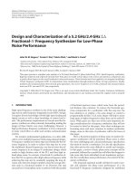
card shown in Figure 1.1 is an attempt to address these problems [21] [22]. It has many
advantages over epoxy needle probe card such as lower parasitic inductance, controlled
impedance tips, and improved mechanical reliability. However, it also has drawbacks
because of the additional force delivery mechanism or air pressure needed to provide
sufficient and uniform contacts. It is thermally mismatched and the contacts are also not
independently compliant also. The epoxy ring probe cards and membrane probe cards are
only capable of probing peripheral I/Os, which potentially limits the probing pin counts
per die, and are not feasible for wafer level test which usually has area array pins.
2
Figure 1.1: Membrane probe, Leslie and Matta, 1988
Various cantilever probe cards have been reported since 1989 [23] [24], but the
impedance of the long cantilevered wires is high, resulting in unacceptable low
bandwidth. It has difficulties keeping up with new trends in the chip industry. The
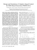
Formfactor’s Microsprings shown in Figure 1.2 successfully address problems of testing
many chips in parallel [5], which was not previously achievable by using epoxy or
membrane probe cards. It offers significant advantages over the other technologies,
which results in low cost and high performance with a 175 µm pitch wafer probing
solutions. A simple comparison among these available probing technologies is presented
in Table 1.1.
3
Figure 1.2: Formfactor’s Microsprings contacts
Technology Pitch
Cantilever
L
Coaxial
M
MEMS
L
Frequency
L
H
H
Pins
M
L
M
L-low
M-moderate
H-high
pitch
< 100 µm 100 – 1000 µm > 1000 µm
frequency < 2 GHz
2 – 5 GHz
> 5 GHz
pin count 100 - 500
500 - 1000
> 1000
Table 1.1: Comparison of different probing technologies
In this research work, the two interposers presented have vertical through wafer and
substrate interconnection and are capable of probing area array pins. They are thus
applicable to very fine pitch and high frequency tests. Fine pitch wafer level packages are
area array packages with extremely high pin density of 10000 pins/cm2. They are targeted
at high-end applications with electrical performance in the range of 5 to 10 GHz. The
Wafer Level Packages (WLP) interconnects test is critical due to its mechanical and
electrical constraints.
The motivation for developing an interposer to fit the purpose of high pin count and
density wafer level test is to reduce the cost for testing. If this interposer is successfully
4
designed and implemented, it can fulfill the task of a wafer level test, replacing BI
sockets, test sockets, handlers and trays with full wafer handling. Its compatibility with
the traditional Printed Circuit Board (PCB) processing technology will lead to reduced
spending on equipment, floor space, labor and other costs as well.
Another driving force behind this research work is that presently, using existing fine pitch
probes, testing at wafer level has strict limitations on number of I/Os that can be tested
concurrently. They are not good enough when the test structure is as small as 100um
pitch and when the number of I/Os is large and the operating frequency is 5 GHz and
beyond. For one of our target test specimens, the test chip of size 20 by 20 mm has 2256
I/Os, depopulated with 3 external rows – pitch 100 µm with three types of interconnects –
bed of nails, stretched solder columns or solder balls as shown in Figure 1.3.
Figure 1.3: Interconnects for wafer level packaged device
The WLP testing involves three major components. First is the electronic circuits that
create and detect the high frequency at which the device operates. Second is an interface
which links the test circuit hardware to the device under test, which is the interposer.
Thirdly we need a manual or an automated mechanism to align the leads of the WLP
device under test and the test interposer. Figure 1.4 shows the concept of this kind of
WLP test setup.
5
In te rp o s e r
P ow er
& USB
TSP
PCB
W a fe r
W a fe r C h u c k
uBG A
S ilic o n o r L T C C
o r P C B -lik e
T h in F ilm
R e d is trib u tio n
C o m p lia n t
C a p tu re /A lig n m e n t
S tru c tu re
Figure 1.4: WLP test concept
The signal is generated by multiplexing a low frequency clock from an external RF
source in a Programmable Gate Array (PGA) chip, designated as Test Support Processor
(TSP). It is possible to concurrently perform high speed, fine pitch probing over large pin
counts because many TSPs can be placed very close together. By keeping the signal
source close to the probe, signal integrity can be preserved. The clock signal is input
through the SMA connector. All test control signals are transmitted through the multi-pin
connectors to the probe card where multiple TSPs are mounted. The USB and power
connector are mounted on the probe card as well. The support logic chips surrounding the
TSP will handle the clock distribution, timing generation, data multiplexing and
driver/receiver buffering.
The interposer is the main focus of this research work. Having understood the mechanical
and electrical constraints that the desired interposer will have, a careful design must be
chosen for optimal high speed WLP test performance.
6
1.2 Project Objectives
The objectives of this research work are to design and characterize feasible interposers
meeting the requirements for the application of specific high speed test of the fine pitch
wafer level packaged devices with the target of preserving the signal integrity along the
transmission path. Subsequently, it is to implement the optimal design of the interposer
hardware and integrate it in the WLP test active circuits in order to establish
measurements results and demonstrate functional test performance. The measurement
results will serve as a good comparison to the simulations results as well.
The test specifications are as follows:
•
Insertion Loss: 1-2 dB at 5 GHz
•
High Speed I/O: 5 GHz
•
High I/O Density: about 1000-10000 pins/cm2
•
Pitch: 100 µm
•
Die Size: 20 mm x 20 mm
•
Compliance (Vertical Displacement): 5 µm
•
Max Temperature: 200 °C
1.3 Outline of Concept
In order to meet the specifications of the test as shown above, geometrical designs of the
interposers were done by carefully considering the limitations of available processing
technologies. Balancing between cost and effort required by selection of materials were
important as well. It often involved a lot of trade-offs between mechanical and electrical
7
performance. However, meeting the requirements of being capable of probing area array
pins and accommodating the DUT were the main concern. Another issue that needed to
be addressed in the specifications was the compliancy. For probing area array pins
simultaneously, it is important to have a mechanism to provide compliancy between the
leads and interconnects of the wafer level packaged device. Therefore, in the two
proposed designs, the compliant alignment issue was inherently taken into the
consideration when designing the geometries.
Electrical modeling and characterization of the geometries were subsequently performed
with the aid of commercial Computer Aided Design (CAD) software. Changes were often
made during the simulations to achieve the best electrical performance. The repeated
process of re-designing the geometrical properties of the interposer after a
characterization exercise was essential to achieving optimal electrical performance. This
process was the core research of this work with a lot of signal integrity issues needed to
be addressed.
The simulations were done in an Electromagnetic (EM) full-wave solver, Ansoft’s High
Frequency Structure Simulator (HFSS), implementing Finite Element Method (FEM).
The solver is capable of accurately predicting the high frequencies behavior of the 3D
models. It has the capability of taking into account of all real-world effects that would
have impact on the examined model under conditions prescribed by the user. Reliable
simulations results could only be achieved with important information given or specified.
8
The optimal design was fabricated and underwent a functional test. Measurements results
were obtained by using suitable instrumentations and tools. Comparisons between
simulations and measurements were made to identify discrepancies in the frequency
responses.
1.4 Thesis Layout
The layout of the thesis is as follows:
Chapter 2: A literature search was done to provide an overview of the probe cards
technology and techniques. Some popular probing techniques are reviewed. A literature
review on the signal integrity issue was also made. Signal integrity problems arising from
transmission lines are studied.
Chapter 3: Design and characterization of the proposed MEMS based interposer using
silicon as the substrate was done with modeling and simulation in order to optimize the
design. Simulations results are analyzed and discussed at the end of the chapter.
Chapter 4: Design, fabrication and characterization of the proposed elastomer based
interposer are presented together with detailed methodology on modeling. Simulation
results and discussions are also included, followed by measurement results and a
comparison to simulations results. Parametric variation study of the interposer is
performed for the rest of the chapter.
Chapter 5: The limitations of the proposed interposer designs are discussed. Suggestions
for possible improvements and future work conclude the thesis.
1.5 Original Contributions
In this project, the following original contributions have been made:
9
(i)
A MEMS based interposer using silicon as the substrate for high speed fine pitch
wafer level packaged devices test was designed. Electrical performance of the
interposer was fully characterized. Detailed methodologies of modeling and
optimization of signal integrity are presented together with simulations data.
Guidelines on future developments of this proposed are also given.
(ii)
An elastomer-based interposer for high-speed fine-pitch wafer-level packaged
devices testing was designed and fabricated, and its high frequency response was
successfully characterized. Modeling and optimization methods were examined
and are presented. The fabricated interposer was functionally tested and
measurements and simulations results are in good agreement. Future integration
with test processors or full wafer testing can be achieved with provided results
and insights.
Along the course of this research work, the following papers have been generated:
•
Jimmy P.H. Tan, J. Jayabalan, M. Rotaru, M.K. Iyer, B.L. Ooi and M.S. Leong, “Test
Bench Modeling and Characterization for Fine Pitch Wafer Level Packaged
Devices,” Electronics Packaging Technology Conference Proceedings, pp.502-505,
December 2004.
•
Jimmy P.H. Tan, C. Deng, S. Ang, H.H. Feng, A.A.O. Tay, M. Rotaru and D. Keezer,
“A MEMS Based Interposer for Nano Wafer Level Packaging Test,” Electronics
Packaging Technology Conference Proceedings, pp.405-409, December 2003.
10
Chapter 2
Literature Review
2.1 Probe Cards Technology
Semiconductors go through many testing processes during their production. One such
process is the testing of circuits in chips, which is an extremely important process for
ensuring the product performance and quality. This process also makes up a large portion
of production cost. Because of losses resulting from packaging faulty circuits,
semiconductor circuits are preferably tested while they are in the form of wafers. For
testing the circuits, an inspection tool called a ‘probe card’ is used. A probe card has
many needles (contact probes) that come into contact with electrodes in a chip. Figure 2.1
shows the basic composition of a semiconductor testing system.
11