Design and control of a teleoperation system for humanoid walking
Bạn đang xem bản rút gọn của tài liệu. Xem và tải ngay bản đầy đủ của tài liệu tại đây (2.75 MB, 93 trang )
DESIGN AND CONTROL OF A TELEOPERATION SYSTEM FOR
HUMANOID WALKING
SIM WAI YONG
(B.Eng(Hons.), The University of Adelaide.)
A DISSERTATION SUBMITTED FOR
THE DEGREE OF MASTER OF ENGINEERING
DEPARTMENT OF MECHANICAL ENGINEERING
NATIONAL UNIVERSITY OF SINGAPORE
2005
Acknowledgements
First of all, I would like to thank my parents. I would not be able to complete this
journey without them by my side.
I also like to thank my supervisors, Dr. Chew Chee Meng and Dr. Hong Geok
Soon, for their advice and guidance during my stay in the legged locomotion group.
What I have learned from them during these two years not only limited to academic
and technical aspects, but also helps me to be a better grown-up.
Special thanks to my labmates - Zhouwei, Sateesh, Fengkai, Samuel and Kuang Chin.
Not only for their support and valuable opinions, but also for their wonderful laughters
and crazy ideas.
Thanks to all the staff members of the Control and Mechatronics Lab - Ms Ooi, Ms
Shin, Ms Hamida, Mr Zhang, and Mr Yee. I could not have asked for more, they are
simply amazing.
ii
Table of contents
Acknowledgements
ii
Summary
v
1 Introduction
1.1 Organisation of Thesis . . . . . . . . . . . . . . . . . . . . . . . . . . . .
1
4
2 Background and Relevant Work
2.1 Bipedal Walking Control . . . . . . . . . . . . . . . . . . . . .
2.2 Teleoperation Overview . . . . . . . . . . . . . . . . . . . . .
2.2.1 Categories of Teleoperation System . . . . . . . . . . .
2.2.1.1 Teleoperation with Mechanical Transmission
2.2.1.2 Teleoperation with Electrical Transmission .
2.2.1.3 Computerized Teleoperation . . . . . . . . .
2.2.2 Motion Control Methods . . . . . . . . . . . . . . . .
2.2.2.1 Joint Space Control . . . . . . . . . . . . . .
2.2.2.2 Cartesian Space Control . . . . . . . . . . . .
2.2.2.3 Supervisory and Traded Control . . . . . . .
2.3 Applications of Teleoperation on Humanoid Walking . . . . .
.
.
.
.
.
.
.
.
.
.
.
6
6
10
10
11
12
12
13
13
14
14
15
.
.
.
.
.
.
.
.
.
.
17
17
19
19
21
22
27
29
29
29
31
4 Kinematic Study
4.1 Static Anthropomorphic Measurement . . . . . . . . . . . . . . . . . . .
4.2 Joint Range . . . . . . . . . . . . . . . . . . . . . . . . . . . . . . . . . .
32
32
33
3 Hardware Configuration of the Teleoperation System
3.1 Overview . . . . . . . . . . . . . . . . . . . . . . . . . .
3.2 Design of the Master Exoskeleton . . . . . . . . . . . . .
3.2.1 Design Concept . . . . . . . . . . . . . . . . . . .
3.2.2 First Prototype of Master Exoskeleton . . . . . .
3.2.2.1 Components of Exoskeleton . . . . . . .
3.3 PC and Decoder Unit . . . . . . . . . . . . . . . . . . .
3.4 Slave (Fujitsu Humanoid Robot HOAP-1) . . . . . . . .
3.5 Optional Components . . . . . . . . . . . . . . . . . . .
3.5.1 Head Mounted Display . . . . . . . . . . . . . . .
3.5.2 LED Indicator and Audio Speaker . . . . . . . .
.
.
.
.
.
.
.
.
.
.
.
.
.
.
.
.
.
.
.
.
.
.
.
.
.
.
.
.
.
.
.
.
.
.
.
.
.
.
.
.
.
.
.
.
.
.
.
.
.
.
.
.
.
.
.
.
.
.
.
.
.
.
.
.
.
.
.
.
.
.
.
.
.
.
.
.
.
.
.
.
.
.
.
.
.
.
.
.
.
.
.
.
.
.
.
.
.
.
.
.
.
.
.
.
.
.
.
.
.
.
.
.
.
.
.
.
.
.
.
.
.
.
.
.
.
.
.
.
.
.
.
.
.
.
.
iii
5 Control Methods and Dimensional Parameter
5.1 Direct Mapping of Joints . . . . . . . . . . . .
5.2 Mapping of Foot Positions . . . . . . . . . . . .
5.2.1 Forward Kinematics and Jacobian . . .
5.2.2 Inverse Kinematics Transformation . . .
5.3 Dimensional Parameter Study . . . . . . . . . .
6 Simulation
6.1 Mechanical Model and Control Method
6.2 Joint Trajectory Acquisition . . . . . . .
6.3 Ankle Joint Data Modification . . . . .
6.4 Final Joint Trajectories . . . . . . . . .
6.5 Model of the Ground . . . . . . . . . . .
6.6 Results of Geometric Scaling . . . . . .
6.6.1 Continuous Walking . . . . . . .
6.6.2 Landing Impact . . . . . . . . . .
6.7 Result of Froude Number Scaling . . . .
6.7.1 Body Pitch . . . . . . . . . . . .
6.7.2 Zero Moment Point . . . . . . .
6.7.3 Gait Phases . . . . . . . . . . . .
6.8 Discussion of Simulation Results . . . .
.
.
.
.
.
.
.
.
.
.
.
.
.
.
.
.
.
.
.
.
.
.
.
.
.
.
.
.
.
.
.
.
.
.
.
.
.
.
.
.
.
.
.
.
.
.
.
.
.
.
.
.
Study
. . . .
. . . .
. . . .
. . . .
. . . .
.
.
.
.
.
.
.
.
.
.
.
.
.
.
.
.
.
.
.
.
.
.
.
.
.
.
.
.
.
.
.
.
.
.
.
.
.
.
.
.
.
.
.
.
.
.
.
.
.
.
.
.
.
.
.
.
.
.
.
.
.
.
.
.
.
.
.
.
.
.
7 Experimental Results
7.1 Experiment 1 - Stepping . . . . . . . . . . . . . . . . . .
7.2 Experiment 2 - Direct Mapping of Joints . . . . . . . . .
7.3 Experiment 3 - Mapping of the Foot Position . . . . . .
7.4 Experiment 4 - Modification of Playback Time Interval .
7.5 Experiment 5 - Modification of Walking Profile . . . . .
.
.
.
.
.
.
.
.
.
.
.
.
.
.
.
.
.
.
.
.
.
.
.
.
.
.
.
.
.
.
.
.
.
.
.
.
.
.
.
.
.
.
.
.
.
.
.
.
.
.
.
.
.
.
.
.
.
.
.
.
.
.
.
.
.
.
.
.
.
.
.
.
.
.
.
.
.
.
.
.
.
.
.
.
.
.
.
.
.
.
.
.
.
.
.
.
.
.
.
.
.
.
.
.
.
.
.
.
.
.
.
.
.
.
.
.
.
.
.
.
.
.
.
.
.
.
.
.
.
.
.
.
.
.
.
.
.
.
.
.
.
.
.
.
.
.
.
.
.
.
.
.
.
.
.
.
.
.
.
.
.
.
.
.
.
.
.
.
.
.
.
.
.
.
.
.
.
.
.
.
.
.
.
.
.
.
.
.
.
35
35
36
37
40
41
.
.
.
.
.
.
.
.
.
.
.
.
.
44
44
46
47
47
50
50
50
52
52
53
55
56
57
.
.
.
.
.
60
60
64
66
71
73
8 Conclusion and Future Works
78
References
81
Appendices
83
A Mass Property of Fujitsu Humanoid Robot
84
iv
Summary
This thesis presents the design and control of a teleoperation system for humanoid. The
focus of this project is the teleoperation of the sagittal plane walking. The teleoperation
system consists of three major components - the master exoskeleton, PC and the slave
humanoid robot.
The motivation behind this research project is to explore the possibility of the novel
control method of teleoperation for humanoid walking. Two of the major factors that
limit the application of humanoid robot in uncontrolled working environment are the
lack of robustness in the current walking methods and lack of breakthrough in artificial
intelligence. Participation of human in the control loop is appealing as this takes away
the dependence of artificial intelligence.
The thesis describes the details of the mechincal design of the master exoskeleton, the
control architecture of the overall system, and the control methods. Simulation result of
direct mapping of human walking profile on humanoid robot is presented. Experimental
results that verify the hardware system and different control method are also presented.
v
List of Figures
2.1
A typical teleoperation configuration . . . . . . . . . . . . . . . . . . . .
3.1
Overall hardware configuration of the proposed teleoperation system. Major components in the master environment include master exoskeleton and
PC and decoder unit; optional components are the Head Mounted Display
(HMD), LED indicator and speaker. Fujitsu humanoid robot HOAP-1 is
chosen to be the slave robot. . . . . . . . . . . . . . . . . . . . . . . . .
Hardware setup of the proposed teleoperation system. . . . . . . . . . .
Left: Joint coordinates for the exoskeleton. Right: Human operator with
the exoskeleton. . . . . . . . . . . . . . . . . . . . . . . . . . . . . . . . .
Top: Important part names for waist unit. Bottom: Illustration of movable parts of waist unit, along with degree of freedom and coordinates of
waist unit. . . . . . . . . . . . . . . . . . . . . . . . . . . . . . . . . . . .
Top: Parts breakdown drawing for thigh/shank unit. Bottom: Illustration of the degree of freedom and coordinates of thigh/shank unit. Note
the jig which can be inserted into the alignment slot for the purpose of
initialization of the encoders. . . . . . . . . . . . . . . . . . . . . . . . .
Attachment points of the master exoskeleton. . . . . . . . . . . . . . . .
Schematic of the electronic circuit of the decoder unit. . . . . . . . . . .
Decoder circuit. . . . . . . . . . . . . . . . . . . . . . . . . . . . . . . . .
Top: Fujitsu HOAP-1 Humanoid Robot. Bottom: Joint coordinates of
HOAP-1. . . . . . . . . . . . . . . . . . . . . . . . . . . . . . . . . . . .
3.2
3.3
3.4
3.5
3.6
3.7
3.8
3.9
5.1
5.2
5.3
6.1
6.2
6.3
6.4
6.5
Control block diagram of the method direct mapping of joints . . . . . .
Control block diagram of the method mapping of foot positions . . . . .
Frame attachment diagram for master exoskeleton. Left: Stance leg.
Right: Swing leg. . . . . . . . . . . . . . . . . . . . . . . . . . . . . . . .
Mechanical model of Fujitsu humanoid robot HOAP-1. Left: Subscript
h, k and a represent hip, knee and ankle respectively, while R and L
represents right and left. Right: Body pitch angle. . . . . . . . . . . . .
Man walking at normal speed. Muybridge (1955) . . . . . . . . . . . . .
Top: Illustration of robot foot interfere with ground while playback the
trajectory directly. Bottom: Comparison between human foot and robot
foot. The ankle is the center of rotation. . . . . . . . . . . . . . . . . . .
Top: Joint trajectories for left foot. Bottom: Joint trajectories for right
foot. Blue, yellow and magenta represents hip, knee and ankle respectively.)
Snapshots for one gait cycle. Time interval is 0.083sec. . . . . . . . . . .
11
18
19
23
24
26
27
28
28
30
37
38
38
45
46
48
49
51
vi
6.6
Ground reaction force of swing foot after landing. Blue and red represents
data for heel and toe respectively. . . . . . . . . . . . . . . . . . . . . . .
6.7 Comparison of the body pitch profile between kinematic scaling method
and Froude number scaling method. The plot depicts the body pitch in
one gait cycle. . . . . . . . . . . . . . . . . . . . . . . . . . . . . . . . . .
6.8 ZMP profile of right foot during right stance phase of the gait cycle. This
profile is plotted against the time of right stance phase. The y-axis value
of 0 represents ZMP is located at the heel, whereas 0.098 represents toe.
6.9 ZMP profile of left foot during left stance phase of the gait cycle. This
profile is plotted against the time of left stance phase. The y-axis value
of 0 represents ZMP is located at the heel, whereas 0.098 represents toe.
6.10 Phase comparison between normal, foot regulated, and scaled simulations.
7.1
7.2
7.3
7.4
7.5
7.6
7.7
7.8
7.9
7.10
7.11
7.12
7.13
7.14
7.15
Snapshots of the stepping experiment. Snapshots are taken in the time
interval of 1 second. (From left to right, top row to bottom row) . . . .
Right leg joint trajectories. Blue: Hip; Magenta: Knee; Yellow: Ankle. .
Left leg joint trajectories. Blue: Hip; Magenta: Knee; Yellow: Ankle. . .
ZMP history for the stepping experiment. The red dash lines are the limit
for the ZMP value, which is maximum +43 and minimum -26. ZMP for
right and left foot are represented in yellow and turquoise lines respectively. The boxes at the bottom of the graph are the state of the humanoid
robot - bright green: right foot lifted; light green: left foot lifted; yellow:
double support. . . . . . . . . . . . . . . . . . . . . . . . . . . . . . . . .
Walking sequence of direct teleoperation. The humanoid robot shown
instability during landing of swing foot and eventually fall at the second
step. . . . . . . . . . . . . . . . . . . . . . . . . . . . . . . . . . . . . . .
Illustration of the difference in timing for the landing of the swing foot.
Arrow-a: Human operator has landed his swing foot. Arrow b: Left leg
of the humanoid robot is yet to land. . . . . . . . . . . . . . . . . . . . .
Walking sequence of teleoperation by mapping of the foot position. . . .
Walking sequence of the humanoid. Notice the first snapshot, the knee of
the humanoid robot is bent even human operator is stand with straighten
knee. This is a measure to prevent singularities in the Inverse Kinematic
algorithm. . . . . . . . . . . . . . . . . . . . . . . . . . . . . . . . . . . .
Comparison of the knee configuration of Direct joint mapping method
and Foot mapping method. . . . . . . . . . . . . . . . . . . . . . . . . .
Leg joint trajectories for experiment 3. . . . . . . . . . . . . . . . . . . .
Foot trajectories for experiment 3. . . . . . . . . . . . . . . . . . . . . .
Snapshots of the experiment of scaling based on modification of playback
time interval. . . . . . . . . . . . . . . . . . . . . . . . . . . . . . . . . .
Snapshots of the experiment of scaling based on modification of walking
profiles. Notice the small stride length and step height of the robot. . .
Leg joint trajectories for experiment 5. Blue: Hip; Magenta: Knee; Yellow: Ankle. Notice the scaling down of the joint angles of the slave
compare with the master. . . . . . . . . . . . . . . . . . . . . . . . . . .
Foot trajectories for experiment 5. Blue: Vertical foot position; Yellow:
Horizontal foot position. Notice the scaling down of the foot position of
the slave compare with the master. . . . . . . . . . . . . . . . . . . . .
53
54
55
56
57
61
62
63
63
65
65
67
68
68
69
70
72
74
75
76
vii
List of Tables
3.1
Specification of US-Digital E3 Encoder . . . . . . . . . . . . . . . . . . .
21
4.1
4.2
Link length comparison between human and Fujitsu humanoid robot . .
Joint range comparison between human and Fujitsu humanoid robot . .
34
34
6.1
Comparison of body pitch profile between geometric scaling method and
Froude number scaling . . . . . . . . . . . . . . . . . . . . . . . . . . . .
54
A.1 Mass Property of Fujitsu Humanoid Robot . . . . . . . . . . . . . . . .
85
viii
Chapter 1
Introduction
Robot holds the advantage of being less susceptible to hazardous working environment
over human. As wheeled robot has less maneuverability in rough terrain and unstructured environment, it is foreseeable that legged robot, especially, the humanoid robot
will be an important workforce in harsh and extreme working conditions, for example,
the presence of intense heat and smoke in fire disaster area, or radiation in the nuclear
plant, etc. Taking advantage of the advancement in bipedal walking control, several humanoid robots, namely the Honda Asimo (Hirai, 1998) and Sony Qrio (Kuroki, 2003),
have recently showcased the capability of walking not only on flat surface, but also on
terrain of limited unevenness. However, their adaptability to natural environment is
somehow still rather limited.
The use of a fully autonomous humanoid robot, which should not only be able to
complete the task given, but also perceived and react in accordance to the unstructured
environment, is unlikely to be realized in the near future. For a robot to be able to
function independently and complete the tasks in a highly varied environment, the crucial element is a well developed and competent artificial intelligence. Unfortunately, the
research and development of artificial intelligence is yet to keep pace with the progress
of hardware technology.
A typical example to illustrate the complexities and difficulties of utilizing a autonomous robot in real environment is the task of approach, identify and capture. The
1
scenario can be very simple, at least for humans - to walk across an office layout with
cubicles and pick up a cup from the table. To accomplish the task, the robot has to
know where it is at, where the destination is, which path to take, which cup to take,
and how to take it. The process for these tasks can be divided into two categories - low
level process and high level process.
Low level processes include localization, image processing, sensor data acquisition
and fusion, and local control of the actuators. The task of localization and image processing is somewhat related closely, as the former rely on the output of latter. Localization
involve two basic subtasks - mapping of the surroundings and depth map generation.
Image processing is vital such that information about the surroundings and robot itself
is acquired accurately. Hence an advanced and effective image processing algorithm is
required, such that the effect of variables, such as lighting conditions, can be minimized.
In contrast to the state of sensor technology, the process of sensor data fusion is still
elementary. Sensor data fusion is the combination of redundant sensor information into
a useful and accurate one. It is obvious that to be able to process the above three tasks,
high computing power is required onboard for autonomous robot. The control of the
actuators is the least problematic task of the four. High accuracy tracking of the trajectory of DC motors, the most commonly used actuator in robot, is achievable nowadays
thanks to the advanced and continuous research of the controller.
High level process involve strategic and decision making. One of typical tasks is the
process of path generation - how to get to the destination. Path generation is an online
process. Basically, the robot needs to know which way to go and how to get there. This
usually consists of choosing different motion patterns according to situations, which
require a huge bank of motion patterns. Obviously a powerful artificial intelligence is
needed in order to deal with the entire unknown situations in the unstructured environment. Such a well-developed artificial intelligence is not yet available at the moment,
and it is difficult to say when this area will have a break through such that artificial
intelligence can be at least comparable to an infant.
From the example elaborated above, it is expected that a partial autonomy in the robot system would be a solution that will overcome the current limitation and difficulties
2
of robot deployment in the real working environment. The allocation of the tasks in this
partial-autonomous system should take into account of the strengths, capabilities and
limitations of the humans and robots. Humans in general are good at perceptions and
understanding, task decomposition, problem solving and replanning of fault recovery,
while robots are better at low level sensory and control functions, trajectory planning,
precision motion, performing routine and repetitive tasks. By combining the strengths
of two parties, the replacement of robots in the hazardous working environment can be
realized soon.
The participation of human in the control loop of a robot system is not a new idea,
however most of the research is done on robot manipulators with a fixed base. The
application of teleoperation on humanoid walking is relatively rare; consider only two
cases so far in the world - Honda robot (Hirai, 1998) and HRP-1S (Kaneko, 2002). Nevertheless, due to the supervisory control nature (Hannaford, 2000) of the teleoperation
system applied on those two cases, the robots are still not able to adapt to the highly
unstructured environment. Some of the limitations include the following:
1. Landmarks for environments are needed for visual processing.
2. Staircase parameters such as height, width and numbers of steps need to be known.
3. Relatively complex system as the supervisory control involve only high level commands, low level processing such as visual processing, motion generation are still
a burden of the robot.
4. A huge motion data bank is needed to adapt to the unstructured environment.
A novel approach to extend the walking capability of humanoid robot by means of
teleoperation (Sim et al., 2004) has been introduced. The novelty of the proposed system
is the difference of the control method with other research works. Instead of passing the
high level command to the robot through the computer console and let the humanoid
to generate walking motion itself, the proposed system actually make the control of the
humanoid walking more intuitive. By wearing the exoskeleton type master interface,
the leg motion of the human operator can be either directly map to the humanoid, or
3
the human can control the foot placement of the humanoid during locomotion. This
way, the human operator is able to control the humanoid as if he himself is the robot,
and at the same time the humanoid robot has the advantage of better adaptability to
unstructured environment.
This thesis describes the details of the design and control of the teleoperation system for humanoid walking. The design process of the master exoskeleon, the control
architecture and the electronics implementations are discussed. Dimensional analysis is
also included in this thesis to investigate the applicability of different scaling methods.
The simulation result and experimental result are also presented in this thesis.
1.1
Organisation of Thesis
The thesis proceeds as follows:
Chapter 2 gives the background study for this thesis. Various control approaches
for humanoid walking and their limitations are discussed, followed by an overview of
teleoperation and its application.
Chapter 3 presents the hardware configuration of the teleoperation system. Design
of the master exoskeleton will be discussed in detail. The selection of encoders, technical
specifications of the design and the design strategy are explained.
Chapter 4 presents the kinematic study of human and humanoid robot. A comparison between human and humanoid robot will be discussed. Feasibility of the proposed
teleoperation system will be proven.
Chapter 5 introduces the control method of the teleoperation system. Dimensional
analysis will also be included in this chapter.
Chapter 6 gives the details of the simulation result of the two scaling methods. This
chapter will include the details of the simulation approaches and analysis of the result.
Chapter 7 presents the experimental results of the teleoperation system. Five experiments has been conducted to test the system, namely the hardware evaluation test,
experiment of direct mapping of joints, experiment of mapping foot positions, and ex-
4
periment on two different scaling methods.
Chapter 9 concludes the thesis with a discussion and advice on future research.
5
Chapter 2
Background and Relevant Work
In this chapter, some background and relevant work will be presented. Section 2.1
presents the various control methods that researchers adopt for bipedal walking. Section 2.2 is an overview of teleoperation and classifications of the control methods of
teleoperation system.
2.1
Bipedal Walking Control
Achieve stable walking for humanoid robot is a difficult task. Some of the major issues associated with control of bipedal locomotion are listed as followed (Vukobratovic,
2004):1. Bipedal systems are high-order highly-coupled nonlinear dynamical systems.
2. The discrete changes in the dynamic phenomena. The locomotion mechanism
changes from open to a closed kinematic chain during a single walking cycle.
3. The underactuated degree of freedom between the support foot sole and the ground
cannot be controlled directly.
4. The uncertainty of the walking surface and environment.
5. The capability of the mechanical implementation due to the limitation of the
actuators, which included consideration of the size, power to weight ratio etc.
6
From the point of view of the center of gravity, bipedal locomotion can be divided into
two categories - static walking and dynamic walking. In static walking, the projection
of the center of gravity on the ground is always kept within the support foot area. As
this kind of locomotion is named - the dynamic effect is negligible, which means that
the humanoid robot has to move in a relatively slow motion. Another characteristic of
such kind of locomotion is that at anytime the humanoid robot stop its motion, it will
remain in the stable position indefinitely.
Dynamic walking is much complicated in terms of control, maintenance of balance
and also the generation of a valid walking pattern. Nevertheless, dynamic walking is a
better approach due to the fact that dynamic walking provides faster walking speed and
greater efficiency than static walking. For this reason, studies on dynamic walking has
been the focus of researchers worldwide. The walking control method can be classified
into five groups - model based, ZMP (Zero Moment Point) based, biological inspired,
learning, and divide-and-conquer.
Model-Based Method The principle of model-based method of biped walking control is straight-forward - by applying law of physics, a mathematical model of the biped
robot is derived and to be utilized in the synthesis of control algorithm. The most
notable example of this category is the Linear Inverted Pendulum model proposed by
S. Kajita (Kajitha et al., 1991). It is considered the simplest model that describe the
bipedal locomotion. The model of Linear Inverted Pendulum describe the motion of the
center of mass (COM) of a planar biped with mass-less legs. During single support of
the walking cycle, the motion of the COM behaves like a point mass inverted pendulum
with variable length. The dynamic equations of the linear motion of the COM can be
solved analytically. The trajectory of the joints of the biped robot can be found by
using inverse kinematics and tracked by simple position control. Ankle torque is used
to compensate for any disturbance or errors in the model. This simple control method
has been realized in the real robot Meltran.
Advantage of this method is its simplicity and the analytical closed-form solution.
However, this method is limited to situation which the ground profile is known and well-
7
defined, as the constraint line of motion of the COM of the model is defined with respect
to the ground. Another pitfall of this method is the consideration of the dynamic effect
of the swing leg as a disturbance, which is compensated by the ankle torque. As the
ankle torque of the biped robot is limited due to underactuation nature of the support
foot sole and the ground, the effectiveness of such disturbance-compensation would be
hindered.
The Linear inverted Pendulum model has been extended to 3-D recently (Kajitha,
2002). The control method has been utilized in the robot Meltran II to prove its applicability.
ZMP Based Method The concept of Zero Moment Point (ZMP) has gained wide
acceptance since it was introduced in 1973 (Vukobratovic, 1973). ZMP has been playing
a crucial role in solving the biped robot stability and dynamic walking pattern synthesis.
Zero Moment Point is defined as the point on the ground in which the sum of all moments
of the active torques equals to zero. If the ZMP is within the convex hull of all contact
points between the foot and the ground (support polygon), the robot will walk in a
dynamically balance fashion.
This method can be used in two ways - walking pattern synthesis and verification
of a walking pattern’s stability. By means of walking pattern synthesis, researchers
preplanned ZMP profile such that it is within the support polygon at all time during
the walking cycle, the trajectory of COM of the biped robot is then calculated. Similar
to the case of Linear Inverted Pendulum method, once the trajectory of COM of the
biped robot is obtained, the trajectory of all the joints of the biped robot can be found
by using inverse kinematics.
In the second approach, the ZMP criteria is served in later part of an offline joint
trajectories planning as a verification of stability. The offline trajectory planning is one
of the most elementary method to control a biped walking. Among them, the simplest
and most intuitive way of obtaining the joint trajectories is to record the human motion
and post-process the data such that it satisfy the ZMP criteria in simulation before
implementing in the real robot. It is expected that this method requires much effort in
8
tuning as the trajectory which works in simulation might not work in real robot. This
method has been used in the development stage of the Honda robot.
Biological Inspired Method Biological inspired method is based on the belief of
the possibility of extracting information from biological system - living life, that can be
implemented on artificial system. One of the most extensively used approaches is the
Central pattern generation (CPG).
Evidences have been widely accepted as a support to the hypothesis that there exists
neural networks in the spinal cord of animals (also humans), referred to as ”central
pattern generators” (CPGs), that are capable of producing rhythmic movements, such
as swimming, walking, and hopping. Several researches have been conducted in order
to extract this piece of information and implement in biped robots (Zielinska, 1996;
Taga, 1995; Jalics at al., 1997). The generation of the periodic signals - reference joint
trajectories, is created by using a coupled Van der Pol nonlinear oscillator equations. If
the signals are generated in an appropriate way, the biped is able to walk stably.
Learning Method Learning method has been used in systems that is complex and
difficult to model. It is hardly surprising that researchers have been playing with the
idea of implementing learning method on bipedal walking. Neural Networks and Reinforcement Learning are the two popular learning tools that researchers used. Successful
example of implementation of Neural Networks in bipedal walking include Miller, Reil
and Hu. Reinforcement learning was extensively used in the research of Chew and Pratt
(Chew et al., 2002), and Benbrahim and Franklin.
Divide-and-conquer Method Divide-and-conquer method is the practice of breaking a complex problem into small and simple problems. Bipedal walking is a complex
and difficult control problem. Generally speaking, 3-D bipedal walking can be divided
into frontal plane, transverse plane and sagittal plane walking; or even a smaller number
of subtasks. This approach has been illustrated by the research work of Raibert and
Pratt.
9
2.2
Teleoperation Overview
”Teleoperation” technology support a form of control in which the human directly guides
and causes each increment of motion of the slave (Hannaford, 2000). Typically the slave
robot follows the human motion exactly. However in some more advanced and computer
mediated system, there may be coordinate transformation imposed between the master
and slave. A teleoperation system generally sends one of the conjugate variables (either
force or velocity) from the operator side to the slave. If the conjugate variable is sent
back from the slave and transferred to the operator, a virtual energetic link can be
created.
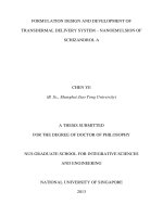
In general, three environments exist for teleoperation system: master environment,
slave environment and X environment (Vertut, 1985). The master environment houses
the human operator and the control system. The role of the human operator can be
divided into action, sensing and decision making. The control system can be anything
ranging from some special mechanical structure, or even a pointing device, to a computer
console. The slave environment corresponds to the work area of the slave, which is
located some distance away, or separated by some physical barrier from the master
environment. The X-environment, generally refer to the content of a certain task to
be accomplished in the slave environment. It is situated in human operator’s mind in
reality. A general configuration of teleoperation is depicted in Figure 2.1.
2.2.1
Categories of Teleoperation System
Teleoperation systems can be divided into three categories based on their functional
complexity and channels of data transmission. The three categories are teleoperation
with mechanical transmission, teleoperation with electrical transmission and computerized teleoperation (Vertut, 1985).
What is common in these three categories of teleoperation system is the role of the
human operator. The role of the human operator can be divided into three groups
internally - mechanical actions, sensing abilities and decision making abilities. The
properties of these categories are described as below:-
10
Control system
Slave
Remote
data
action
Sensing
Action
Slave environment
Decision
making
Human operator
Task to run
Master environment
X environment
decision making and action
data
Figure 2.1: A typical teleoperation configuration
1. Sensing - receives data from the external environment (both master and slave) and
transmits to the brain.
2. Decision making - based on the data from sensing operator and the knowledge of
the task and make necessary decision.
3. Mechanical action - taking the command of the decision making operator and
generation of physical actions to be realized in the real world.
2.2.1.1
Teleoperation with Mechanical Transmission
This is the most elementary teleoperation system. The earliest teleoperation system
is realized in this mode. In this type of teleoperation system, a mechanical link is
constructed between the master environment and slave environment. Usually the master
and slave is separated by a shielding which allows the human operator to view the slave
environment through a transparent window. This type of system involves little or none
of the electronics as the movements are transmitted mechanically. Typical application
11
is the handling of radioactive or biohazard materials in research lab.
2.2.1.2
Teleoperation with Electrical Transmission
In this type of teleoperation system, the mechanical link between the master and the
slave is replaced by an electrical link. In this mode, the distance between the master and
the slave is now increased significantly. However, some undesirable side effects occur due
to the increase of this physical space separation. Some of the major drawbacks include
the loss of direct vision feedback, the loss of direct force feedback and the effect of time
delay.
Solutions to these drawbacks have been resolved, to certain degree by some of the
researchers. Partial vision feedback from the slave environment is able to restore by
using cameras. Force feedback can be regenerated by artificial synthesis force based on
the measurement of torques/force experienced in slave. However, performance of the
teleoperation is generally reduced as these substitution is just limited replication of the
the direct feedback.
2.2.1.3
Computerized Teleoperation
One way to solve the problems of teleoperation by electrical transmission is to introduce
a computer in between the master and slave as a second operator. This second operator
has limited capability as of human - limited ability of sensing and decision making. The
second operator will, ideally, facilitate the teleoperation by assisting in the appropriate
decision making and action. However this will increase the complexity of the system
and required careful and complicated design.
Other than the introduction of this second operator, the more recent development of
the computerized teleoperation is the introduction of virtual environment. By replicate
the slave environment using computer graphics, researches shown a significant improvement of teleoperation using this kind of virtual graphic feedback.
12
2.2.2
Motion Control Methods
Other than the direct transmission of motion of teleoperation system with mechanical
transmission, there are three types of motion control method. Joint space control basically is limited to those systems in which the kinematic similarity between master and
slave is apparent. Cartesian coordinate control is usually used where the orientation of
the end-effector of the slave is not critical. These two control method is used in the
teleoperation system with electrical transmission. The last category of motion control
method is the computerized teleoperation. Computer is added into the control loop to
assist human operator.
2.2.2.1
Joint Space Control
In some teleoperation systems, the motions of the human operator must be continuously
reproduced by the slave robot. Normally, the master and slave arms are kinematically
(geometrically) identical within a scale constant. In this case it is adequate to transmit
the angles of the individual joints of the master robot arm. Because of the kinematic
similarity, the motion of the slave’s end effector will exactly follow that of the master if
the slave’s joints follow the same trajectory as the master’s joints. Both the master and
slave side motion can therefore be represented in joint coordinates.
A special case of communication arises when the joint coordinates transmitted from
the master side are those of the human arm itself - exoskeletons. The human operator
wears an exoskeleton - actually a robotic mechanism into which the human’s arm can
fit, and the joints of the exoskeleton are aligned with the human joints. The slave robot
must then have the same kinematic equations as the human arm. One advantage of this
approach is that it is relatively easy to design an exoskeleton that can track the entire
workspace of the human arm. Apart from the difficulty of wearing the exoskeleton,
initialization of the system is also a problem. Initialization is critical for this type of
control method as any offset during the initialization of the exoskeleton will seriously
jeopardize the performance of the teleoperation.
13
2.2.2.2
Cartesian Space Control
Joint coordinates control might not be feasible for some application, such as when the
master device have to be operated in a confined space. In this case, it is essential that
the master and the slave can be kinematically different. Instead of controlling every
joints of the slave, the master control only control the end-effector’s cartesian position.
Joystick is the most commonly used master device for this type of teleoperation. The
teleoperation systems developed in which the master and slave have different kinematic
designs are sometime called generalized teleoperation system.
2.2.2.3
Supervisory and Traded Control
The third kind of control method is developed for the purpose of eliminating the problems associated with joint coordinates. For telerobots, only goals are communicated,
so that this requirement is relaxed. Sheridan used the term ”Supervisory Control” to
denote a type of control in which goals and high level commands are communicated to
the slave.
Although supervisory control in principle avoids the need for a pointing interface,
such as a master manipulator or exoskeleton, one is sometimes included to overcome the
limited capability of the autonomous slave. Situation such as this is quite common as
some skills or procedure needed of an application cannot be performed by an autonomous
system at the slave site. It is expected when the environments are highly structured
and external perturbations and uncertainty are kept minimal; pointing devices are not
required. On the other hand, in order to have a high degree of confidence of task
completion in an uncertain environment, both teleoperation and supervisory modes are
needed. In practice, the control teleoperation systems are often switch between human
(teleoperator) and computer (telerobot). These systems can be termed ”traded control”
because low level control of the slave robot motion passes back and forth between human
operator and robot.
14
2.3
Applications of Teleoperation on Humanoid Walking
Despite the widely recognized benefits of teleoperation in uncertain environments, not
many researches have been done for the teleoperation of the humanoid walking. In fact,
only two notable publications are found. Both publications are from research institutes
which can be considered as leaders in the humanoid research in Japan.
The first one is reported by the researchers of Humanoid Robotics Project (HRP)
(Hasunuma, 2002) sponsored by the Ministry of Economy, Trade and Industry (METI)
of Japan. The main purpose of the paper is to describe the results of investigations and
experiments as for proxy drive of a forklift by humanoid robot HRP-1. The teleoperated
humanoid robot platform consists of a humanoid robot (HRP-1), and a remote control
cockpit system. The control of the bipedal walking is input directly using a display
screen with the 3D mouse as a command input device. The parameters for the bipedal
walking are the desired position x, y and orientation with relative to the current position
and orientation; and the high level command of walking up or down a number of steps of
the staircase. As this experiment is focused more on the task of teleoperated driving of
forklift, it is designed relatively simple for the walking. The humanoid is only required
to walk up a staircase to the driving position of the forklift. The experiment result
demonstrates the idea of using teleoperation in order to extend the limited capability of
humanoid in real application.
The second paper is the work by Hirai et al. (1998) for the Honda robot. The team
has constructed an integrated system for the Honda robot which can automatically
perform certain tasks in a known environment, and tasks in an unknown environment
with the assistance from a human operator. The integrated system consists of the
robot itself and its teleoperation console. The functional blocks of teleoperation console
consists of the user interface, action planner, environment map and dynamics control
module of the master arm. The operator inputs the basic locomotion path and action to
the user interface. The action planner modifies the basic plan by the vision processing
result and sends the basic action commands such as ”go straight”, ”turn”, ”go up stairs”,
and so forth. In the environment map, there are the information of the position and the
15
landmarks, the shape parameters of the stairs, etc. Using these function modules, the
robot is able to walk autonomously according to the locomotion path.
However, due to the supervisory control (Hannaford, 2000) nature of the teleoperation system applied on those two cases, the applications of robots are still limited to
structured environment. Some of the limitations include the following:
1. Landmarks for environments are needed for visual processing.
2. Staircase parameters such as height, width and number of steps need to be known.
3. Relatively complex system as the supervisory control involves only high level commands, low level processing such as visual processing, motion generation are still
a burden for the robot.
4. A huge motion bank is needed to adapt to the unstructured environment.
16
Chapter 3
Hardware Configuration of the
Teleoperation System
3.1
Overview
By using the general mechanical teleoperation framework (Vertut, 1985), a concept of
teleoperation system for humanoid robot has been constructed. The master environment
consists of two major components, which are the master interface and the head mounted
display. As for the slave environment, a HOAP-1 Fujitsu Humanoid is used as the slave.
A PC acts as the main controller interfacing between the master and slave.
The master interface is an exoskeleton type of mechanical linkage which attached to
the human operator. The function of the master interface is to capture the joint information in our teleoperation system. It is designed such that the linkage is kinematical
similar to the robot leg, with each joint equipped with an incremental encoder. The
major advantage of having such an interface is it makes the control of the robot leg easy
- straight forward mapping the angle to the slave, and the human operator can control
the robot leg intuitively.
The encoder data captured from the exoskeleton is then transfer to the PC before
sending to the slave in real-time, either by using a LAN or USB cable. The visual data
obtained through the robot’s camera will be displayed through the head mounted display
17