Development of an elastic path controller for collaborative robot
Bạn đang xem bản rút gọn của tài liệu. Xem và tải ngay bản đầy đủ của tài liệu tại đây (2.87 MB, 81 trang )
DEVELOPMENT OF AN ELASTIC PATH CONTROLLER FOR
COLLABORATIVE ROBOT
LONG BO
(B.Eng, Huazhong University of Science and Technology)
A THESIS SUBMITTED
FOR THE DEGREE OF MASTER OF ENGINEERING
NATIONAL UNIVERSITY OF SINGAPORE
SINGAPORE
2005
ii
Acknowledgements
I would like to thank Dr. Teo Chee leong and Dr. Etienne Burdet, my supervisors, for their
many valuable suggestions and constant support during this research.
Suggestions from Dr. Yu Haoyong made this work moving forward faster.
My friend and collaborator, Rebsamen Brice, who gave me a lot of nice suggestions on
the programming, and helped me to overcome my laziness and encouraged me to pursuit a
higher degree.
And many thanks to Dr. J.Edward Colgate and Dr. Michael Peshkin, their kindness and
warm heart made us possible to test the elastic path controller on the Scooter cobot in
Laboratory for Intelligent Mechanical Systems(LIMS). Eric Faulring gave me selfless help
during my stay at the LIMS.
I dedicate this thesis to my parents, you gave me love when I felt lost in the life. You are
the only reason why I gonna be better.
Without the help of the people mentioned above, this work would never have come into
existence.
Finally, I wish to thank the following: He Cong (for her encouragement, pressure and
porridge when I got sick); Hu Jiayi (for changing my life from worse to bad); Wang Fei,
Liu Zheng, Ganesh Gowrishankar, Ankur Dhanik (for all the good and bad times we had
together).
iii
Table of Contents
Acknowledgements
ii
Table of Contents
iii
Summary
v
1 Introduction
1
2 The
2.1
2.2
2.3
.
.
.
.
.
.
6
6
12
12
12
16
17
3 Elastic path controller
3.1 Design requirements . . . . . . . . . . . . . . . . . . . . . . . . . . . . . . .
3.2 Elastic Path Controller for the Collaborative Wheelchair . . . . . . . . . . .
3.3 Discussion . . . . . . . . . . . . . . . . . . . . . . . . . . . . . . . . . . . . .
19
19
20
23
4 The
4.1
4.2
4.3
4.4
.
.
.
.
26
26
27
28
29
for wheelchair Cobot
. . . . . . . . . . . . . . . . . . . . . . .
. . . . . . . . . . . . . . . . . . . . . . .
. . . . . . . . . . . . . . . . . . . . . . .
33
33
36
36
2.4
Collaborative Wheelchair Assistant
Research on Robotic Wheelchairs . . . . . . . . . . . . . . . . .
Definition of the Collaborative Wheelchair Assistant . . . . . .
Kinematics . . . . . . . . . . . . . . . . . . . . . . . . . . . . .
2.3.1 Kinematics model of a moving point . . . . . . . . . . .
2.3.2 Kinematics model of Collaborative Wheelchair Assistant
Path controller . . . . . . . . . . . . . . . . . . . . . . . . . . .
Scooter Cobot
Scooter . . . . . . . . . . . .
Kinematics . . . . . . . . . .
Derivation of control variable
Elastic path controller . . . .
.
.
.
.
.
.
.
.
.
.
.
.
5 Simulation on Elastic Path Planner
5.1 Simulation Environment . . . . . .
5.1.1 Hardware Settings . . . . .
5.2 Simulation results of Guided Mode
.
.
.
.
.
.
.
.
.
.
.
.
.
.
.
.
.
.
.
.
.
.
.
.
.
.
.
.
.
.
.
.
.
.
.
.
.
.
.
.
.
.
.
.
.
.
.
.
.
.
.
.
.
.
.
.
.
.
.
.
.
.
.
.
.
.
.
.
.
.
.
.
.
.
.
.
.
.
.
.
.
.
.
.
.
.
.
.
.
.
.
.
.
.
.
.
.
.
.
.
.
.
.
.
.
.
.
.
.
.
.
.
.
.
.
.
.
.
.
.
.
.
.
.
iv
5.3
5.2.1 Performance of Collaborative Wheelchair Assistant . . . . . . . . . .
Simulation of Elastic Mode . . . . . . . . . . . . . . . . . . . . . . . . . . .
6 Elastic Guiding Motion Experiments
6.1 Learning to avoid an obstacle . . . .
6.1.1 Methods . . . . . . . . . . . .
6.1.2 Results and Analysis . . . . .
6.2 Hidden paths experiment . . . . . .
6.2.1 Methods . . . . . . . . . . . .
6.2.2 Data Analysis . . . . . . . . .
6.2.3 Results . . . . . . . . . . . .
on
. .
. .
. .
. .
. .
. .
. .
Scooter
. . . . . .
. . . . . .
. . . . . .
. . . . . .
. . . . . .
. . . . . .
. . . . . .
.
.
.
.
.
.
.
.
.
.
.
.
.
.
.
.
.
.
.
.
.
.
.
.
.
.
.
.
.
.
.
.
.
.
.
.
.
.
.
.
.
.
.
.
.
.
.
.
.
.
.
.
.
.
.
.
.
.
.
.
.
.
.
.
.
.
.
.
.
.
.
.
.
.
.
.
.
.
.
.
.
.
.
.
.
.
.
.
.
.
.
.
.
.
.
.
.
.
38
38
43
45
45
46
53
53
57
57
7 Conclusion and Future Work
61
Bibliography
62
Appendices
68
A Coordinates Transformation
68
B Coordinates Transformation 2
70
v
Summary
This thesis describes the development of an elastic path controller for assistive robotic devices. This controller combines the functionalities of path tracking and modification of
trajectory. It is able to compensate for changes in the environment such as when there
is a new obstacle or there are errors in position sensing. The controller is tested on two
such devices: the Cobot (Collaborative Robot) invented in the Laboratory for Intelligent Mechanical Systems (LIMS), Northwestern University and a Collaborative Wheelchair
Assistant developed in the Control and Mechatronics Laboratory, National University of
Singapore.
Cobots are robotic devices intended for direct interaction with a human worker. It is
passive, i.e. it will not move without power provided by the user, and is thus intrinsically
safe. It potentially is well-suited to safety-critical tasks such as computer-assisted surgery,
or to tasks where conventional robots would be too dangerous for direct contact with a
person, such as automobile assembly [1]. Cobots operate in two modes: a “free mode”
and a “guided mode”. In free mode, the cobot is free to move without constraints while
in guided mode, the cobots are constrained to move along pre-defined paths to facilitate
maneuvering. Cobots implement these pre-defined paths via software.
The Collaborative Wheelchair Assistant (CWA) is another assistive device designed to give
the user freedom of movement. Users can decide when, where and how he/she wants to
move according to his/her needs and users operate the wheelchair in a collaborative fashion.
It is based on a commercial wheelchair with minimal extra sensors added. The CWA
also implements “software-defined” path constraints (similar to the cobots) to facilitate
operation of the wheelchair.
To realize a more effective collaboration between the user and the assistive robotic devices,
vi
we design an elastic path controller for the devices. As the name “elastic path controller”
implies, it gives users more freedom when they work with the robotic devices. The elastic
path controller not only supplies a “guiding” path, it also let the users have the autonomy
to modify this guiding path dynamically. In this way, the elastic path controller integrates
the functions of path following and obstacle avoidance. The system makes use of the
inference ability of humans to complete the obstacle avoidance task easily without the need
for expensive obstacle detectors. When the device is working in the constraint mode, it will
follow the pre-defined guiding path. If the user sees the obstacle along the path, he/she can
decide to activate the elastic mode to avoid the possible collision.
The elastic path controller is tested in simulations on the CWA and Scooter cobot and
implemented on the Scooter cobot at LIMS, Northwestern University. The simulations are
done in the simulation environment written in MATLAB. The experiments on the Scooter
cobot demonstrated that users can learn to use this novel tool in order to modify and design
guiding paths in a relatively simple way. The results also suggest that the users may feel
the attraction from the guiding path which help them to maneuver the cobot.
vii
List of Figures
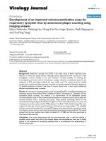
1.1
Industrial prototype of the Scooter cobot used at General Motors [6] . . . .
1
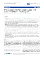
1.2
Scooter cobot at LIMS, Northwestern University . . . . . . . . . . . . . . .
2
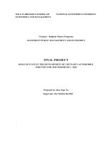
1.3
Collaborative Wheelchair Assistant at the National University of Singapore
4
2.1
Block diagram of a standard powered wheelchair. . . . . . . . . . . . . . . .
7
2.2
Block diagram of control of common prototypes of autonomous wheelchairs.
8
2.3
Block diagram of Collaborative Wheelchair Assistant. The user gives movement commands to the wheelchair through an access method. The signals
from the access method are passed to user interface. Information from User
Interface, Positioning Sensors Readings and Mode Detection dictated by the
user will help the navigation system to give the correct commands which will
be translated into motor commands that are passed to the motor controller.
13
2.4
Frames and Notations. . . . . . . . . . . . . . . . . . . . . . . . . . . . . . .
14
2.5
Schematic diagram of kinematics model of CWA. . . . . . . . . . . . . . . .
16
3.1
Input normal to the current cobot’s direction used as to deviate from the
prescribed path.
3.2
. . . . . . . . . . . . . . . . . . . . . . . . . . . . . . . . .
Projection of normal input (relative to a local cobot frame) on the normal
to the guiding path used to deviate from this guideway. . . . . . . . . . . .
3.3
21
21
Elastic Factor as a function of the elastic force and distance to the guiding
path. . . . . . . . . . . . . . . . . . . . . . . . . . . . . . . . . . . . . . . . .
22
3.4
Block diagram of Elastic path controller for Collaborative Wheelchair . . .
24
4.1
Scooter cobot . . . . . . . . . . . . . . . . . . . . . . . . . . . . . . . . . . .
27
4.2
Kinematics Model of Scooter cobot . . . . . . . . . . . . . . . . . . . . . . .
28
viii
4.3
Relationship among Elastic Factor in rotary, Torque and Distance . . . . .
30
4.4
Block diagram of Elastic path controller for Scooter cobot . . . . . . . . . .
32
5.1
Graphical User Interface for Cobot Simulator . . . . . . . . . . . . . . . . .
34
5.2
Joystick Frames and Settings Illustration . . . . . . . . . . . . . . . . . . . .
35
5.3
Simulation flowchart . . . . . . . . . . . . . . . . . . . . . . . . . . . . . . .
37
5.4
Wheelchair in guided mode. . . . . . . . . . . . . . . . . . . . . . . . . . . .
38
5.5
Guided mode performance with the wheelchair on a sinusoidal wave . . . .
39
5.6
Elastic mode to avoid an obstacle with the CWA (Filled circle on the path
is the obstacle). . . . . . . . . . . . . . . . . . . . . . . . . . . . . . . . . . .
39
5.7
Elastic mode performance on sine wave. . . . . . . . . . . . . . . . . . . . .
40
5.8
Effect of three different methods of computing the input to the elastic path
controller . . . . . . . . . . . . . . . . . . . . . . . . . . . . . . . . . . . . .
41
6.1
Environment to learn moving Scooter cobot . . . . . . . . . . . . . . . . . .
44
6.2
In first experiment, we test how users can avoid an obstacle placed along a
straight line using the elastic path controller. . . . . . . . . . . . . . . . . .
44
6.3
Frequency contents of Normal force and high-frequency area. . . . . . . . .
45
6.4
Learning to avoid obstacles using the elastic mode. This subject (Jeffrey)
first hit the obstacle(trajectories not going back to 0) and gradually learned
to avoid it successfully. . . . . . . . . . . . . . . . . . . . . . . . . . . . . . .
47
6.5
Normal force of Jeffrey’s trials. . . . . . . . . . . . . . . . . . . . . . . . . .
48
6.6
Scotty seems to learn avoiding the obstacle in less trials and more easily than
Jeffrey (compare with Figure 6.4) . . . . . . . . . . . . . . . . . . . . . . . .
49
6.7
Normal force of Scotty’s trials. . . . . . . . . . . . . . . . . . . . . . . . . .
50
6.8
High frequency content divided by total frequency content as a function of
the trial number for two typical subjects. . . . . . . . . . . . . . . . . . . .
6.9
51
Proportion of high frequency content of first five and last five trials for all
subjects. . . . . . . . . . . . . . . . . . . . . . . . . . . . . . . . . . . . . . .
52
6.10 Environment for the hidden path experiment . . . . . . . . . . . . . . . . .
53
6.11 Paths used in the 12 trials by two typical subjects. . . . . . . . . . . . . . .
54
ix
6.12 Determination of divergence time using the standard deviation of the y position (as a function of the time). (a) and (b) correspond to two typical
subjects. . . . . . . . . . . . . . . . . . . . . . . . . . . . . . . . . . . . . . .
55
6.13 Force profiles of two typical subjects with force dropping time depicted as ‘+’. 56
6.14 Points of dropping force ’+’ and mean of these points ( ) compared with the
divergence position represented by the dashed bar. Note that the dropping
points is generally slightly before the divergence point and about at the same
x-position than the obstacle. . . . . . . . . . . . . . . . . . . . . . . . . . . .
58
6.15 Mean and standard deviation of difference between x-position of the divergence point and dropping points of the 12 trajectories, for the 7 subjects. .
59
6.16 Differences between the divergence point and the mean x position corresponding to the dropping time in the four different directions. Each bar
corresponds to the difference between the mean x position of over three trials
in one direction and the divergence point, for a given subject. . . . . . . . .
60
6.17 Difference in x-position between the mean dropping point and obstacle, for
all subjects. . . . . . . . . . . . . . . . . . . . . . . . . . . . . . . . . . . . .
60
x
List of Tables
5.1
Table of functionality of joystick mapping . . . . . . . . . . . . . . . . . . .
36
6.1
Statistics of trials hitting the obstacle. . . . . . . . . . . . . . . . . . . . . .
46
1
Chapter 1
Introduction
COBOT (for Collaborative Robot) was invented by Edward Colgate and Michael Peshkin
from Northwestern University. “Cobots” are intended for direct interaction with a human
worker, handling a shared payload [3]. Cobot is a device activated by operator’s movement
such as pushing or pulling(Figure 1.1). It is passive, i.e. will not move without power
provided by the user, and is thus intrinsically safe.
Figure 1.1. Industrial prototype of the Scooter cobot used at General Motors [6]
Cobots interact with people by producing software-defined“virtual surfaces” which constrain
and guide the motion of the shared payload. Ergonomic as well as productivity benefits
2
result from combining the strength of the cobot with the sensing and dexterity of the
human worker [3]. Cobot can follow a pre-defined path stored in the outfitted computer
using a “Path following” control. Path following drives an object along a geometric path
without a timing law assigned to it. Path following is a useful motion control approach
when maneuvering mobile robots from one area to another[4]. Since cobot depends less on
the sensors or other localization devices from which the moving error usually comes, it is
supposed to complete the task with a higher efficiency and accuracy.
Figure 1.2. Scooter cobot at LIMS, Northwestern University
The Scooter cobot on which experiments have been performed for this thesis is a mobile
platform moving in the two-dimensional plane: (x, y, θ)(Figure 1.2). This prototype was
conceived to facilitate the placement/removing of car doors in the assembly line [5].
Cobots have two basic motion modes: free mode (FM) and guided mode (GM). In free
mode, the cobot behaves like a chair with casters. In guided mode it is constrained along a
virtual guideway which is defined in software. Eng Seng et al. could show in experiments
[14] that less effort is required to move in guided than in free motion. Further, movements
in GM are faster, smoother, and require less back and forth correction than in FM. Simple
3
and efficient methods to define ergonomic guiding paths were also developed in [10].
A problem arises with guided motion when an obstacle or a person is standing on the guiding
path, the obstacle had to be removed before the cobot can proceed on. A solution to this
problem may be to provide the operator means to avoid obstacles. In common mobile
robotics, obstacle avoidance is achieved by using sensors and heavy sensor processing to
detect the obstacles, and by modifying the path planning correspondingly. However, cobots
work with a human operator who is equipped with natural sensors and powerful sensor
processing, in particular vision. Our idea is thus to provide the operator an Elastic Path
Controller with which he or she can avoid obstacles, by pushing the cobot when he or she
detects the obstacle.
We envision that with this Elastic Path Controller (EPC) the cobot can follow the predefined guiding path when no obstacle is detected and the operator wants to keep moving.
The EPC enables the operator to deform the guiding path when the obstacle is detected,
and bring the cobot back to the guiding path when the obstacle is passed. Using it, the
user will be able to go through narrow passages, what may be difficult and even dangerous
with autonomous navigation systems if odometry is not sufficiently accurate. The user can
use his own judgement to perform necessary correction during movement.
A collaborative wheelchair is developed at NUS[9], which uses virtual guideways to
help disabled to maneuver their wheelchair according to their needs. Our Collaborative
Wheelchair Assistant (CWA) was built on a commercial wheelchair YAMAHA JW-1 (Figure
1.3). Previous attempts with robotic wheelchairs have shown that disabled are generally not
satisfied with fully autonomous wheelchairs. Despite heavy computation to recognize the
environment and perform motion planning, an automatic wheelchair frustrates the disabled
from their freedom to control the motion, to stop for observing something or to chat with
a friend.
This thesis develops such an Elastic Path Controller and tests it in simulations and in
4
Figure 1.3. Collaborative Wheelchair Assistant at the National University of Singapore
experiments performed on the Scooter cobot(Figure 1.2) and the Collaborative Wheelchair
Assistant. The CWA[9] has an unicycle-type kinematics. The Scooter is a triangular vehicle
moving on a plane, with a steerable wheel at each corner. However for simplicity a twosteering-type vehicle kinematics model was adopted to control two of three steering wheels
in our experiments, and the third wheel was controlled to go through the intersection formed
by axes of two steering wheels.
Simulations have been performed to develop and test the EPC. Unicycle and two-steeringwheels type kinematics corresponding to the CWA and Scooter were considered. The simulation environment consisted of a joystick connected to a computer with graphical user
interface controlled by a MATLAB program. Several controllers were tested for each kinematics model, including the feedback linearization based controller proposed by Samson
[15, 19, 17] and a nonlinear Lyapunov-oriented controller from Micaelli and Samson [16, 18]
in 1993. These controllers were adapted to realize the elastic characteristic.
Experiments have been performed on the Scooter to investigate the performance of the
elastic path controller, using the feedback linearization based version. One experiment
5
investigated whether and how the users can train the cobot to avoid obstacles using the
EPC, and examined its efficiency and accuracy. Another experiment investigated which
strategies the users use to work with the EPC. The results suggest that the EPC is easy to
learn and an efficient mean of modifying the desired path for collaborative robots.
The kinematics and the elastic path planners for the CWA and Scooter cobot are described
in chapters 2 and 4. Simulation of the elastic path controller are presented in Chapter 5.
Chapter 6 presents experiments performed on the Scooter Cobot to investigate performance
with the Elastic Path Planner. Conclusions and suggestions for further research are given
in Chapter 7.
6
Chapter 2
The Collaborative Wheelchair
Assistant
In this chapter, a review of past research projects about robotics wheelchair which have been
applied to assist people with disabilities has been introduced. Furthermore, the kinematics
model of our wheelchair platform and its path controller has been derived.
2.1
Research on Robotic Wheelchairs
A person’s control of his/her personal space is an important component of human
dignity and the quality of life [20].
Robotics technology has been applied to assist people with disabilities. Robotics wheelchair
is an important part in this broad field.
Figure 2.1 shows the block diagram of a standard powered wheelchair. The user interacts
with the wheelchair using an access method such as joystick or sip-and-puff system. The
commands given through the access method are passed to the wheelchair controller as motor
commands consisting of a direction component and a speed component.
Research in the field of robotic wheelchairs seeks to address issues such as safe navigation,
splitting control between the user and the wheelchair, and creating systems that will be usable by the target population. Robotic wheelchairs are usually built with standard powered
7
Figure 2.1. Block diagram of a standard powered wheelchair.
wheelchairs for their bases as the research focus is not on improving the mechanical design
of the standard powered wheelchair. [22] presents a literature review covering many aspects
of powered mobility and [23] discusses issues for engineering both powered and manual
wheelchairs.
Figure 2.2 shows the block diagram of common autonomous wheelchair systems. The user
gives commands to the user interface using an access method. The command from the user
interface is passed to the navigation system along with sensor readings and information
from the vision system. Sensor readings are also used for mode detection, which determines
the proper navigation code to use for the current environment. The navigation system
computes the correct motor commands and passes them to the motor control.
The OMNI project[24, 26, 27, 25] uses a custom-designed omnidirectional wheelchair as its
base. Some ultrasonic and infrared sensors provide assistance through obstacle avoidance,
wall following and door passage. The wheelchair can rotate around its center point, allowing
it to move in tighter spaces than a standard powered wheelchair base.
Another custom designed omnidirectional wheelchair was built in the Mechanical Engineering department at MIT[28]. Semi-autonomous control and autonomous control were assisted
by ultrasonic sensors. Horseback riding strategy was used in semi-autonomous control. A
8
Figure 2.2. Block diagram of control of common prototypes of autonomous wheelchairs.
9
horse will follow its rider’s commands, but not if they put the horse in danger.
A system built by Connell[29] also follows a horseback riding analogy. The user would sit
on a chair on a mobile robot base. A joystick was used for driving the system. A bank of
toggle switches were used to turn on or off the ability of the robot to perform some tasks
autonomously. These behaviors include obstacle avoidance, hallway traversal, turning at
doors and following other moving objects. The robot is equipped with ultrasonic, infrared
and bump sensors.
An autonomous robotic wheelchair was developed at Arizona State University[30]. The
purpose of the system was to transport its user to a specified room in a building using a map
of the environment. The wheelchair has been equipped with an on-board microcomputer,
a digital camera, and a scanning ultrasonic rangefinder for obstacle avoidance. The system
used only a restricted amount of vision processing to locate and verify known objects such
as room numbers, look at elevator lights and keep the wheelchair centered in the hallway.
Wheelesley[32] project is based on the platform built by KISS Institute for Practical Robotics.
Wheelesley consists of an electric wheelchair outfitted with a computer and infrared, bump
and ultrasonic sensors and a laptop that is used for the user interface. The user interface
developed allows the user to operate in three modes: manual, joystick and user interface. In
manual mode, the wheelchair functions as a normal electric wheelchair. In joystick mode,
the user issues directional command through the joystick while the robot will avoid objects
in the requested path. In user interface mode, the user interacts with the robot solely
through the user interface. The robot can travel semi-autonomously in an indoor environment. This allows the user to issue general directional commands and to rely upon the
robot to carry out the low level routines such as object avoidance and wall following.
Hephaestus, the greek god of fire, craftsmen and smiths was the only Olympian with a
disability. To compensate for his disability Hephaestus built two robots, one silver and
one gold, to transport him. The Hephaestus Smart Wheelchair System[34] aims to be a
10
navigation assistant that can be added to any powered wheelchair. The system would be
installed between the wheelchair’s joystick and motor controller. The first prototype has
been tried with one powered wheelchair base.
The NavChair navigates in indoor office environments using ultrasonic sensors, and an
interface module interposed between the joystick and power module of the wheelchair.
The NavChair has three operating modes: general obstacle avoidance, door passage, and
automatic wall following.
The system can select a mode automatically based on the
environment[36]. The NavChair has application to the development and testing of“shared
control” systems where a human and machine share control of a system and the machine
can automatically adapt to human behaviors.
Senario[38, 39]can be operated in a semi-autonomous or fully autonomous mode. In semiautonomous mode, the system accepts commands through a voice-activated or joystick
interface and supports robot motion with obstacle/collision avoidance features. Fully autonomous mode is a superset of semi-autonomous mode with the additional ability to
execute autonomously high-level go-to-goal commands. The user can override in semiautonomous mode. The wheelchair will stop moving if an emergency situation is detected.
The system uses 13 ultrasonic sensors, split into navigation sensors and protection sensors.
Two encoders provide a rough orientation estimate. Two infrared range finders mounted at
192cm (above the user’s head) are also used for calculating positioning information.
A deictic navigation system has been developed for shared control of a robotic wheelchair[40].
Shared control approach divides task responsibilities between the user(high level) and the
robot(low level). The user of the wheelchair tells the robot where to go by clicking on a
landmark in the screen image from the robot’s camera and by setting parameters for motion, where the target should be at the end of motion, what the distance between the robot
and the target at the end of the motion and the desired speed in a computer window. The
robot then extracts the region around the mouse click to determine to which landmark the
11
user wishes to travel. It then uses the parameters to plan and execute the route to the
landmark.
Wakaumi[41]developed a robotic wheelchair that drove along a magnetic ferrite marker lane.
A magnetic lane is preferable to other nonmagnetic materials due to its ability to continue
to work in the presence of dirt on the line. Two infrared sensors in front of the wheelchair
have been added for obstacle detection. This type of system is useful for a nursing home
environment to allow people to drive around without the need for being pushed by a care
giver.
A wheelchair developed at Notre Dame[42] provides task-level supervisory control; the user
can select the nominal speed, stop and select a new destination or stop and take over
control. The system is taught ’reference paths’ during set up which are stored in memory.
Visual assistance from two cameras are used to correct errors. The system does not include
obstacle avoidance function. If an obstacle is put on the path, the operator needs to take
over control to maneuver around it and can then pass control back to the system.
The VAHM project[43, 44] operates in an assisted manual mode and an automatic mode.
The philosophy of this project is the person supervises the robot in automatic mode, overriding robotic commands that are unwanted, and the robot supervisees the person in assisted
manual mode, overriding commands that put the user in danger.
The Intelligent Wheelchair Project[45] is developed at University of Texas. The wheelchair
is enabled with active vision and other sensing modes, spatial knowledge representation and
reasoning. The environment is learned through local observations. The system uses stereo
color vision, in addition to ultrasonic and infrared sensors to assist movement.
A pushrim-activated power-assisted wheelchair (PAPAW) that use a combination of human
power and electric power has been developed[46, 47]. The human power is delivered by the
arms through the pushrims while the electric power is delivered by a battery through two
12
electric motors. The peak torque used to push the rim was significantly reduced. Intuitive
control reduces the strain on the upper extremities commonly associated with secondary
disabling conditions among manual wheelchair users.
2.2
Definition of the Collaborative Wheelchair Assistant
The Collaborative Wheelchair Assistant (CWA) implements path constraints to facilitate
manoeuvering of a wheelchair. The current prototype is based on a commercial wheelchair
with a laptop providing control and a graphical user interface. This platform enables development of human-machine interface strategies[9], in particular the elastic path controller,
which will enable operators to deform the desired path and so avoid obstacles and modify
the path when necessary. These path modifications are controlled by the user via some
interface, currently a joystick, so rely on the capabilities of the user and do not require external sensors or sensor processing. Figure 2.3 is the block diagram of this new application
of cobot.
While the members of the target community may have different disabilities, we assume
that they have some common abilities. We expect that any potential user can see and give
high-level commands to the wheelchair through some access method. We also assume that
potential users have the cognitive ability to learn to operate the system. Finally we require
that the system be able to navigate in indoor and outdoor environments.
2.3
2.3.1
Kinematics
Kinematics model of a moving point
Following the exposition of [18], we will first look at the kinematics model of a moving
point, corresponding to Figure 2.4.
13
Figure 2.3. Block diagram of Collaborative Wheelchair Assistant. The user gives movement commands
to the wheelchair through an access method. The signals from the access method are passed to user
interface. Information from User Interface, Positioning Sensors Readings and Mode Detection dictated
by the user will help the navigation system to give the correct commands which will be translated into
motor commands that are passed to the motor controller.
14
Definition 2.3.1. M is a point which is moving to the curve C defined in the Frenet frame
T . The point P is the orthogonal projection of the point M onto the curve C. And O is
the origin of the global frame R.
Figure 2.4. Frames and Notations.
A classical law of Mechanics gives:
−−→
dOM
dt
−−→
dOP
dt
=
R
+
R
−−→
dP M
dt
−−→
+ wc × P M
(2.3.1)
T
With
−−→
PM
T
= y
0
−→
Wc =
0
0
0
θ˙c = cc (s)s˙
(2.3.2)
and
s, y: Curvilinear coordinate of a point (M) along the guiding path and its normal distance
θc : The angle of the tangent to the guiding path relative to the fixed frame (x,y)
15
cc (s): The changing curvature of the guiding path
−−→
dOM
dt
−−→
dOP
dt
: The velocity of point M measured on the reference frame(R)
R
: The velocity of point T to the frame(R)
R
−−→
dP M
dt
−−→
+ wc × P M : The velocity of point M to the frame(T )
T
[wc ]R : the rotation velocity vector of frame(T ) w.r.t frame (R)
d
dt
: time derivation w.r.t the frame(R), cc (s) is the path’s curvature at frame(T ).
R
Then the system equations of a point relative to a given curve are (For details, please refer
to Appendix A):
X˙
s˙ = (cos θc sin θc ) · ˙ /[1 − cc (s)y]
Y
X˙
y˙ = (− sin θc cos θc ) ·
Y˙
(2.3.3)
and
˙ Y˙ : The velocities of the point along the abscissa and ordinate of the fixed frame (x, y).
X,
This set of equations can also be regarded as the transformation relationship from frame(R)
to frame(T ) of a point.